A new all-solid-state lithium-ion battery working without a
separator in an electrolyte
Seonggyu Choa,b , Shinho Kima, Wonho Kimb, Seok Kimb Sungsook Ahna*
a Secondary Battery R&D Center, DRB Holdings Co.,
Pusan, 46329, South Korea
b Department of Chemical and Biochemical Engineering, Pusan National University,
Pusan, 46241, South Korea
Corresponding
*E-mail: [email protected]
Keywords: Secondary lithium ion battery; All-solid-state battery; Solid polymer electrolyte; Succinonitrile (SN); lithium(trifluoromethanesulfonyl)imide (LiTFSI)
ABSTRACT
Considering the safety issues of Li ion batteries, all-solid-state polymer electrolyte has been one of the promising solutions. In this point, achieving a Li ion conductivity in the solid state electrolytes comparable to liquid electrolytes (>1 mS/cm) is particularly challenging. Employment of polyethylene oxide (PEO) solid electrolyte has not been not enough in this point due to high crystallinity. In this study, hybrid solid electrolyte (HSE) systems are designed with Li1.3Al0.3Ti0.7(PO4)3(LATP), PEO and Lithium hexafluorophosphate (LiPF6) or
Lithium bis(trifluoromethanesulfonyl)imide (LiTFSI). Hybrid solid cathode (HSC) is also designed using LATP, PEO and lithium cobalt oxide (LiCoO2, LCO) − lithium manganese
oxide (LiMn2O4, LMO). The designed HSE system displays 3.0×10⁻⁴ S/cm (55 ℃) and
1.8×10⁻³ S/cm (23 ℃) with an electrochemical stability as of 6.0V without any separation
Introduction
Li ion batteries have been credited for a great revolution of the strong intermittent renewable-energy sources replacing fossil fuels. They also critically contribute to the development of communication and transportation by the rise of super-slim smart phones and electric cars in a practical range. However, since announced in 1991, heels of Li ion battery phones and laptops have been recalled because of a flame causing injury to the users1. The
cycle life is very limited because of poor cycling efficiency of Li electrode. The secondary cells are more sensitive to impurities such as water in the electrolyte and the electrode materials. And the cells under running would have Li dendrites leading to occasional explosions. Nonetheless, because of radical needs for high energy density and reliability of batteries, Li technology has been ceaselessly focused on. With high energy density and large capacity suitable for energy storage systems, Li ion is almost unique with low atomic weight compared to all other negative electrode materials that had been ever investigated.
The typical Li ion batteries consist of a negative anode, a positive cathode and a liquid electrolyte. However, many energy storage devices based on combustible organic solvents inevitably carry the risks of leakage, heavier packaging and related hazards. A liquid electrolyte is volatile at high temperature when the battery is charged or discharged quickly or when packs of car batteries are damaged in accidents. Against inherent disadvantages of
liquid electrolytes2−3, solid electrolytes of nonflammable polymers4−5 and all-solid-state
battery using inorganic materials6-7 have been developed. When a battery releases power,
In many ways, all-solid-state constructions certainly enhance the overall performance of
energy storage and conversion8−10.
A potential solution against the disadvantage of solid-state electrolytes has been pursued11−15.
In this point, the conductivity of polymer electrolytes such as polyethylene oxide (PEO) is explained in terms of the electron donating activity, weak coordinate bond and hopping of Li ions16−17. As a solid polymer electrolyte, alkali crystalline complexes of PEO with metals
have been investigatedbecause of significant ion conductivity18−22. However, Li agent in PEO
has not been enough to generate effective ionic conductivity because high crystallinity of PEO bothers the Li ion movement5. Amorphous sites of PEO contribute to enhance the Li ion
movement especially at room temperature22−26. When the PEO complex with relatively low
glass transition temperature (Tg) becomes amorphous the ion conductivity exhibit 10-5~10-4
cm-1 corresponding to 3~4 times higher than those of crystallites. However, when PEO
complex displays liquid-like property which simultaneously induces short-circuits.
Oxide solid electrolytes. Inorganic oxides have been designed for electrolyte components27−30,
such as Perovskite-structured Li3xLa2/3-xTiO327, Garnet-structured Li7La3Zr2O12 (LLZO)28−29,
NASICON-structured Li1+xAlxTi2-x (LATP)30. Low conductivity (10-4~10-3 S/cm), high grain
boundary resistance and high calcination temperature of these oxide solid electrolytes cause increased volatility, phase transition and impurity, decreasing the total quality of Li ion battery. On the other hand, sulfide-based solid electrolyte including Li10GeP2S12 (LGPS)
display high conductivity almost similar to that of liquid electrolytes31. However, it is smelly,
expensive, unstable under air and reactive with water generating harmful H2S. A battery
system composed of lithium aluminum germanium phosphate (LAGP, Li1.5Al0.5Ge1.5(PO4)3,)
and PEO has been tried with protecting layers32. The drawback of this system is a specific
interaction of LAGP with Li metal and working at 50 °C but not at room temperature. One of the oxide solid electrolytes, lithium aluminum titanium phosphate (LATP) is highly stable under air and inexpensive. But LATP exhibits lower ion conductivity than that of liquid electrolyte or sulfide-based electrolytes, reduction of Ti4+ into Ti3+ by the interaction of Li ion,
and high grain boundary resistance33. To overcome these problems, protecting layer of thin
layers composed of PEO34 or Al2O335 has been introduced to minimize the interaction with Li
exhibits 5.03×10⁻⁶ S/cm at 23 °C36. In this study, battery systems are designed without
protecting layers, which effectively work at room temperature.
Succinonitrile (SN) Introduction. The lithium bis(trifluoromethanesulfonyl)imide (LiTFSI) exhibits limitation in narrow electrochemical windows (~4.8V) and low electrochemical stability37−38. To overcome these disadvantages, nonionic polymeric crystalline with excellent
electrochemical stability is obtained by using succinonitrile (SN). Nitrile compounds are typically safe against fire and chemically stable at harsh conditions. SN has Tg of −40 ℃ and
melting temperature (Tm) of 55 ℃. Between these temperatures SN suppresses the
crystallization of PEO and increases the physical stability against short-circuit. In addition, SN is highly polar to enhance the Li salt dissolution and movement. When SN forms a complex with LiTFSI, the conductivity increases up to 1×10⁻³ S/cm (25 ℃) due to molecular
rotation and trans-gauche isomerism39−40. Even though LGPS is relatively expensive and
reactive with water generating unfavorable H2S41, LGPS+PEO+SN hybrid system does not
bother Li ion movement thus conductivity due to SN contribution42. Using relatively
inexpensive LAGP, LAGP+PEO and LAGP+PEO+SN hybrid systems have been developed43.
The chemical reactivity of Li ions with solid electrolyte determines the ionic conductivity but this has not been fully investigated for LAGP+PEO+SN hybrid systems. In addition, the lattice structure of solid electrolytes modified by Ti ion reduction affects the Li ion movement.
The complex composed of Ti4+ typically generates the conductivity close to 10−3 S/cm while
that of Ti3+ significantly decreases the conductivity to 10−7 S/cm. The LAGP, PEO and SN
system without protecting layer has been tried35,43 but there is a lack of systematic
electrochemical analysis to verify the interaction with Li ion.
scanning voltammetry (LSV) curves of the designed electrodes confirm the extended region of electrochemical windows of PEO-only system which is originally narrow near 4.8V.
Results
Design of hybrid solid electrolytes (HSE) and hybrid solid cathode (HSC). This study introduces designed hybrid solid electrolyte (HSE) and hybrid solid cathode (HSC). The designed HSCs are combined with lithium ion manganese oxide (LMO, LiMn2O4 or Li2MnO3) and
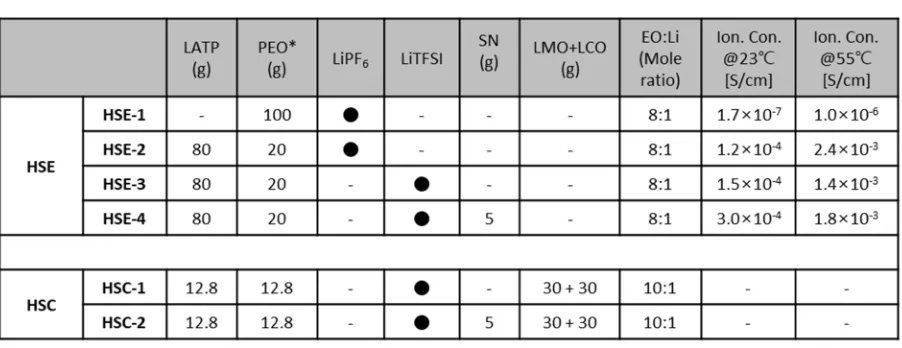
lithium cobalt oxide (LCO, LiCoO2). In Table 1, composition and ion conductivity of the
designed HSC and HSE are summarized at two temperature conditions (23 and 55 °C).
Li ion-conducting polyethylene oxide (PEO) is mixed with lithium aluminum titanium phosphates (LATP) synthesized in this study (Experimental Section). This sticky white HSE slurry is casted on Al or Li metal foil. For better casting process, the viscosity of the slurry is modified by controlling the content of LATP and PEO as well as molecular weight of PEO. The battery efficiency is compared with lithium(trifluoromethanesulfonyl)imide (LiTFSI) and lithium hexafluorophosphate (LiPF6). In addition, the function of succinonitrile (SN) is
evaluated in terms of the interaction with PEO and LiTFSI. Ion conductivity is compared with pure PEO electrolyte (HSE-1) and PEO/LATP (20/80) composite electrolyte with LiPF6
(HSE-2). With LiTFSI, PEO/LATP (20/80) composite electrolyte without (HSE-3) and with (HSE-4) SN incorporation are compared. Two types of LMO/LCO (30/30) based cathodes are compared containing PEO/LATP (12.8/12.8) composite combined with LiTFSI, without (HSC-1) and with (HSC-2) SN incorporation
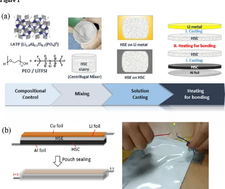
A representative coin cell preparation using the designed HSE-4 and HSC-2 is illustrated in Fig. 1a. The slurry is coated on anodic Li metal foil by solution casting. LATP, PEO, LiTFSI and SN are mixed in a designed composition using a centrifugal mixer (Thinky Mixer) resulting in a sticky white HSE-4 slurry. LMO and LCO are mixed with PEO and SN, resulting in HSC-2. The HSC-2 is coated on Al foil, followed by HSE-4 slurry casting. The Li metal anode and the designed cathode plates are bonded by heating HSE sides to form a layered structure of a coin cell. In addition, this process is scaled-up for a pouch cell (5 ×10 cm2) in which copper foil is additionally employed outside of the Li metal plate for physical
even at the broken situation without any leakage and short-circuits (Supporting Information, Movie S1).
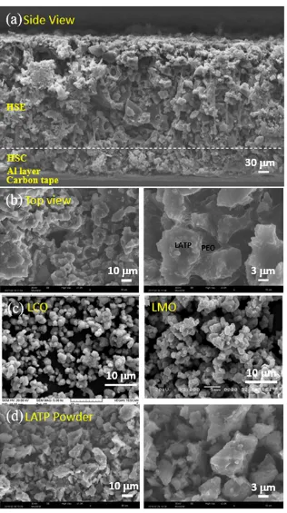
Structure of the all-solid-state battery system. The simplified battery sample is prepared to investigate the performance of HSE and HSC, which are casted and dried on a carbon tape in a layered structure stacked from Al foil, cathodic (HSC-2) and electrolyte (HSE-4) layers without anodic Li metal and protective Cu foil layers. A representative scanning electron microscopy (SEM) image of each layer is shown in a cross-sectional side-view (Fig 2a) and in a top-view (Fig 2b). In the cross-sectional image, the size of particulates in HSC layer (below the dotted-line in the picture) is smaller compared with those in the HSE layer, this is caused from relatively small size of the LCO and LMO particles (Fig 2c). The images of pure LATP powder at the same resolutions are compared in Fig 2d. The top-view images of the designed battery system (Fig 2b) are similar to those of the LATP powder pellet (Fig 2d). For all the systems, the inter-particulate spaces are effectively filled with PEO binding. The SEM images confirm effective physical contact of ion-conducting PEO and solid LATP in the designed HSE layer without phase separation, which is crucial for high ionic conductivity of a battery. Fig. 2b depicts the reticulated PEO connects LATP particles forming ion-conducting pathways, which can decrease boundary resistance in the solid LATP electrolyte. All of these morphologies are advantageous for the increase in the bulk ionic conductivity44.
Conductivity of the designed systems. The total resistance is evaluated by ionic conductivity based on the electrochemical impedance spectroscopy (EIS) (Table 1). Using the measured resistance and following relation, ionic conductivity (σ, S/cm) of the designed HSE and HSC is evaluated,
𝜎 =
∙ (1)where, l is the thickness (cm) of the HSE, A is the area (cm2) of the sample, S is the total
resistance (Ω) obtained from EIS spectra. The ionic conductivity of the designed HSE shows almost three orders higher (~10−4 S/cm) than that of pure PEO (10−6~10−8 S/cm)45 at the same
EO to Li (8:1). This result confirms the contribution of high ionic conductivity of LATP embedded in the ion-conducting PEO by the reduced bulk and boundary resistance. Due to characteristic temperature-dependence46, ionic conductivity at 55 ℃ is about 10 times higher
@ 23 °C & 1.8 × 10⁻³ S/cm @ 55 °C) are enhanced compared with those (1.5 × 10⁻⁴ S/cm
@ 23 °C & 1.4 × 10⁻³ S/cm @ 55 °C) without SN introduction by increased segmental
mobility of PEO in HSE47−48. Especially the increase of ionic conductivity by SN
introduction is prominent at room temperature than that at 55 °C.
Solid electrolyte interface (SEI). Even with several controversies49−50 the LATP and Li
metal is reported to react immediately upon a physical contact and forms unfavorable solid electrolyte interface (SEI) layer on the Li metal surface. This unfavorable phenomenon bothers the Li ion movement thus decreases the ionic conductivity. However, this is suppressed by surface modification using stealthy PEO coating51. The role of PEO in HSE is,
at the same context, surrounding each LATP particle to protect the Li metal surface. The efficacy of the designed HSE on Li metal anode is investigated by measuring the AC impedance as a function of time (Fig 3). Impedance (Z) is composed of reactance and resistance by the relation,
Z = R + jX (2)
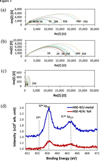
where, the real part R is the resistance, while imaginary part X is the reactance. The chemical reaction of the designed model cells symmetrically composed of Li/LATP/Li and Li/HSE/Li are evaluated for 25 days. Among them, selected results of Li/LATP/Li (Fig 3a), Li/HSE-1/Li (Fig 3b) and Li/HSE-4/Li (Fig 3c) are shown. The increase in the resistance and reactance has been observed in the system of LATP/Li metal51 and PEO/Li metal by the characteristic
chemical reactions37. The interfacial resistance of the symmetric cells designed as
Li/LATP/Li (Fig 3a) and Li/HSE-1/Li (Fig 3b) continuously increase the resistance and reactance for 25 days. However, the resistance of the Li/HSE-4/Li cell maintains almost similar low value for total 25 days (Fig 3c). The result suggests that the reaction of HSE-4 on Li metal is far more effective than that of LATP.
In order to evaluate the impedance result aforementioned, X-ray photoelectron spectroscopy (XPS) measurements of the HSE samples are performed before and after the reaction with Li metals (Fig. 3d). For this, Ti peaks of HSE-4 pasted on Li metal after the dynamic charging-discharging procedures (blue line) are compared with HSE-4 on Al foil, the physical substrate (red line) employed as a standard. Exposed to air, Ti is mostly present as TiO2 (Ti appears as
Doublet peaks consist of Ti 2p1/2 and Ti 2p3/2: two strong Ti4+ peaks, i.e., 2p1/2 (Ti4+, 464.6 eV)
and 2p3/2 oxide (Ti4+, 458.8 eV), two Ti3+ peaks (457 eV and 463.1 eV) and two Ti2+ peaks
(455.3 eV and 461.7 eV), as well as two metallic Ti peaks (454.3 eV and 460.5 eV). Even with physical contact of LATP with Li metal, the binding energy of two samples in this study is same. The resulting XPS has no difference where the Ti 2p1/2 and Ti 2p3/2 remains at the
same energy position, indicating there is no Ti reduction (from Ti4+ to Ti3+)51. Therefore, there
is no lattice structure change induced by Ti rearrangement which otherwise affects the Li ion movement thus electrical conductivity eventually.
The mean thickness (d) of an organic coating on Ti nanocrystals, formed by the chemical grafting in HSE, is related with the intensity (I) of the Ti 2p3/2 signal originating from the
substrate in XPS measurements,53
I ∝ I0 σρ e–(d/λsinΘ) (3)
where, σ is the cross section, ρ is the density of the element, λ is the inelastic mean free path and Θ is the angle between the sample and the detector. The σ is specific for each orbital and depends on the photon energy (decreasing with increased photon energy). The λ is a measure of how far an electron can travel in a solid before losing energy54, this is dependent on the
photon energy. If normal emission and a flat surface is assumed the angle contribution of the intensity can be neglected. The XPS result shows the evolution of Ti 2p peak with decreased actual film depth after interaction with Li for 25 days. Both Ti 2p3/2 and Ti 2p1/2 intensities are
increased for Ti films on Li metal in comparison to that of the intact HSE on Al foil. This type of signal augmentation might be ascribed to the partial blocking effect of intact HSE on the escape of photoelectrons from Ti to vacuum. Therefore, the designed battery is suggested to have advantages in terms of SEI formation after the charge-discharge procedure.
decomposed. For the sweeping down from that stage, the reductive stability was measured in a separate experiment. The liquid electrolyte used as a standard contrast is oxidized at 4.8V noticed by the sudden increase in current (blue line). HSE (HSE-3) and HSE+SN (HSE-4) are also oxidized even if the absolute current intensity is relatively lower than that of liquid electrolyte. This electrochemical investigation of the designed cells indicates protective film formation on the cathode surface at the first cycle which works as a solid electrolyte interphase (SEI) in liquid electrolytes. On the other hand, during the reduction procedure of both HSE-3 and HSE-4, the current is very low without noticeable peak in all voltage regions in this study. Since reduction generates no specific current peak, the HSE which includes LATP, PEO, LiTFSI and SN is electrochemically stable from 2.5 V to 6 V.
Property of the designed electrolytes. Due to inherent high boundary resistance, LATP
hardly generates high ionic conductivity. A value of ca. 3.4 × 10⁻³ S/cm at 293 K, is among
the highest conductivities reported for LATP-based systems.55−56 To overcome this
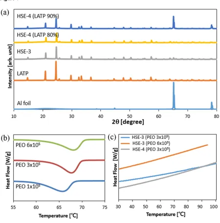
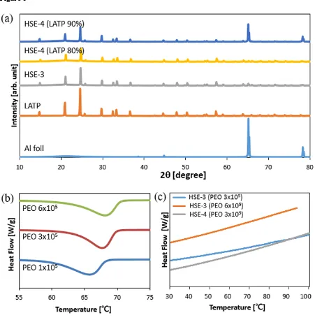
disadvantage, PEO is employed in this study. The structure of the PEO-incorporated system prepared on Al foil is investigated using X-ray powder diffraction (XRD) in Fig 5a. The XRD patterns of LATP-incorporated systems are almost similar34. XRD patterns of HSE
films exhibit lower intensity by the polymer incorporation without peak broadening. With the SN incorporation, XRD peak intensity becomes far lower, indicating the dilution of the whole system. Nonetheless the lattice structure is effectively maintained.
The ionic conductivity and thermal characteristics are modified according to the molecular weight of the PEO, which changes from 1×10⁵, 3×10⁵ to 6×10⁵ in this study. The segmental
mobility of PEO is investigated using differential scanning calorimetry (DSC) (Fig 5b). With the increase of PEO molecular weight, the peak temperature increases from 65.741°C (PEO Mw =1×10⁵), 67.663 °C (PEO Mw =3×10⁵) and 68.157 °C (PEO Mw =6×10⁵). Meanwhile, the
magnitude of the heat density decreases from 178.31 J/g, 172.41 J/g to 170.87 J/g. However, the designed HSE systems with LATP and SN do not generate characteristic peak at the given condition in Fig. 5c. This indicates that incorporation of LATP and SN effectively broadens the amorphous state to the wide temperature ranges, increasing the ionic conductivity at that condition. The DSC result of the system consisting of LiTFSI has been verified to become amorphous phase when the ratio of the [EO]/[Li] is higher than ten57. In this study the system
SN introduction. Based on this ionic conductivity result, the system with higher molecular
weight PEO Mw =6×10⁵ is selected to get enhanced mechanical property for the design of
HSE, while lower molecular weight PEO Mw =3×10⁵ is employed for better mixing efficacy
to design cathode electrode.
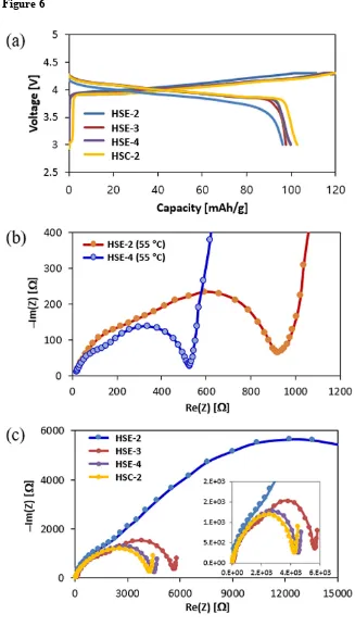
Capacity and 1st Coulomb efficiency of the designed coin cells. The Fig 6a shows specific
capacity-voltage curves of the first charge-discharge cycles of the selected model cell systems. The 1st cyclic profiles of LCO-LMO/HSE/Li metal system for each designed HSE-2, HSE-3
and HSE-4 and HSC-2/HSE-2/Li metal are compared at 55 ℃. The HSE-2 curve has more polarization loss compared to other curves. Further, the plateau region is quite broader for other three cases compared to the discharge curve of HSE-2 in terms of the slope nature. Although the difference is small in all the systems, the result of HSE-2 shows slight disadvantage compared to other three systems. Electrochemical Impedance Spectroscopy (EIS) results at 55 ℃ (Fig. 6b) and room temperature (Fig. 6c) are shown. LiPF6 is generally
used for liquid electrolytes, while LiClO4 and LiTFSI are favorably employed for solid
electrolyte systems. The ionic conductivity of the designed HSE is not so different (Table 1) but the resistance and charge-discharge efficacy in the designed Li ion cell are far different. LiPF6 (HSE-2) and LiTFSI (HSE-3, HSE-4& HSC-2) are used with PEO in this study, by
which physical properties of HSE-2 are far different from other three systems.
However, for both LiPF6 (HSE-1 & HSE-2 for this study) and LiTFSI incorporated systems
(HSE-3 & HSE-4 and HSC-1 & HSC-2 for this study), the resistance of the system in actual Li ion cell state becomes twice at 55 ℃ and four-times of that at room temperature. In Li ion cell state, the re-crystallization kinetics of PEO has been effectively slowed by the use of Li salts and bulky anions58. The moisture generated by the electrode cooling, decomposes LiPF
6
into PF5, leading to the resistance increase by the interaction between PEO and SEI59. By this
indicates that the moisture formation after the cooling procedure turns the LiPF6 into PF6 gas
and SEI in PEO, where SEI decreases the efficiency of the battery function significantly.
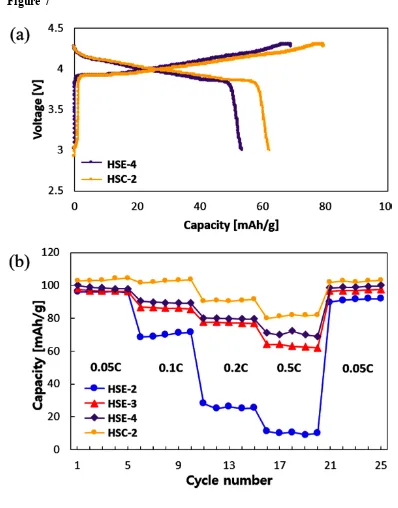
Fig. 7a displays 1st charge-discharge profiles of the LCO-LMO/electrolyte/Li metal systems
of selected HSE-4 and HSC-2 (both are based on LiTFSI+SN composition) at room temperature. This indicates that SN addition boosts the battery function compared with the cells employing LiPF6 (HSE-2) and LiTFSI-only (HSE-3) are not working effectively at
room temperature regardless of PEO molecular weight. The cells without SN (HSE-3) in electrolyte display 72 mAh/g at charging while 52 mAh/g at discharging as observed in Fig 6. On the other hand, SN incorporation (HSE-4) improves the property as of 78 mAh/g at charging while 59.7mAh/g at discharging. The difference is clearer by the C-rate performance (Fig. 7b). The C-rate values of each region are on the graph: 0.05 C, 0.1 C, 0.2 C, 0.5 C, and 0.05 C. At the 1st charging procedure, the capacity of each cell is 111.4 mAh/g (HSE-2), 118.5
mAh/g (HSE-3), 118.9 mAh/g (HSE-4), and 123.4 mAh/g (HSC-2), while at the discharging procedure, 96.2 mAh/g, 97.6 mAh/g, 99.9 mAh/g, and 102.7 mAh/g, respectively. Their Coulombic efficiency (also Faraday Efficiency) is 86.4%, 82.3%, 84.0%, and 83.2%, respectively by the ratio of discharged capacity to charged capacity.
Discussion
In this study, to select proper Li ion source for the designed HSE, LiPF6 and LiTFSI have
been employed and measured the internal resistance on actual charging-recharging repetition. The solid electrolyte LATP shows ion conductivity as of 3×10⁻³ S/cm at the state of Ti4+ but it
becomes far lower at the state of Ti3+ due to structural deformation, bothering Li ion
movement. The solid electrolyte interaction with Li ion promotes the reduction of Ti4+ into
Ti3+. In this point, LATP is not a good choice to be used with Li at the state of lower than
1.8V60. In this study, hybrid solid electrolyte (HSE) composed of LATP, PEO and SN is
designed without protection layer. We observed that there is no reduction of Ti4+ into Ti3
which is investigated by Electrochemical Impedance Spectroscopy (EIS). In this point, we suggest a new electrolyte system advantageously utilized in secondary Li ion battery. Even without any protecting layer the designed system shows no reduction of Ti. This is confirmed by XPS and high Li ion conductivity as of 2.6×10⁻⁴ S/cm at room temperature. The
In addition to new hybrid solid electrolyte (HSE), new hybrid solid cathode (HSC) systems are designed and investigated, composed of LATP, PEO, LiTFSi (or LiPF6) and SN. Typically
employed for mass-production, slurry casting methods are utilized followed by lamination to reduce contact resistance. According to the type of Li salts (LiTFSi or LiPF6), the designed
HSE and HSC exhibit differentiated ion conductivity at two temperatures (25 and 55°C). In addition, during the dynamic charge-discharge procedure of the designed Li ion cells, the effect of internal resistance on the charge-discharge procedure and C-rate changes are investigated. In terms of the ion conductivity, the HSE with LiPF6 and LiTFSI exhibit 1.2 and
1.5 × 10⁻⁴ S/cm, respectively. However, when these HSE is incorporated into the dynamic cell
function, the internal resistance decreases four-times. This leads to a greatly improved capacity by the difference of 1st charge-discharge and over-charge of each cell, which is more
prominent at room temperature than at 55 °C.
Conclusion
The moisture induced by the cooling procedure inevitably decomposes LiPF6 into PF5 gas
and SEI which reacts with PEO. With this phenomenon internal resistance increases thus LiTFSI is preferred over LiPF6 for PEO-based Li ion battery cell. In this study the
advantageous usefulness of LiTFSI is verified in this respect. The interaction of LATP with Li ions is investigated with the designed HSEs. XRD results after the charge-discharge procedure confirms that there is no Ti reduction (Ti4+ Ti3+) which can modify the lattice
structure thus the ion conductivity. LATP and Li ions are not reacted for 25 days without any increase in resistance. LATP has been reported to actively reactive with Li ions. This study sheds new light on the usefulness of LATP. With the help of the SN, the amorphous state of PEO becomes more stable contributing to increased ion conductivity.
Experimental Section
Chemicals. All chemicals were purchased and used without further purification: Conductive carbon black (Super-P, Timcal ,Canada), Li2O3 (Lithium carbonate, 99%, Sigma-Aldrich, USA), Al2O3
(Aluminum oxide, 99.99%, Sigma-Aldrich, USA),TiO2 (Cotiox KA-100, 98%, Cosmo Chemical,
South Korea),NH4H2PO4 (Ammonium dihydrogenphosphate, 99.999%,Sigma-Aldrich, USA), PEO
(Poly(ethylene oxide, MW =1×10⁵, 3×10⁵ and 6×10⁵, Sigma-Aldrich, USA),LiTFSI
(Bis(trifluoromethane) Sulfonimide lithium salt, 99.95%, Sigma-Aldrich, USA), LiPF6 (Lithium
hexafluorophosphate, 99.99%, Aldrich, USA), AN (Acetonitrile Anhydrous, 99.8%, Sigma-Aldrich, USA), SN (Succinonitrile, 99%, Sigma-Aldrich USA), LCO (PoscoESM, South Korea), LMO (G05, ILJIN materials, South Korea).
Synthesis of LATP. The solid electrolyte LATP (Li1.3Al0.3Ti0.7(PO4)3) was synthesized by a
conventional solid-state method. Stoichiometric amount of Li2CO3, Al2O3, TiO2, and
(NH4)H2PO4 were mixed in a ball mill for 12 hr. The slurry was sintered in a furnace at 900 ℃
for 2 hr. The dried powder was then jet milled at 1800 rpm for 2 hr to reduce the particle size. D-values (D10, D50 & D90) are measured for particle size evaluation as an intercept for 10%,
50% and 90% of the cumulative mass and D50 ~ 6 μm is obtained for effective mixing process.
Preparation of hybrid solid electrolytes (HSE) and hybrid solid electrolyte cathode (HSC). Li ion conducting polymer PEO is mixed with LiTFSI ([EO]:[Li]=8:1) and previously synthesized LATP (LATP:PEO=8:2 by weight) in acetonitrile (AN). The polymer solution is mixed using centrifugal mixer (THINKY mixer ARM-310) by 2000 rpm for 15 min. Then, with or without 5 wt. % of SN (Succinonitrile). The slurry is mixed again for 15 min. For the tests, this HSE slurry is casted on Al foil for analysis or on an electrode for coin cell test. After natural drying at room temperature for 1 hr, they are dried completely at 50 ℃ vacuum oven for 12 hr.
For better binding in the electrode, higher molecular weight of PEO (Mw~ 3×10⁵ and 6×10⁵)
were employed. LATP, PEO (LATP:PEO=5:5 by weight) and LiTFSI ([EO]:[Li]=10:1) were mixed in AN using THINKY mixer for 15 min. LiMn2O4 and LiCoO2 as active materials and
side, Li metal/HSE composite was dried at room temperature for 24 hr to avoid crumble. To evaluate the electrochemical performance, the CR2032 coin-type cell was fabricated with HSC/HSE composite and Li metal/HSE by laminate process. The construction of the cell is described as Fig. 1. All process was conducted in dry-room.
Characterization. Synthesized LATP and the HSC/HSE composites were observed using scanning electron microscope (SEM, SEC MiniSEM SNE-3000M) and X-ray diffraction (XRD, Rigaku MiniFlex600). XRD patterns of samples were obtained over a 2θ range from 10 deg to 80 deg with Cu Kα radiation at room temperature. The scan rate was 6 deg/min. Linear sweep voltammetry (LSV) was performed for both oxidation and reduction procedure for selected samples using potentiostat (Bio Logic SP-150) with scan rate of 20 mV/s from OCV to 1.5 V or 6.0 V. Ionic conductivity is calculated by AC impedance method with symmetric SS/Al/HSE/Al/SS cell using multi-channel potentiostat (Bio Logic VMP3). The samples were placed at 25 ℃ and 55 ℃ for 10 min, then analyzed from 500 kHz to 1 Hz at open-circuit voltage with 5.0 mV amplitude. With differential scanning calorimeter (DSC, DISCOVERY DSC2500), the calorimetric measurement is performed from room temperature to 100 ℃ at the heating rate of 10℃/min. The cell is cycled from 3 V to 4.3 V with 0.05 C for formation or each C-rate (1C = 1.5 mAcm-1) at room temperature or 55℃.
Acknowledgments
This research was supported by the Industrial Fundamental Technology Development Program (10052745, Development of the nano-sized (100 nm) manganese ceramic material for high voltage pseudo-capacitor) funded by the Ministry of Trade, Industry and Energy (MOTIE) of Korea.
Author Contributions
Additional Information
Supplementary information accompanies this paper https://www.nature.com. Competing Interests: The authors declare no competing interests.
Captions
Table 1. Composition of the designed hybrid solid electrolyte (HSE) and hybrid solid cathode (HSC) in this study. The ionic conductivities of HSE at 25 and 55 ℃ are shown. *PEO MW
=6×10⁵ g·mol-1, is used for HSE 1 to HSE 3, while PEO MW = 3 ×10⁵ g·mol-1 for HSC-1 and
HSC-2. For the whole battery design, HSE-1 to HSE-3 are combined with HSC-1, but HSC-2 is only combined with HSE-4.
Figure 1. (a) Preparation of all-solid-state coin-cell using the designed HSE and HSC in this study. (b) Configuration of all-solid-state pouch cell in 5×10 cm2 scale (left scheme) and its
operation (right picture)
Figure 2. SEM images of (a) cross-section and (b) Top view of HSE-3/CHSE-1/Al foil on carbon tape (c) LCO and LMO and (d) LATP powder used in this study
Figure 3. Impedance spectra of (a) Li/LATP/Li (b) Li/HSE-1/Li (c) Li/HSE-4/Li symmetric cells as a function of time (d) Ti2p3/2 and Ti2p1/2 photoelectron signals of Ti films (HSE-4)
coated on Li metal and Al foil.
Figure 4. Linear sweep voltammetry (LSV) scans of electrolyte with HSE-3 and HSE-4. Pt as a working electrode and Li metal is employed as counter and reference electrodes. Scan rate is at the 1 mV/s.
Figure 5. (a) XRD Patterns of LATP, HSE-3, HSE-4 (b) DSC of PEO with different molecular weight 1×10⁵, 3×10⁵ and 6×10⁵ (c) DSC of HSE-3 (PEO 3×10⁵), HSE-3 (PEO
6×10⁵) and HSE-4 (PEO 3×10⁵).
Figure 6. (a) 1st charge-discharge profiles of HSE-2, HSE-3, HSE-4 and HSC-2 at 55 °C. EIS
profiles of (b) HSE-2 and HSE-4 at 55 °C and (c) HSE-2, HSE-3, HSE-4 and HSC-2 at room temperature.
Figure 7. (a) 1st charge-discharge profiles of LCO-LMO/electrolyte/Li metal with HSE-4 and
REFERENCES
1. Julien, C., Mauger, A., Vijh, A., & Zaghib, K. Lithium Batteries: Science and Technology, p. 5, (Springer, New York, 2015).
2. Wang, Q. et al. Thermal runaway caused fire and explosion of lithium ion battery. J. Power Sources
208, 210−224 (2012).
3. Santhanagopalan, S. et al. Analysis of internal short-circuit in a lithium ion cell. J. Power Sources
194, 550−557 (2009).
4. Armand, M. & Tarascon, J. M. Building better batteries. Nature451, 652–657 (2008).
5. Wakihara, M., Kadoma, Y., Kumagai, N., Mita, H., Araki, R., Ozawa, K., Ozawa, Y. Journal of Solid State Electrochemistry. 16, 847–855 (2012).
6. Goodenough, J. B. Ceramic solid electrolytes. Solid State Ionics 94, 17–25(1997).
7. Knauth, P. Inorganic solid Li ion conductors: an overview. Solid State Ionics 180, 911–916 (2009). 8. Xu, K. Nanoqueous Liquid Electrolytes for Lithium-Based Rechargeable Batteries. Chem. Rev.,
104, 4303−4418 (2004)
9. Goodenough, J. B. & Kim, Y. Challenges for rechargeable batteries. J. Power Sources 196, 6688−6694 (2011)
10. Fergus, J. W. Ceramic and polymeric solid electrolytes for lithium-ion batteries. J. Power Sources
195, 4554−4569 (2010)
11. Li, J., Ma, C., Chi, M., Liang, C. & Dudney, N. J. Solid electrolyte: the key for high-voltage lithium batteries. Adv. Energy Mater.5, 1401408 (2015).
12. Bachman, J. C. et al. Inorganic solid-state electrolytes for lithium batteries:mechanisms and properties governing ion conduction. Chem. Rev.116,140–162 (2015).
13. Xiayin, Y. et al. All-solid-state lithium batteries with inorganic solid electrolytes:review of fundamental science. Chin. Phys. B 25, 018802 (2016).
14. Goodenough, J. B. & Singh, P. Review—solid electrolytes in rechargeable electrochemical cells. J. Electrochem. Soc. 162, A2387–A2392 (2015).
15. Janek, J. & Zeier, W. G. A solid future for battery development. Nat. Energy1, 16141 (2016). 16. MacCallum, J. et al. Polymer Electrolyte Reviews-1. (Elsevier Applied Science, London and New
York,1987)
17. Nazri, A. et al. Lithium Batteries Science and Technology. Kluwer (Academic Publishers, New York, 2009)
18. Bailey, F. E. Jr., & Koleske, J. V. Poly(ethylene oxide) (Academic Press, New York, 1976)
19. Wright, P. V. Electrical conductivity in ionic complexes of poly(ethylene oxide). Polymer International 7, 319–327 (1975)
20. Fenton, D. E. et al. Complexes of alkali metal ions with poly(ethylene oxide). Polymer 14, 589 (1973)
21. Armand M. B.& Duclot M. Eur. Patent, 0013109, Prior. Fr. 7832976 (1978)
22. Armmd, M. B. Polymer solid electrolytes – an overview. S. S. Ionics 9-10, 745−754 (1983)
23. Ryu, S. W. et al. Effect of counter ion placement on conductivity in single-ion conducting block copolymer electrolytes. J. Electrochem. Soc.152, A158−A163 (2005)
24. Kang. W. et al. Synthesis and electrochemical properties of lithium methacrylate-based self doped gel polymer electrolytes. Electro. Acta54, 4540−4544 (2009)
25. Bruce, P. G. & Vincent, C. A. Steady state current flow in solid binary electrolyte cells. J. E. C. I. Electrochem.225, 1−17 (1987)
26. Kroka, F. et al. Impedance and polarization studies of new lithium polyelectrolyte gels. J. Power Sources81, 766−771(1999)
27. Stramare, S. et al. Structure and conductivity of B-site substituted (Li,La)TiO3. Mater. Sci.
Engineering: B113, 85−90 (2004)
28. Murugan, R. et al. Fast Lithium Ion Conduction in Garnet-Type Li7La3Zr2O12. Angewandte Chem. 46, 7778−7781 (2007)
30. Aono, H. et al. Ionic Conductivity of Solid Electrolytes Based on Lithium Titanium Phosphate. J. Electrochem. Soc. 137, 1023−1027 (1990)
31. Kato, Y. et al. Discharge Performance of All-Solid-State Battery Using a Lithium Superionic Conductor Li 10 GeP 2 S 12. Electrochemistry10, 749−751 (2012)
32. Wang, C., Yang, Y., Liu, X., Zhong, H., Xu, H., Xu, Z., Shao, H., & Ding, F. Suppression of Lithium Dendrite Formation by Using LAGP-PEO (LiTFSI) Composite Solid Electrolyte and Lithium Metal Anode Modified by PEO (LiTFSI) in All-Solid-State Lithium Batteries. ACS Appl. Mater. Interfaces, 9, 13694–13702 (2017).
33. Han, X. et al. Negating interfacial impedance in garnet-based solid-state Li metal batteries. Nat. Mater.16, 572−579 (2017)
34. Wang, C. et al. Suppression of Lithium Dendrite Formation by Using LAGP-PEO (LiTFSI) Composite Solid Electrolyte and Lithium Metal Anode Modified by PEO (LiTFSI) in All-Solid-State Lithium Batteries. ACS Appl. Mater. Interfaces9, 13694−13702 (2017)
35. Jung, Y.-C. Lee, S.-M. Choi, J.-H. Jang, S. S. & Kim, D.-W. All Solid-State Lithium Batteries Assembled with Hybrid Solid Electrolytes. J. Electrochem. Soc. 162,A704−A710 (2015).
36. Liu, W., Milcarek, R. J., Falkenstein-Smith, R. L. & Ahn, J. Interfacial Impedance Studies of Multilayer Structured Electrolyte Fabricated With Solvent-Casted PEO10–LiN(CF3SO2)2 and Ceramic Li1.3Al0.3Ti1.7(PO4)3 and Its Application in All-Solid-State Lithium Ion Batteries. J.
Electrochem. En. Conv. Stor.13, 021008 (2016).
37. Zhao, C. et al. A new solid polymer electrolyte incorporating Li10GeP2S12 into a polyethylene oxide matrix forall-solid-state lithium batteries. J. Power Sources301, 47−53 (2016)
38. Chen, B. et al. A new composite solid electrolyte PEO/Li10GeP2S12/SN for all-solid-state lithium battery. Electro. Acta210, 905−914 (2016)
39. Long, S. et al. Fast ion conduction in molecular plastic crystals. Solid State Ion. 161, 105−112 (2003)
40. Alarco, P. J. et al. Highly conductive, organic plastic crystals based on pyrazolium imides. Solid State Ion.175, 717−720 (2004)
41. Ohtomo, T., Hayashi, A., Tatsumisago, M. & Kawamoto, K. Suppression of H2S gas generation from the 75Li(2)S center dot 25P(2)S(5) glass electrolyte by additives. J. Mater. Sci., 48, 4137−4142 (2013).
42. Zhao, Y., Wu, C., Peng, G., Chen, X., Yao, X., Bai, Y., Wu, F., Chen, S., Xu, X. A new solid polymer electrolyte incorporating Li10GeP2S12 into a polyethylene oxide matrix for all-solid-state lithium batteries. Journal of Power Sources 301, 47−53 (2016).
43. Jung, Y.-C., Park, M.-S., Doh, C.-H., Kim, D.-W. Organic-inorganic hybrid solid electrolytes for solid-state lithium cells operating at room temperature. Electrochimica Acta.218, 271−277 (2016). 44. Tatsumisago, M., Nagao, M., Hayashi, A. Recent development of sulfide solid electrolytes and
interfacial modification for all-solid-state rechargeable lithium batteries. Journal of Asian Ceramic Societies 1 (1), 17−25 (2013).
45. Kim, J. G., Son, B., Mukherjee, S., Schuppert, N., Bates, A., Kwon, O., Choi, M.J., Chung, H.Y., Park, S. A review of lithium and non-lithium based solid state batteries, J. Power Sources 282, 299–322 (2015).
46. Golodnitsky, D., Strauss, E., Peled, E. & Greenbaum, S. Review—On Order and Disorder in Polymer Electrolytes. J. Electrochem. Soc.162, A2551−A2566 (2015).
47. Jung, Y. C. et al. All Solid-State Lithium Batteries Assembled with Hybrid Solid Electrolytes. J. Electrochem. Soc.162, A704−A710 (2015)
48. Kim, S. K. et al. Lithium-Ion Cells Assembled with Flexible Hybrid Membrane Containing Li+ -Conducting Lithium Aluminum Germanium Phosphate. J. Electrochem. Soc. 163, A974−A980 (2016)
49. Camacho-Forero, L. E., Smith, S. Bertolini, T. W. & Balbuena, P. B. Reactivity at the Lithium– Metal Anode Surface of Lithium–Sulfur Batteries. J. Phys. Chem. C,119, 26828–26839 (2015). 50. Lin, D., Liu, Y.& Cui, Y. Reviving the lithium metal anode for high-energy batteries. Nat.
Nanotechnol.12, 194–206 (2017).
Formation of Mixed Conducting Interphases (MCI) on Solid Electrolytes. J. Phys. Chem. C 117, 21064−21074 (2013)
52. Fu, Y., Du, H., Zhang, S., Huang, W. XPS characterization of surface and interfacial structure ofsputtered TiNi films on Si substrate. Mater. Sci. Eng. A403, 25–31(2005).
53. Marinado, T. et al., J. Phys. Chem. C 114, 11903 (2010).
54. Campbell J. L. & Rapp, T. Widths of the atomic K - N7 levels. Atomic Data and Nuclear Data Tables77, 1–56 (2001).
55. Aono, H., Sugimoto, E., Sadaoka, Y., Imanaka, N. & Adachi, G. Ionic Conductivity of Solid Electrolytes Based on Lithium Titanium Phosphate. J. Electrochem. Soc.,137, 1023–1027 (1990). 56. Takahashi, K., Ohmura, J., Im, D., Lee, D. J., Zhang, T., Imanishi, N., Hirano, A., Phillipps, M. B.,
Takeda, Y. & Yamamoto, O. A Super High Lithium Ion Conducting Solid Electrolyte of Grain Boundary Modified Li1.4Ti1.6 Al0.4(PO4)3. J. Electrochem. Soc., 159, A342–A348 (2012). 57. Geiculescu, O. E. et al. Transport Properties of Solid Polymer Electrolytes Prepared from
Oligomeric Fluorosulfonimide Lithium Salts Dissolved in High Molecular Weight Poly(ethylene oxide). J. Phys. Chem. B.110, 23130−23135 (2006)
58. Vallee, A. et al. Comparative study of poly(ethylene oxide) electrolytes made with LiN(CF3SO2)2, LiCF3SO3 and LiClO4: Thermal properties and conductivity behavior. Electro. Acta37, 1579−1583 (1992)
59. Sloop, S. E. et al. The role of Li-ion battery electrolyte reactivity in performance decline and self-discharge. J. Power Sources119, 330−337 (2003)