Available online: https://edupediapublications.org/journals/index.php/IJR/ P a g e | 1028
Modeling and Fatigue Analysis of Metal Matrix Composite Cam
Shaft Using Finite Element Analysis
Jarpula Nirmala & Kanjarla Shyam Kumar
1 pg Scholar, Dept of Mech, Warangal Institute of Technology and science, Oorugonda,Warangal, T.S,
INDIA-506342
2Assistant Professor, Dept of Mech, Warangal Institute of Technology and science, Oorugonda,Warangal, T.S,
INDIA-506342
Abstract:
A camshaft is a shaft to which a cam is fastened or of which a cam forms an integral part. In internal combustion engines with pistons, the camshaft is used to operate poppet valves. It then consists of a cylindrical rod running the length of the cylinder bank with a number of oblong lobes protruding from it, one for each valve. the rotation of the camshaft and the rotation of the crankshaft is of critical importance. Since the valves control the flow of the air/fuel mixture intake and exhaust gases, they must be opened and closed at the appropriate time during the stroke of the piston.
This camshaft is rotate at high speeds causing vibrations in the system. Camshafts are also subjected to varying contact fatigue loads due to the contact of the plunger on the cam. Camshafts are rotating components with critical load; these exact values are needed to be determining to avoid failure in camshaft.
Here in this project modeling of camshaft is done in solid works 2016 design modeling software and Static analysis is carried out to find stress, strain and deformtion due to applied load, and Fatigue analysis is carried out in ansys 16 to find its life , Damage and Factor of safety in ANSYS work bench software by using two different material one is generally used Alloy steel (42CrMo4) and other is Aluminium Metal Matrix material ,on given load condition.
Fig 1 Cam shaft
Introduction
A cam is a mechanical device used to transmit motion to a follower by direct contact. The driver is called the cam and the driven member is called the follower. In a cam follower pair, the cam normally rotates while the follower may translate or oscillate.
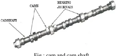
Fig : cam and cam shaft
Available online: https://edupediapublications.org/journals/index.php/IJR/ P a g e | 1029
opening, valve closing, and injection of fuel, and to increase power or to reduce cost, an engine may have one or more camshafts. Typically, in a medium to large V-type engine, each bank will have one or more camshafts per head. In the larger engines, the intake valves, exhaust valves, and fuel injectors may share a common camshaft or have independent camshafts. Depending on the type and make of the engine, the location of the camshaft or shafts varies. The camshaft(s) in an in-line engine is usually found either in the head of the engine or in the top of the block running down one side of the cylinder bank. When the piston travels below the level of the ports, the ports are "opened" and fresh air or exhaust gasses are able to enter or leave, depending on the type of port. The ports are then "closed" when the piston travels back above the level of the ports. Valves are mechanically opened and closed to admit or exhaust the gasses as needed. The valves are located in the head casting of the engine. The point at which the valve seats against the head is called the valve seat. Most medium-sized diesel engines have either intake valves or exhaust valves or both intake and exhaust valves.
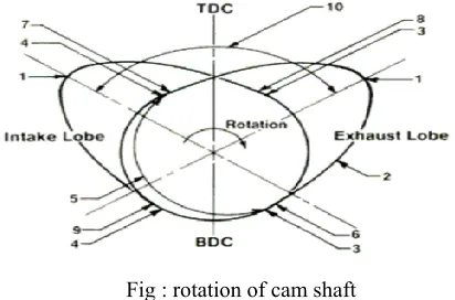
Fig : rotation of cam shaft
Cam is a mechanical member for transmitting a desired motion to a follower by direct contact. The driver is called cam and driven is called follower. Cam mechanism is a case of a higher pair with line contact. Camshaft is the Brain of the engine must include cam lobes, bearing journals, and a thrust face to prevent fore and after motion
Available online: https://edupediapublications.org/journals/index.php/IJR/ P a g e | 1030
locations and types and amount of the existent stress levels. Many studies have been carried out on the automotive failure analysis is that the mostly failed parts are from engine and its components among the automotive failures. This is followed by the drive train failures. Among the studies on the engine component failures, the prediction of fatigue failure in a camshaft using the crack-modeling method.
Camshaft is used in the engine for transfers motion to inlet & exhaust valve. If transfer of motion is not proper then the stokes will not work in proper way. Also it effects on performance of engine.To make work of camshaft in precise way. It is required in order to design a good mechanism linkage, the dynamic behavior of the components must be considered; This includes the gross kinematic motion and self-induced vibration motion. Dynamic models were created to obtain insight into dynamic behavior of the system prior to manufacturing. These models were mathematical tools used to simulate and predict the behavior of physical systems. They contain systems properties which are masses, stiffness constants, and damping coefficients. The automotive sector has reached a very high production capacity in the last decades. Depending on this increasing capacity, its stable growth is anticipated in the world economy. The economic value of the work capacity in the automotive sector is very large and this shows that the automotive sector is the 6th economic sector worldwide. The sector has an interrelationship with more than 300 different fields. So, if there is any malfunction in the main or side industries, the whole functions of the produced cars are influenced. On the other hand, the failure analysis is a special field of study for materials and mechanical engineers. On one side, the materials engineer is intended to develop his/her observational and reasoning skills for the understanding of interrelationship between
observable features and properties or performance. On the other side, the mechanical engineer studies on the possible failure locations and types and amount of the existent stress levels. Many studies have been carried out on the automotive failure analysis is that the mostly failed parts are from engine and its components among the automotive failures. This is followed by the drive train failures. Among the studies on the engine component failures, the prediction of fatigue failure in a camshaft using the crack-modeling method.
A camshaft is a pole to which a cam is affixed or of which a cam structures a vital part. The camshaft is the most vital part of an interior burning motor (internal combustion engine). Its primary capacity is to control the valve timing, along these lines permitting intake valve to open at the right time for feeding fuel and air mixture into the engine. The camshaft is driven by the motor's crankshaft through a progression of riggings called idler apparatuses and timing gears. The riggings permit the pivot of the camshaft to relate or be in time with the turn of the crankshaft and along these lines permit the valve opening, valve shutting, and infusion of fuel to be planned to happen at exact interims in the cylinder's travel. To build the adaptability in timing the valve opening, valve shutting, and infusion of fuel, and to expand control or to decrease cost, a motor may
Available online: https://edupediapublications.org/journals/index.php/IJR/ P a g e | 1031
cylinder goes underneath the level of the ports, the ports are "opened" and outside air or fumes gasses can enter or leave, contingent upon the kind of port. The ports are then "shut" when the cylinder goes back over the level of the ports. Valves are mechanically opened and shut to concede or deplete the gasses as required. The valves are situated in the head throwing of the motor. The time when the valve seats against the head is known as the valve situate. Most medium-sized diesel motors have either allow
valves or fumes valves or both admission and fumes valves.
CAMSHAFT OPERATION: Camshaft Operation:
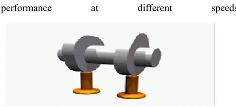
The camshaft uses lobes (called cams) that push against the valves to open them as the camshaft rotates; springs on the valves return them to their closed position. This is a critical job, and can have a great impact on an engine's
performance at different speeds
Fig 4 Cam shaft working
Uses of cam shafts:
In internal combustion engines with pistons mostly used in automotive industry, the camshaft is used to operate poppet valves. It consists of a cylindrical rod running the length of the cylinder bank with a number of oblong lobes protruding from it, one for each valve. The cam lobes force the valves open by pressing on the valve, or on some intermediate mechanism, as they rotate.
Position of cam shaft:
Depending on the location of the camshaft, the cam operates the valves either directly or through a linkage of
pushrods and rockers. Direct operation involves a simpler mechanism and leads to fewer failures, but requires the camshaft to be positioned at the top of the cylinders. In the past when engines were not as reliable as today this was seen as too much trouble, but in modern gasoline engines the overhead cam system, where the camshaft is on top of the cylinder head, is quite common.
Fig Position of cam shaft
TYPES OF CAMS HAFTS: Single Overhead Cam:
A single overhead cam has one cam per head. So if it is an inline 4-cylinder or inline 6-cylinder engine, it will have one cam; if it is a V-6 or V-8, it will have two cams (one for each head). On single and double overhead cam engines, the cams are driven by the crankshaft, via either a belt or chain called the timing belt or timing chain.
Double Overhead Cam:
A double overhead cam engine has two cams per head. So inline engines have two cams, and V engines have four. Usually, double overhead cams are used on engines with four or more valves per cylinder -- a single camshaft simply cannot fit enough cam lobes to actuate all those valves. The main reason to use double overhead cams is to allow for more intake and exhaust valves. More valves, means that intake and exhaust gases can flow more freely because there are more openings for them to flow through. This increases the power of the engine.
Camshaft Basics
Available online: https://edupediapublications.org/journals/index.php/IJR/ P a g e | 1032
exhaust valves in time with the motion of the piston. It turns out that there is a direct relationship between the shape of the cam lobes and the way the engine performs in different speed ranges. To understand why this is the case, imagine that we are running an engine extremely slowly -- at just 10 or 20 revolutions per minute (RPM) -- so that it takes the piston a couple of seconds to complete a cycle. It would be impossible to actually run a normal engine this slowly, but let's imagine that we could. At this slow speed, we would want cam lobes shaped so that: Just as the piston starts moving downward in the intake stroke (called top dead center, or TDC), the intake valve would open. The intake valve would close right as the piston bottoms out. The exhaust valve would open right as the piston bottoms out (called bottom dead center, or BDC) at the
end of
the combustion stroke, and would close as the piston completes the exhaust stroke. This setup would work really well for the engine as long as it ran at this very slow speed. But what happens if you increase the RPM? Let's find out. When you increase the RPM, the 10 to 20 RPM configuration for the camshaft does not work well. If the engine is running at 4,000 RPM, the valves are opening and closing 2,000 times every minute, or 33 times every second. At these speeds, the piston is moving very quickly, so the air/fuel mixture rushing into the cylinder is moving very quickly as well. When the intake valve opens and the piston starts its intake stroke, the air/fuel mixture in the intake runner starts to accelerate into the cylinder. By the time the piston reaches the bottom of its intake stroke, the air/fuel is moving at a pretty high speed. If we were to slam the intake valve shut, all of that air/fuel would come to a stop and not enter the cylinder. By leaving the intake
valve open a little
longer, the momentum of the fast-moving air/fuel continues to force air/fuel into the cylinder as the piston
starts its compression stroke. So the faster the engine goes, the faster the air/fuel moves, and the longer we want the intake valve to stay open. We also want the valve to open wider at higher speeds -- this parameter, called valve lift, is governed by the cam lobe profile.
COMPOSITE MATERIALS:
Available online: https://edupediapublications.org/journals/index.php/IJR/ P a g e | 1033
thermoplastic matrix.
The most primary applications of composite materials are found where high strength and low weight are concerned. Few properties of composites accounted for their wider uses are high strength, low density, high tensile strength at high temperatures, high toughness, and high creep resistance.
Metal Matrix Composites (MMC):
Metal matrix composites preferable instead of metals in few applications for the properties like High strength, low co-efficient of thermal expansion, less weight.
The composites which consist of metal alloys reinforced with continuous fibers or particulates I said to be MMC. These composites uses metals as matrix materials and they have a higher temperature resistance than PMCs but they in general are heavier. The basic merit of metals reinforced with hard ceramic particles or fibers are improved strength and stiffness. They also have improved creep and fatigue resistance, increased hardness, wear and abrasion resistance. MMC have wide range of applications in combustion chamber nozzle, housings, tubing, cables, heat exchangers, structural members due to their above properties.
scope of the project
The structural modeling of the Cam shaft needs to be developed by using solidworks design software. Then structural analysis and fatigue analysis are carried out in ansys and suitable materials such as genral and composite material are applied and began the meshing on the Cam shaft. The finite element modeling (fem) processes were performed. One end is fixed and loading is selected and placed at the other end of Cam shaft. The finite element analysis (fea) then carried out on the Cam shaft by dividing the larger solutions into smaller solutions in the form of partial differential equations.thus, producing the result of stress, strain and displacement where it will be
used to analyze the critical area of the Cam shaft and fatigue analysis tool life , damage and factor of safty is find out finaly conclude the best material based upon strength to weight ratio and life.
SOLIDWORKS
Solid Works is mechanical design automation software that takes advantage of the familiar Microsoft Windows graphical user interface.
It is an easy-to-learn tool which makes it possible for mechanical designers to quickly sketch ideas, experiment with features and dimensions, and produce models and detailed drawings.
A Solid Works model consists of parts, assemblies, and drawings.
MODELLING OF CAM SHAFT
Draw sketch as follows
Go to features and make revolve
Available online: https://edupediapublications.org/journals/index.php/IJR/ P a g e | 1034
Draw the remaining cams as above
Then draw the following sketch and make extrude
Four views of cam shaft
INTRODUCTION TO SIMULATION:
Simulation is a design analysis system. Simulation provides simulation solutions for linear and nonlinear static, frequency, buckling, thermal, fatigue, pressure vessel, drop test, linear and nonlinear dynamic, and optimization analyses.
Powered by fast and accurate solvers, simulation enables you to solve large problems intuitively while you design. Simulation comes in two bundles: simulation professional and simulation premium to satisfy your analysis needs. Simulation shortens time to market by saving time and effort in searching for the optimum design.
Fig: simulation example
FEM (Finite element method)
The software uses the finite element method (fem). Fem is a numerical technique for analyzing engineering designs. Fem is accepted as the standard analysis method due to its generality and suitability for computer implementation. Fem divides the model into many small pieces of
simple shapes called elements effectively replacing a complex problem by many simple problems that need to be solved simultaneously.
ANSYS Introduction
ANSYS delivers innovative, dramatic simulation technology advances in every major Physics discipline, along with improvements in computing speed and enhancements to enabling technologies such as geometry handling, meshing and post-processing. These advancements alone represent a major step ahead on the path forward in Simulation Driven Product Development.
Materials properties
Material properties used for analysis are as follow
Available online: https://edupediapublications.org/journals/index.php/IJR/ P a g e | 1035
3D Modal after part IGES file transferred to ansys workbench software
Fixed support
Cam shaft is fixed at one end
Load
500 N loads is applied on each cam.
Mesh
Uesd program controlled , tetrahedral shape and fine size mesh
Mesh quality
MATERIAL: Alloy steel (42CrMo4) Stress
Stress achieved after analysis for alloy steel material.
Strain
Strain achieved after analysis for alloy steel material.
Deformation
Deformation achieved after analysis for alloy steel material.
FATIGUE ANALYSIS Life
Available online: https://edupediapublications.org/journals/index.php/IJR/ P a g e | 1036 Damage
Damage of the cam shaft after analysis, for Alloy steel
Factor of Safety
Factor of safety of the cam shaft after analysis, for Alloy steel
MATERIAL: Aluminium Metal Matrix Stress
Stress achieved after analysis for Al metal matrix composite.
Strain
Strain achieved after analysis for Al metal matrix composite
Deformation
Deformation achieved after analysis for Al metal matrix composite
FATIGUE ANALYSIS Life
Life of the cam shaft after analysis, for Al metal matrix composite
Damage
Available online: https://edupediapublications.org/journals/index.php/IJR/ P a g e | 1037 Factor of Safety
Factor of safety of the cam shaft after analysis, for Al metal matrix composite
Results
Static Structural Results
:
Conclusion
Modeling and analysis of cam shaft is done.
Brief study about cam shaft, its applications, classification, and about composite materials is one in this project.
Modeling of cam shaft is done in solid works 2016 design software.
Static analysis is carried out in Ansys work bench16 by applying load on two different materials, one is generally used alloy steel material and another is Aluminium metal matrix composite material.
Structural deformations such as stress, deformation and strain are studied and tabulated.
In Fractural tool, Life, Damage and Factor of safety on each material is noted and tabulated.
From the results we can conclude that Aluminium Metal Matrix composite (KS1275) is showing less stress compare to Alloy steel (42CrMo4).
According weight Al metal matrix showing less weight compare to Alloy steel.
Meanwhile Aluminium metal matrix is showing high life and less damage than compare to alloy steel.
Hence we can conclude that Aluminium metal matrix is better material for cam shaft than compare to alloy steel material, due to its less weight to strength ratio, high strength , and better high life.
References
[1] G.Wang, D.Taylor, B Bouquin J Devlukia, “Prediction of fatigue failure in a camshaft using crack modeling method,”Elsevier,Vol7,189-197,2000
[2] Vivekanandan P, Kumar M, “ Modeling ,Design and Finite Element Analysis of Camshaft” IJCET, ISSN 2277-4106, vol-3, No.1 , 2013
[3]Santosh Patil,S.F.Patil and Saravanan Karuppanam “Modal and Fatigue analysis of a camshaft using FEA”IJAER,ISSN 0973-4562, vol-8,No.14, 2013
[4] V.Mallikarjun, N Jashuva ,G Nagaraju, “Design manufacturing and cost estimation of a camshaft used in two wheeler” , IOSR-JMCE, ISSN 2278-1684, vol.11, issue-1,Ver-IV,PP 53-67, 2014
[5]R.V.Wanjari, T.C.Parshiwanikar,“Design and analysis of camshaft by changing parameters which causes failure,”IJISME, ISSN:2319-6386,vol.1, Issue6, 2013. [6] R.V.Wanjari,T.C.Parshiwanikar,” Failure of camshaft“,IJITEE,ISSN:22783075,vol.2,Issue.6,2013 [7] Suhas K.F., Dr.Mohmmad Haneef,”Contact fatigue analysis using finite element analysis for 6 station lobe camshaft”,IJOAR, ISSN:2249-555,