Mitigation of Voltage Sags and Swells by using
Dynamic Voltage Restorer
Parul D. Oza1
PG Student [PEED], Dept. of EE, LCIT College, Bhandu, Gujarat, India1
ABSTRACT: Power Quality is an occurrence manifested as many type of disturbance in voltage current or frequency, sensitive industrial loads that results in failure of end user equipment. So this paper represents the techniques for improve in sag and swell using device like DVR. The Dynamic Voltage Restorer (DVR) is a series compensator which can compensate for power quality problems such as voltage harmonics, voltage unbalance, voltage flickers, voltage sags, and voltage swells. Among all these power quality problems, two are identified as the major concern to the customers namely voltage sag and swell. A control technique based on a proportional integral (PI) controller is implemented. In fact with the aid of Pulse width modulation (PWM) inverter capable of generating accurate high quality voltage waveforms from the power electronic device. Simulation result shown by MATLAB/Simulink.
KEYWORDS:power quality; voltage sag/swell; pulse width modulation; DVR; voltage source converter.
I.INTRODUCTION
Continuous production throughout the period is ensured only when the final objective is to optimize the production while achieving maximum profits and achieving minimized production cost. The reason for demanding high quality un-interruptible power during production process. As soon as the fault occurs the action of DVR starts. On event of fault which results in voltage sag, the magnitude reduction is accompanied by phase angle shift and the remaining voltage magnitude with respective phase angle shift is provided by the DVR. Employing minimum active voltage injection mode in the DVR with some phase angle shift in the post fault voltage can result in miraculous use of DVR. If active voltage is less prominent in DVR then it can be delivered to the load for maintaining stability.
1.1.Power Quality Problems
The IEEE defined power quality disturbances into seven categories based on wave shape: 1. Transients 2.Interruptions 3.Sag / under voltage 4.Swell / Overvoltage 5.Waveform distortion 6 .Voltage fluctuations 7.Frequency variations. Among all these power quality problems, two are identified as the major concern to the customers voltage sag and swell.
Voltage Sag:
IEEE standard sag can be define as the “A decrease to between 0.1 and 0.9 pu in rms voltage or current at the power frequency for durations of 0.5 cycles to 1 minute.” It caused by sudden increase in load such as short circuit or faults, turning on electric heater, motor starting.
Voltage Swell:
Voltage swell can define as the “An increase to between 1.1 pu and 1.8 pu in rms voltage or current at the power frequency durations from 0.5 cycles to 1 minute.” It caused by abrupt fall in load with poor voltage and also caused by loose or damage neutral connections.
II. PRINCIPLE AND OPERATION OF DVR
2.1. Principle
switching device consisting of either GTO or IGBT, a capacitor bank as an energy storage device and injection transformers. It is connected in series between a distribution system and a load that shown in Figure 1. The basic idea of the DVR is to inject a controlled voltage generated by a forced commuted converter in a series to the bus voltage by means of an injecting transformer. A DC capacitor bank which acts as an energy storage device, provides a regulated dc voltage source.
Fig.1 Principle of DVR with a response time of less than one millisecond
2.2 Components of DVR
A typical DVR consist of the following major components:
Fig.2 Simplified DVR blocks
1. DC Storage Device
It supply necessary energy to VSI during compensation. VSI will convert it into alternating quantity and fed to injection transformer
2. Voltage Source Inverter
VSI is power electronics system consist of switching device (IGBT, GTO) which can generate a sinusoidal voltage at any required frequency, magnitude and phase angle.
3. Filter Unit
The main task of filter is to keep the harmonic voltage content generated by VSI to the permissible limit (i.e. eliminate high frequency harmonics)
4. Voltage injection Transformers
It consist of two side one is high voltage side and low voltage side. The high voltage side is normally connected in series with distribution n/w while low voltage side is connected to DVR it isolate distribution line from DVR system. 5. Control System
6. PWM Generator
The PWM modifies the width of the pulses in a pulse train by using control signal. When the value of control voltage increases, it results wider pulses. The waveform of control voltage for a PWM circuit will determine the waveform of the produced voltage.
III.DVR COMPENSATION TECHNIQUES
The compensation control technique of the DVR is the mechanism used to track the supply voltage and synchronized that with the pre-sag supply voltage during a voltage sag/swell in the upstream of distribution line.
(i) Pre-sag Compensation
Pre-sag compensation is a method which is generally used for nonlinear loads such as thyristor controlled drives. In nonlinear loads the voltage magnitude as well as he phase angle needs to be compensated.
(ii)In-phase Compensation
This technique of compensation is generally used for active loads. Only compensation for voltage magnitude is required whereas no phase compensation is required. In this particular method the compensated voltage is in phase with the sagged voltage.
(iii)In-phase advanced compensation method
In this method the real power spent by the DVR is decreased by minimizing the power angle between the sag voltage and load current. In case of pre-sag and in-phase compensation method the active power is injected into the system during disturbances. The active power supply is limited stored energy in the DC links and this part is one of the most expensive parts of DVR.
(iv)Energy optimization technique
In this particular control technique the use of real power is minimized (or made equal to zero) by injecting the required voltage by the DVR at a 90° phase angle to the load current.
Fig.3 DVR compensation Techniques
IV. TEST SYSTEM AND SIMULATION RESULT
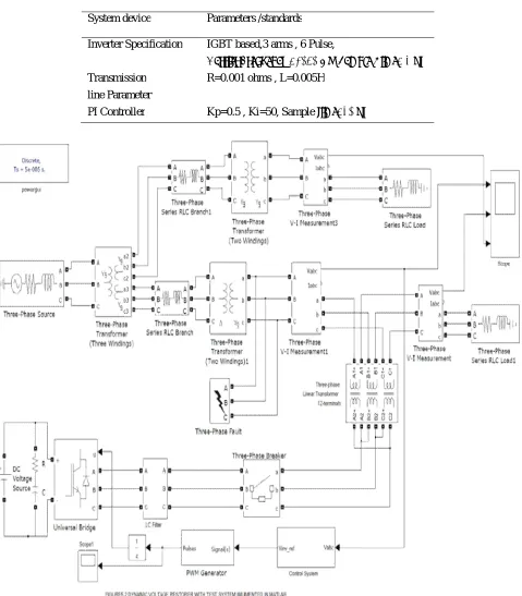
Table 1. System Parameter
System device Parameters /standards
Inverter Specification IGBT based,3 arms , 6 Pulse,
Carrier Frequency =1080 Hz, Sample Time= 5 μs Transmission
line Parameter
R=0.001 ohms , L=0.005H
4.1. Simulation Results for Sag: Three phase to ground Fault Sag
V.CONCLUSION
Dynamic voltage restorers (DVR) are used to protect sensitive loads from the effects of voltage sags/swells on the distribution feeder. In all cases it is necessary for the DVR control system to not only detect the start and end of a voltage sag but also to determine the sag depth and any associated phase shift. The DVR, which is placed in series with a sensitive load, must be able to respond quickly to voltage sag if end users of sensitive equipment are to experience no voltage sags. As conclusion, voltage sag/swell is unwanted phenomenon which unavoidable but can be reduced using all techniques, but not limited to the techniques that have been discussed. There is no one mitigation technique that will suitable with every application, and whilst the power supply utilities strive to supply improved power quality, it is up to the applications engineer to minimize power quality problems. It means, power quality problem cannot be eliminated but we can reduce and try to avoid this problem form occur.
REFERENCES
[1] C. Benachaiba and B. Ferdi, “Power Quality Improvement Using DVR”, American Journal of Applied Sciences, vol.6, no.3, 2009, pp. 396-400 .
[2] Joseph Seymour Terry Horsley, “The Seven Types of Power Problems”, American Journal of Power Conversion, 2005, pp.1-24.
[3] H.P. Tiwari, Sunil Kumar Gupta, “Dynamic Voltage Restorer Based On load Condition”, International Journal of Innovation, Management and Technology, vol.1 no.1, April 2010.
[4] K.Sandhya, Dr.A.Jaya Laxmi, Dr. M.P.Soni, “Direct and Indirect Control Strategies of Dynamic Voltage Restorer”, Proc. of Int. Conf. on Control, Communication and Power Engineering, 2010, pp.281-285.
[5] Arindam Ghosh and Gerard Ledwich, Senior Member IEEE, “Compensation Of Distribution System Voltage Using DVR”, IEEE Transaction On Power Delivery vol.17,no.4, 2002, pp.1030-1036.
[6] Rosli Omar, Nasrudin Abd Rahim and Marizan Sulaiman, “New Control Technique Applied in Dynamic Voltage Restorer for Voltage Sag Mitigation”, American Journal of Applied Sciences vol.3, 2010, pp.858-864.
[7] H.P. Tiwari and Sunil Kumar Gupta, “DC Energy Storage Schemes for DVR Voltage Sag Mitigation System”, International Journal of Computer Theory and Engineering, vol.2 No.3, June 2010, pp.313-318.