DSP-based Multiple Peak Power
Tracking
Himanshu Mehndiratta; Hitesh Gaba & Harsh Yadav
Department of ECE, Dronacharya College of Engineering, Gurgaon-123506, India
Email: [email protected]
Abstract:
A DSP-based improved most electric receptacle tracking (MPPT) approach for multiple electrical device application is conferred. It incorporates a “shared bus” current sharing method that may regulate several paralleled current mode DC/DC converters. The standard design eases the growth of system power. the present sharing and MPPT performance of the projected system is valid and evaluated by a 500-W prototype with 2 star arrays.
INTRODUCTION
As the would like for versatile, ascend able space-based power requirements will increase, and in an attempt to avoid plan of spacecraft and electrical propulsion power systems, a number of ideas have emerged to produce expandable, parallel connected power converters using techniques like maximum wall plug trailing (MPPT). Such approaches then permit a range of choices with the remainder of the ability system like using normal, modular, power converters that may be connected in parallel. The goal of such structures is to produce one power grid style that may meet a variety of power
MPPT management algorithmic program
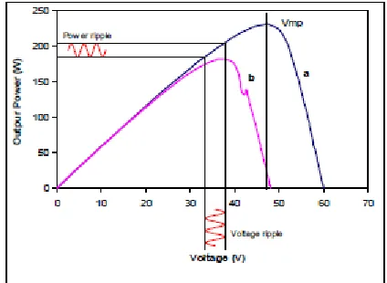
Curve as shown in Fig. one may be a typical P-V characteristic of a electrical device. Since the curve rely upon insolation, temperature conditions, and there's just one single purpose of operation that may extract most power from the array, therefore, MPPT ought to be enforced to trace the changes= and extract the utmost power from the electrical device. For a electrical device supply MPPT grid, followed DC/DC converters are typically operated in output voltage regulation mode once system-load demand is a smaller amount than array peak power. This typically moves the in operation purpose on the IV array graph to the correct aspect of the array peak power point wherever the array supply behaves the same as a voltage supply of low internal electric resistance. because the load increases, the electrical device in operation purpose moves up to the left along the array I-V characteristics till it reaches the maximum electrical outlet whereas the system output voltage remains regulated. while not MPPT management, once the load current is higher than the amount adore the array maximum power, the array I-V in operation purpose can move to the left of the utmost electrical outlet, inflicting the system output voltage to lose regulation. while not a correct controller design, the array voltage will collapse toward zero once load demand is higher than the utmost power of the array, particularly once supply a constant-power form of load. When properly applied, a MPPT management will stop the collapse of the array voltage below excessive load demand. One correct approach is to work the
system during a electrical device voltage regulation mode during which the array voltage is clamped to a commanding point, V mp , that is dynamically updated by the MPPT feedback loop. The control processes 2 feedback signals — the array current and the array voltage. Eventually, this endlessly updated set point can fluctuate round the voltage adore the array peak electrical outlet. By adjusting the in operation purpose of the array to the purpose V mp, power output of the array is maximized and also the best use of the electrical device could be accomplished.
Fig. Solar array characteristics
wide used approach to MPPT. As the name
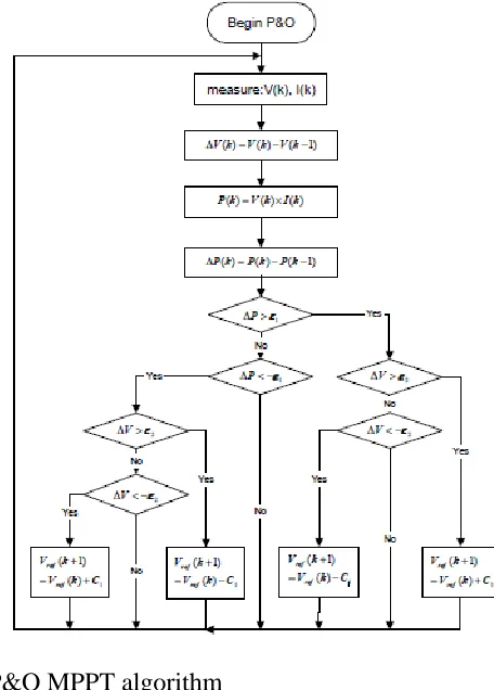
of the P&O technique states, this method works by perturbing the system by increasing or decreasing the array operating voltage and perceptive its impact on the array output power, as indicated in Fig. 1. Figure 2(a) shows a flow chart diagram of the P&O rule because it was enforced in the dominant micro chip. With this rule the in operation voltage is rattled with each MPPT cycle. As shortly because the MPP is reached, the output voltage of solar battery can oscillate round the ideal operating voltage V mp. This causes an influence loss that depends on the step breadth of one perturbation. The value for the perfect step breadth is system dependent and should be determined by experimentation to pursue the exchange of accrued losses underneath stable or slowly dynamic conditions. In fact, since the ac part of the output power signal is far smaller than the dc part and can contain a high noise level thanks to the switch DC/DC convertor, a rise in the amplitude of the modulating signal needs to be enforced to improve the signal to noise quantitative relation (SNR), however, this will lead to higher oscillations at the MPP and so increase power losses even underneath stable environmental conditions.
Flow chart of P&O MPPT algorithm and
IncCond MPPT algorithm
PARALLELED DC/DC CONVERTERS
The application of paralleling modules truly brings benefits within the following aspects: 1) lowering this stress on every single power semiconductor devices, therefore improves the thermal management and increase this output capability, 2) achieving supposed N+1 redundant and greatly improves the dependability of the ability supply; 3) providing additional flexibility for personalisation, eases the maintenance and repair, and scale back the athletics time. However, connecting converters in parallel additionally presents several new challenges. the most issue for the parallel connected converters is a way to distribute this uniformly among the converters. Currently, most of the approaches were principally supposed for uses in massive categories of power converters that typically don't exploit current mode control because the innermost basic management loops. When considering a way less complicated current sharing management approach, current mode controlled converters become terribly enticing. Although some approaches adopted current mode management as the innermost management loop, the more quality makes it unsuitable for expandable installation applications. In this paper, current mode converters are connected in parallel with current sharing bus, as shown in Fig. 4. It can be found once current sharing bus is inserted within the voltage regulation loop, it becomes the inner loop regulation structure for current sharing. The profit is that this sharing loop and current
CONCLUSION
An expandable facility with strong multiple power point trailing capabilities is conferred during this paper. The system incorporates a DSP controller to trace multiple peak power points of a plurality of star arrays. Paralleled current mode DC/DC converters, coupled between a star array and therefore the load acts as a peak power track module for every solar array. The performance of the planned system is validated and evaluated by a engineered 500W epitome.
REFERENCES
[1] Siri, K.; Conner, K.A. “Fault-tolerant scalable solar power bus architectures with maximum power tracking”. Applied Power Electronics Conference and Exposition, APEC 2001. Sixteenth Annual IEEE, Volume: 2, pp. 1009 -1014 vol.2. 2001
[2] Siri, K.; Conner, K.A. “Parallel-Connected Converters with Maximum Power Tracking”. Applied Power Electronics Conference and Exposition, APEC 2002. Seventeenth Annual IEEE, Volume: 1, pp. 419 -425 vol.2. 2002
[3] Hussein, K.H.; Muta, I.; Hoshino, T.; Osakada, M. “Maximum photovoltaic power tracking: an algorithm for rapidly changing atmospheric conditions”, Generation, Transmission and Distribution, IEE Proceedings, Volume: 142 Issue: 1 Jan. pp. 59 –64, 1995
[4] Koutroulis, E.; Kalaitzakis, K.; Voulgaris, N.C., “Development of a micro-controller-based, photo voltaic maximum power point tracking control system”, Power Electronics, IEEE Transactions on, Volume: 16 Issue: 1, pp. 46 –54, Jan. 2001
[5] Tse, K.K.; Chung, H.S.H.; Hui, S.Y.R.; Ho, M.T. “A novel maximum power point tracking technique for PV panels”, Power Electronics Specialists Conference, 2001. PESC. 2001 IEEE 32nd Annual, Volume 4, pp. 1970 –1975, 2001
[6] Yeong-Chau Kuo; Tsorng-Juu Liang; Jiann-Fuh Chen “Novel maximum-power-point-tracking controller for photo voltaic energy conversion system”, Industrial Electronics, IEEE Transactions on, Volume: 48 Issue: 3, pp. 594 –601, June 2001