Shielding analyses of an AB-BNCT facility using Monte Carlo
simulations and simplified methods
Bo-Lun Lai1 and Rong-Jiun Sheu2,*
1Institute of Nuclear Engineering and Science, National Tsing Hua University, 101, Sec. 2, Kuang-Fu Road, Hsinchu 30013, Taiwan 2Department of Engineering and System Science, National Tsing Hua University, 101, Sec. 2, Kuang-Fu Road, Hsinchu 30013, Taiwan
Abstract. Accurate Monte Carlo simulations and simplified methods were used to investigate the shielding requirements of a hypothetical accelerator-based boron neutron capture therapy (AB-BNCT) facility that included an accelerator room and a patient treatment room. The epithermal neutron beam for BNCT purpose was generated by coupling a neutron production target with a specially designed beam shaping assembly (BSA), which was embedded in the partition wall between the two rooms. Neutrons were produced from a beryllium target bombarded by 1-mA 30-MeV protons. The MCNP6-generated surface sources around all the exterior surfaces of the BSA were established to facilitate repeated Monte Carlo shielding calculations. In addition, three simplified models based on a point-source line-of-sight approximation were developed and their predictions were compared with the reference Monte Carlo results. The comparison determined which model resulted in better dose estimation, forming the basis of future design activities for the first AB-BNCT facility in Taiwan.
1 Introduction
Boron neutron capture therapy (BNCT) is a form of targeted radiotherapy that relies on the thermal neutron capture reaction of boron-10, leading to two heavy charged particles to kill only boron-compound-bearing cells while sparing other surrounding tissues. It is an ideal selective form of radiotherapy if a high ratio of boron concentration between tumor and normal tissues could be achieved. The method could also be used to treat deeper-seated tumors in patients by using epithermal neutron beam. The Tsing Hua Open-Pool Reactor (THOR), a 2 MW research reactor located at the campus of National Tsing Hua University in Taiwan, has been successfully upgraded and renovated for BNCT application in 2004 [1]. Clinical trials for patients with locally recurrent head and neck cancer were started since August 1, 2010 [2]. Until now, more than 20 patients have been treated with BNCT and the overall response is encouraging.
THOR has been used for over 50 years and now is operating under its second licence extention. The BNCT group in Taiwan is seeking to establish an accelerator-based BNCT (AB-BNCT) facility to continue and expand this area of research. One major advantage of AB-BNCT over traditional reactor-based facilities is the public acceptance of sitting in a densely populated hospital. The proposed AB-BNCT facility in Taiwan is similar to the cyclotron-based neutron source at KURRI [3], where neutrons are produced from the bombardment of a beryllium target by 1-mA 30-MeV protons. To deliver high-quality epithermal neutron beam, the
emitted fast neutrons from the target will be moderated by a specially designed beam shaping assembly (BSA) composed of iron, lead, polyethylene, bismuth and FLUENTALTM [4]. This study aimed at investigating the
characteristics of radiation field and bulk shielding requirements of such a facility.
2 Materials and methods
2.1 Facility and shielding layout
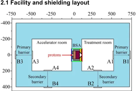
Fig. 1. Layout of a simple AB-BNCT facility, showing the bulk shielding structure and several locations of interest (A1-A4, B1-B4) inside and outside the concrete walls of the two rooms.
abscissa and ordinate are the distance with unit of centimetre. During normal operation, a monoenergetic 30-MeV proton beam of 1-mA was launched to impinge on a beryllium target located inside the BSA. The cylindrical-shaped BSA with overall dimensions of 160 cm diameter and 125 cm length was entirely embedded in the partition wall (1.25 m thick) between the two rooms to reduce leakage radiation and simplify shielding design. The inner dimensions of the treatment room and accelerator room were 4×4×3 m3 and 5×4×3 m3,
respectively. The thickness of the concrete wall was initially assumed to be 2 m, with a goal of reducing the transmitted dose rates to less than 10 μSv/h during normal operation. The primary barriers in Fig. 1 are referred to the walls directly facing the beam exit or entrance of the BSA where the radiation is expected to be the most intense, and the lateral concrete walls are called secondary barriers. Eight thin rectangles in Fig. 1 labelled A1 to A4 and B1 to B4 show the locations of scoring detectors, indicating typical radiation levels inside and outside the shielding structure during beam irradiation.
2.2 Calculation methods
The multi-particle Monte Carlo transport code MCNP6 [5] was used to simulate the proton-induced nuclear interactions and the subsequent transport of secondary particles. The major advantage of using MCNP6 in this study is the accuracy of the underlying cross sections for proton and neutron transport. Neutron and photon flux distributions were scored at locations of interest and converted to dose rates by folding with the ICRP-74 ambient dose equivalent conversion factors [6].
Two types of Monte Carlo shielding calculations were performed. The first type was a direct simulation of the radiation environment around the whole facility. The results were taken as the reference for comparison. The second type was a series of simulations of radiation transport in simplified configurations, aiming to generate shielding parameters for use with the point-source line-of-sight approximation [7, 8]. Eq. (1) is a classical two-parameter attenuation formula of the model, where H is the transmitted dose at the position of interest, Ep is the proton energy, θ is the angle with respect to the beam direction, d is the effective thickness of the shield, r is the distance between the target and the detector, H0 and λ are the fitted parameters representing a pseudo-source term and the corresponding attenuation length under the specified conditions.
) ) , ( exp( ) , ( ) / , ,
( 0 2
θ λ θ
λ θ
p p
p
E d r
E H d
E
H = − (1)
Applying a point-source line-of-sight model for estimating dose rates outside thick shields of an AB-BNCT facility was anticipated to be problematic because of the existence of the large-sized and complicated BSA enclosing the neutron production target. In addition, as shown in Fig. 1, the whole BSA including the target was embedded in the partition wall of two rooms.
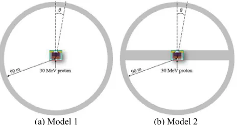
Considering these problems, this study took an approach of regarding the whole BSA as a radiation source in shielding analyses rather than a neutron-modifying device. In addition, as shown in Fig. 2, we considered two different geometries to generate shielding parameters, without and with the inclusion of the partition wall in the model. A coupling technique called the surface source write and read (SSW/SSR) in MCNP6 was implemented on the exterior surfaces of the BSA to reduce the computing burden of source generation in repeated Monte Carlo shielding simulations [5]. Note that the shielding parameters generated in this way were obviously the BSA dependent and intended only for use in shielding analyses of this facility.
(a) Model 1 (b) Model 2
Fig. 2. Two simplified spherical geometries used to generate shielding parameters for the AB-BNCT facility in this study.
3 Results and discussion
3.1. Radiation field around the BSA
The design of BSA aims at production of an optimal epithermal neutron beam for BNCT purpose. A common definition for an epithermal energy range is 0.5 eV to 10 keV. The BSA not only is a critical component for the performance of neutron beam, but also plays an essential role in subsequent shielding analyses. In addition to the nearly collimated neutrons from the exit of the BSA, there are significant amounts of neutrons and photons emerging from all surfaces of the BSA. Appropriate shielding against these unwanted radiation sources is important that must be considered as an integral part of the overall facility design.
included in shielding calculations via the use of the SSW/SSR technique in MCNP6.
10-9 10-8 10-7 10-6 10-5 10-4 10-3 10-2 10-1 100 101 102
0 1x10⁹
2x10⁹ 3x10⁹
Back surface Lateral surface (x101
) Front surface (x102)
Fl
ux per
l
et
h
ar
gy (cm
-2 s -1 )
Neutron energy (MeV)
Fig. 3. Neutron spectra emerged from the front, lateral and back surfaces of the BSA under the irradiation of 1-mA 30-MeV proton beam on the beryllium target.
3.2 Monte Carlo simulations
Based on the shielding model in Fig. 1, Table 1 lists the MCNP6-predicted neutron and photon dose rates at several locations around the facility. Overall, the dose rates around the accelerator room are higher than those around the treatment room by about three orders of magnitude. This is because the radiation leaking from the back surface of the BSA is substantially more intense than that emerging from the front surface and more importantly with much higher neutron energies (Fig. 3). Inside the treatment room, neutron dose rates are higher than photon dose rates by approximately a factor of 4. This factor increases to ~40 in the accelerator room. Outside the shielding rooms, neutron dose rates are roughly comparable to photon dose rates. One of the advantages using SSW/SSR in this case was the saving of computing time while preserving the accuracies of full-scale Monte Carlo simulations. According to our experience, if only the shielding analysis of the treatment room is concerned, performing transport calculations based on the MCNP6-generated source term from the front surface of the BSA is good enough. Similarly, using only the source term from the back surface should be appropriate for shielding analyses of the accelerator room.
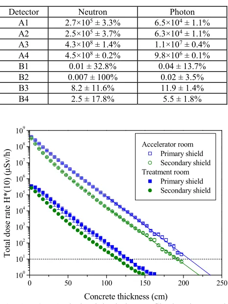
Fig. 4 shows the MCNP6-calculated depth dose profiles in primary and secondary barriers of the two rooms. From these trends, one can readily determine the required thicknesses of surrounding concrete walls to meet a prescribed dose limit. If a dose rate limit of 10 μSv/h is desired, the thicknesses of the primary and secondary barriers of the treatment room should be at least 128 cm and 114 cm, respectively. More shielding is required for the accelerator room because of the radiation distribution around the BSA. According to Fig. 4, at least 207 cm thick primary barrier and 192 cm thick secondary barrier are necessary to meet the same dose criterion. Although different thicknesses of concrete were required for these shielding walls, the attenuation
lengths fitted for concrete thicker than 100 cm in Fig. 4 were found varying in a small range of 28−32 g/cm2.
Table 1. MCNP6-predicted neutron and photon dose rates (μSv/h) at several locations around the facility (See Fig. 1).
Detector Neutron Photon
A1 2.7×10⁵ ± 3.3% 6.5×10⁴ ± 1.1%
A2 2.5×10⁵ ± 3.7% 6.3×10⁴ ± 1.1%
A3 4.3×10⁸ ± 1.4% 1.1×10⁷ ± 0.4%
A4 4.5×10⁸ ± 0.2% 9.8×10⁶ ± 0.1%
B1 0.01 ± 32.8% 0.04 ± 13.7%
B2 0.007 ± 100% 0.02 ± 3.5%
B3 8.2 ± 11.6% 11.9 ± 1.4%
B4 2.5 ± 17.8% 5.5 ± 1.8%
0 50 100 150 200 250
100 101 102 103 104 105 106 107 108 109
Accelerator room Primary shield Secondary shield Treatment room
Primary shield Secondary shield
T
o
ta
l do
se
ra
te
H*
(10
)
(
μ
Sv
/h
)
Concrete thickness (cm)
Fig. 4. MCNP6-calculated depth dose profiles in primary and secondary shields of the two rooms (See Fig. 1).
3.3 Point-source line-of-sight estimation
3.3.1 Source terms and attenuation lengths
The key for a successful use of a point-source line-of-sight model in shielding analysis relies on whether the source term and attenuation length are suitable to the problem under consideration. For the specific BSA designed for our facility, we have to generate associated shielding parameters by our own. As shown in Fig. 2, the authors adopted a similar calculation model used by Agosteo et al. [7]. The facility geometry was not modelled, but a simple spherical shell of concrete was placed around the BSA. MCNP6 was employed to simulate the proton-induced secondary radiation and their subsequent transport in surrounding concrete. Total dose rates including neutron and photon contributions were scored at given angular intervals and at various depths in concrete.
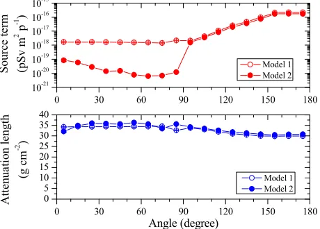
generated by the two models revealed certain characteristics of the radiation field around the BSA. The source terms of Model 1 (without the partition wall) exhibited a general slightly increasing trend as the angle increases because of significant leakage radiation in backward directions. Due to the shielding effect of the partition wall against strong radiation in the accelerator room, the source terms of Model 2 were apparently smaller than those of Model 1 for the entire forward hemisphere, facing toward the treatment room.
The previous curve fitting was performed only for depths greater than 100 cm in shield that exhibited a better exponential attenuation in dose profiles. The results in Fig. 5 indicate a relatively constant attenuation length, ranging within 30−36 g/cm2 for various angles
and for the two geometrical models, with and without the partition wall. This suggests the thick-shield attenuation length in this case is mostly a material property rather than depending on the energy distribution of incident neutrons. This is because most neutrons in deep shielding regions have reached an approximate equilibrium spectrum.
0 30 60 90 120 150 180
0 5 10 15 20 25 30 35 40
Model 1 Model 2
Att
e
n
ua
ti
on le
ngth
(g cm
-2 )
Angle (degree)
0 30 60 90 120 150 180
10-21
10-20 10-19 10-18 10-17 10-16 10-15
Model 1 Model 2
S
ource
te
rm
(pSv m
2 p -1 )
Fig. 5. Source terms and attenuation lengths as a function of angle for concrete shielding against 30-MeV protons hitting the beryllium target in the BSA.
3.3.2 Shielding requirements
Using Eq. (1) and the MCNP6-generated source terms and attenuation lengths, one can quickly estimate the transmitted dose rate at any position outside the shielding walls of the facility in Fig. 1. The results can be compared and verified with previous Monte Carlo predictions.
By using various approaches, Table 2 summarizes the estimated thicknesses of both primary and secondary barriers that are adequate to restrict dose-rates outside the facility to less than 10 μSv/h. Note that Models 1 and 2 estimated thicknesses of concrete walls based on different sets of shielding parameters, without and with considering the effect of the partition wall, respectively. Model 1 obviously overestimated the shielding requirements of the treatment room because of the inclusion of significant radiation backscattered from the accelerator room. As expected, Model 2 gave a more satisfactory prediction than Model 1 on the required
thickness of the primary shield of the treatment room because of a more realistic geometry used in parameter generation. However, both Models 1 and 2 failed to predict the correct thicknesses of two secondary barriers. This was somewhat anticipated because the point-source line-of-sight approximation tends to underestimate the transmitted dose rates at large slant angles. It is a well-known caveat when using this approximation in dose rate assessment, resulting from the long slant path of direct penetration in shield and an inappropriate treatment of radiation scattering.
In order to partly address this issue, we developed Model 3, which is essentially a different application of the shielding parameters in Model 2. To estimate the dose rates outside the shielding walls, say at B1−B4, the dose rates on the inner surface of the shield, i.e. at A1−A4, were estimated first by directly attenuating the source term of the given angle with an inverse-square law. In addition to the geometric attenuation, the material attenuation was then taken into account only the perpendicular thickness of the concrete wall. For simplicity, the average attenuation length in Fig. 5 was always used in the dose estimation of Model 3 regardless of the angle at which the dose point views the target. The result turned out to be satisfactory if compared with the Monte Carlo prediction, as indicated in Table 2.
Table 2. Comparison of the estimated thicknesses (cm) of primary and secondary shields of the AB-BNCT facility by using Monte Carlo simulations and three simplified methods.
Method Accelerator room Treatment room Primary Secondary Primary Secondary
MCNP6 207 192 128 114
Model 1 209 157 166 145
Model 2 211 158 114 84
Model 3 198 203 129 120
4 Conclusions
Acknowledgments
The work is financially supported by Industrial Technology Research Institute in Taiwan under contract no. 100A0303K8.
References
1. Y.W.H. Liu, T.T. Huang, S.H. Jiang, H.M. Liu, Appl. Radiat. Isotopes 61, 1039 (2004).
2. L.W. Wang, S.J. Wang, P.Y. Chu, C.Y. Ho, S.H. Jiang, Y.H. Liu, Y.W.H. Liu, H.M. Liu, J.J. Peir, F.I. Chou, S.H. Yen, T.L. Lee, C.W. Chang, C.S. Liu, Y.W. Chen, K. Ono, Appl. Radiat. Isotopes 69, 1803 (2011).
3. H. Tanaka, Y. Sakurai, M. Suzuki, S. Masunaga, Y. Kinashi, G. Kashino, Y. Liu, T. Mitsumoto, S. Yajima, H. Tsutsui, A. Maruhashi, K. Ono, Nucl. Instrum. Meth. B 267, 1970 (2009).
4. S. Yang, The beam shaping assembly and collimator design of epithermal neutron beam and in-phantom dose analysis for AB-BNCT (National Tsing Hua University, Master Thesis, 2014)
5. T. Goorley, et al., Nucl. Technol. 180, 298 (2012). 6. ICRP Publication 74, Conversion coefficients for
use in radiological protection against external radiation (Pergamon Press, 1996).
7. S. Agosteo, M. Magistris, A. Mereghetti, M. Silari, Z. Zajacova, Nucl. Instrum. Meth. B 265, 581 (2007).