555-233-754
Comcode 108678806
Issue 1
April 2000
Release 8.2
Every effort was made to ensure that the information in this book was complete and accurate at the time of printing. However, information is subject to change.
Your Responsibility for Your System’s Security
Toll fraud is the unauthorized use of your telecommunications system by an unauthorized party, for example, persons other than your com-pany’s employees, agents, subcontractors, or persons working on your company’s behalf. Note that there may be a risk of toll fraud associated with your telecommunications system and, if toll fraud occurs, it can result in substantial additional charges for your telecommunications services.
You and your system manager are responsible for the security of your system, such as programming and configuring your equipment to pre-vent unauthorized use. The system manager is also responsible for reading all installation, instruction, and system administration docu-ments provided with this product in order to fully understand the fea-tures that can introduce risk of toll fraud and the steps that can be taken to reduce that risk. Lucent Technologies does not warrant that this product is immune from or will prevent unauthorized use of com-mon-carrier telecommunication services or facilities accessed through or connected to it. Lucent Technologies will not be responsible for any charges that result from such unauthorized use.
Lucent Technologies Fraud Intervention
If you suspect that you are being victimized by toll fraud and you need technical support or assistance, call Technical Service Center Toll Fraud Intervention Hotline at 1 800 643-2353.
Federal Communications Commission Statement
Part 15: Class A Statement. This equipment has been tested and
found to comply with the limits for a Class A digital device, pursuant to Part 15 of the FCC Rules. These limits are designed to provide reason-able protection against harmful interference when the equipment is operated in a commercial environment. This equipment generates, uses, and can radiate radio-frequency energy and, if not installed and used in accordance with the instructions, may cause harmful interfer-ence to radio communications. Operation of this equipment in a resi-dential area is likely to cause harmful interference, in which case the user will be required to correct the interference at his own expense.
Part 68: Network Registration Number. This equipment is registered
with the FCC in accordance with Part 68 of the FCC Rules. It is identi-fied by FCC registration number AS593M-13283-MF-E.
Part 68: Answer-Supervision Signaling. Allowing this equipment to
be operated in a manner that does not provide proper answer-supervi-sion signaling is in violation of Part 68 Rules. This equipment returns answer-supervision signals to the public switched network when:
• Answered by the called station • Answered by the attendant
• Routed to a recorded announcement that can be administered by the CPE user
This equipment returns answer-supervision signals on all DID calls forwarded back to the public switched telephone network. Permissible exceptions are:
• A call is unanswered • A busy tone is received • A reorder tone is received
Le Présent Appareil Nomérique n’émet pas de bruits radioélectriques dépassant les limites applicables aux appareils numériques de la class A préscrites dans le reglement sur le brouillage radioélectrique édicté par le ministére des Communications du Canada.
Trademarks
See the preface of this document.
Ordering Information
Call: Lucent Technologies BCS Publications Center
Voice 1 800 457-1235 International Voice 317 322-6416 Fax 1 800 457-1764 International Fax 317 322-6699
Write: Lucent Technologies BCS Publications Center 2855 N. Franklin Road
Indianapolis, IN 46219
Order: Document No. 555-233-754 Comcode 108678806 Issue 1, April 2000
You can be placed on a standing order list for this and other documents you may need. Standing order will enable you to automatically receive updated versions of individual documents or document sets, billed to account information that you provide. For more information on stand-ing orders, or to be put on a list to receive future issues of this docu-ment, contact the Lucent Technologies Publications Center.
European Union Declaration of Conformity
The “CE” mark affixed to the DEFINITY® equipment described in this book indicates that the equipment conforms to the following Euro-pean Union (EU) Directives:
• Electromagnetic Compatibility (89/336/EEC) • Low Voltage (73/23/EEC)
• Telecommunications Terminal Equipment (TTE) i-CTR3 BRI and i-CTR4 PRI
For more information on standards compliance, contact your local dis-tributor.
Comments
To comment on this document, return the comment card at the front of the document.
Acknowledgment
Contents
Contents iii
New Switch and Adjunct Support 1
About this Document 1
■ Overview 2
DEFINITY® Enterprise Communications Server
Release 8 2
Release 8.1 Feature List 3
Release 8.2 Feature List 5
■ Platform - Enhancements/Renewal 7
DADMIN LOGIN 7
Optical Drive (TN2211) 8
U.S. Analog Trunk & Line Circuit Pack TN797 14
TN2313 DS1 Interface (US (24-Channel) or
International (32-Channel)) 14
24 Port Analog Line with Caller ID: TN793B
& TN2793B 15
■ General Telephony Enhancements - Global 16 Coverage of Calls Redirected Off-Net (CCRON) 16
13-Digit Authorization Codes 22
Auto Exclusion 25
64 Bridged Call Appearances 27
Circular Station Hunting 27
Group Call Pick-up 28
Long Hold Recall – Warning 28
Reset Shift Call 28
Station Self Display 28
Special Dial Tone [China] 28
6200 Analog Native Support 29
6400 Tip/Ring (Data Module Features) 34
Abort Transfer 43
Attendant Vectoring 45
Trouble Isolation: List Trace Command 55
■ NewHospitality-Related Features 62 Auto Selection Direct Inward Dial (DID) Numbers 62
Check In via the Hunt-To Feature 70
■ New Mobility-Related Features 73
X-Station Mobility (DECT) 73
XStation Mobility (MWL) 77
■ Telephony Applications - International 91
Reset Shift Call 91
■ Call Center 96
Overview 96
Call Center Release Control 98
Call Center - ASAI Trunk Group Identification 99
Call Center – ASAI/CTI Pending Work Mode
Changes 100
CALLMASTER V (Call Center 6416D+) Native
Support 101
Call Center - ASAI Capacity Increases for
Multiple Application Support 101
Call Center-Logged in Advocate Agent Counting 104
ATM_CMS 104
CMS High Availability 109
PC Application Software Translation Exchange
(PASTE) Update 111
Networking Enhancements 113
■ Networking - International 113
Continuous and Pulsed E&M Signaling (Brazil) 113
China Howler After Busy & Disconnect on No
Answer 118
Time Supervision & Force Release (China) 121
Administrable Loss Plan 125
■ Networking - ISDN Private 133
QSIG Call Independent Signaling Connection
(CISC) Enhancements 133
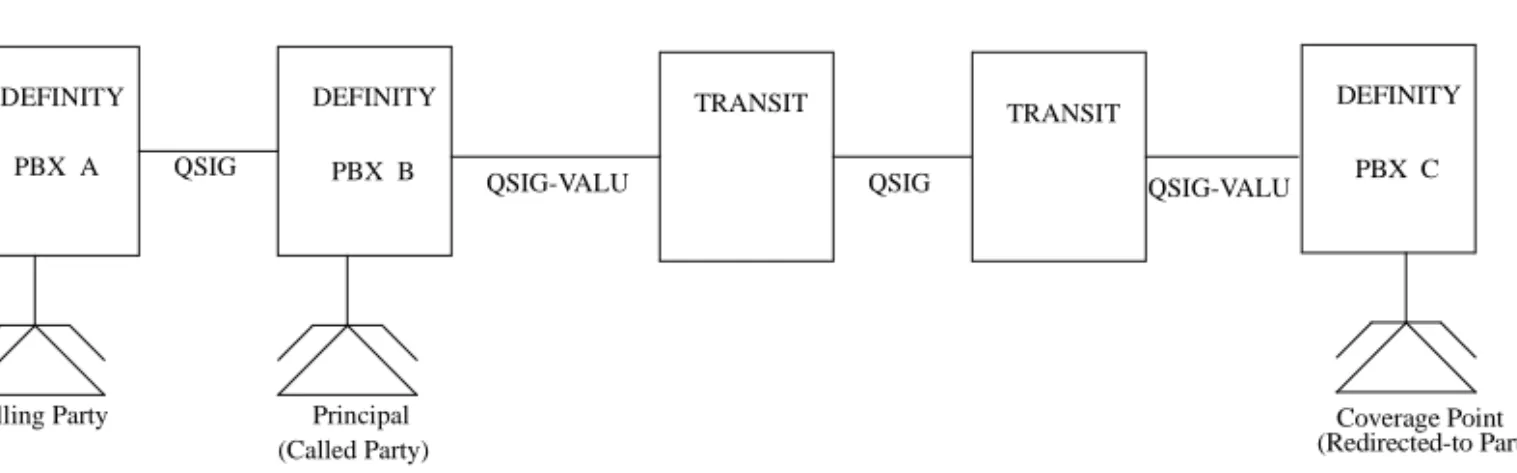
QSIG VALU Call Coverage 136
QSIG Integration: Transfer to Audix 141
QSIG CAS & VALU Coverage Interaction Support 144
QSIG CAS Enhancement 146
Centralized Voice Mail Via Mode Code 148
■ Networking - ISDN Public 155
BellCore Calling Name ID 155
Bellcore National ISDN Calling Name
Supplementary Service for PRI 156
Feature Plus – Non-DID Calling via UDP 160
Multiple Pubnet Calling/Connect Numbers/
System (Italy) 163
Pass Advice of Charge (AOC) to BRI Endpoints 172
Restricted Presentation 179
■ IP Solutions 186
TCP/IP-Connected Trunks 186
H.323 Trunk Administration 187
DEFINITY Internet Protocol (IP) Softphones 192
Adding a DEFINITY IP Softphone 196
IP Support Hardware 199
■ Networking - ATM 211
ATM Hardware 213
Administering ATM-CES amd ATM-PNC 214
Additional DEFINITY ECS administration 234
ATM PNC Reliability 244
Interworking with Bandwidth Constricted ATM
Networks 249
T1 401A/E1 402A/E1 403A Synchronization
1
New Switch and Adjunct Support
About this Document
This document introduces new and enhanced features and capabilities of DEFINITY Enterprise Communications Server (ECS) Release 8. It does not contain comprehensive instructions for switch administration or complete feature descriptions, nor does it contain information about how to install, maintain, repair, or troubleshoot the switch.
It is intended for DEFINITY system administrators and managers, users interested in information about specific features, and Lucent Technologies personnel responsible for planning, designing, configuring, selling, and supporting the system.
Overview
DEFINITY
®Enterprise Communications Server
Release 8
■ DEFINITY® ECS Release 8 is the next step in the evolution of the
DEFINITY® ECS.
■ It is a multi-purpose platform developed to support a number of offers.
■ It builds upon existing capabilities of the DEFINITY® ECS standard and
special development releases to implement cost reductions for Lucent Technologies, and a new set of advanced capabilities for the global communications marketplace.
■ Release 8 introduces these major features:
— Completion of C-LAN
— QSIG CAS enhancements
— ATM enhancements
— ASAI enhancements
— Call center enhancements
— IP Solutions
— Centralized Voice Mail via Mode Code
— Attendant Vectoring
Upgrades
Paths
R8 is an upgrade path for existing DEFINITY® system customers.
■ From pre-R5 to R8
■ From R5, R6, and R7 to R8 (through R5.5 for si customers with critical
reliability configurations)
■ Between specific R8 models
NOTE:
There are no upgrade paths for:
■ Non-csi models to csi models
Release 8.1 Feature List
CCRON Renewal
De-admin Login
Abort Xfer
13 Digit Auth Codes
X-station Mobility
DECT Support
Message Waiting Enhancement
6400 Tip/Ring Data Module
QSIG CISC Enhancements
■ Status Signaling Group
QSIG VALU Enhancements
■ Call Coverage
■ Distinctive Alerting
■ Call Coverage and CAS
Feature + non DID via UDP
BCS/Guestworks Enhancement
■ Auto digit rotation for DID
■ Crisis Alert to Pager
■ Suite Check in Via Hunt To Feature
ISDN Bellcore call-ID
E&M Signaling Enhancements
■ Brazil Contin. E&M Signal
■ Brazil Pulsed E&M Signal
■ Hungary Signal
ATM Network Duplication
6200 Analog Native Support
GTS Restricted Presentation
Australian CIN Board Support
Italy Multi Pub Net Calling – Connect Number/System
Pass AOC to BRI Endpoints
China Outgoing Call No Answer
China Time Super. and Force Release
Auto Exclusion by COS
INS l500-AOC
Fast Analog Modem Support Testing
Enhanced Terminal Parameters
G3R EMC Compliance
TN746B Buffer FW Changes
Advocate Enhancements
■ Logged-in Agent Counting
■ Standard Reports
ASAI/CTI Enhancements
■ CTI Regression Testing
■ Pending Work Mode Changes
■ Switch SW Version Query
■ Trunk Group ID in Event Reports
■ Cap Increase - Active Route Requirements
■ Cap Increase - Split Skill Dom Ctrl
■ UUI>32byte
Interworking Bandconstr (ATM)
ACD/ATM Capacity Increases
■ Hunt Group Members
■ Hunt Groups
■ Measure VDNs
■ QueueS1ots
■ Vectors
■ 1000 Announcements
CMS ATM Trk Measurements
Site Stats Remote EPN
Call Master V Native Support
CMS High Avail. Support
Call Center Release Control
Release 8.2 Feature List
TN799B
■ Variable Length Pin
■ TraceRoute
■ Packet Error History
■ SNMP Re-arch
■ Host Route Admin Chan Cs
TN2211 Optical Drive
■ UN332C MSSNET
IP Solutions
■ IP SoftPhones
■ H.323 Trunks
ATM PNC Reliability
QSIG Integration: Transfer to Audix
Attendant Vectoring (formerly CAS)
QSIG CAS & VALU Coverage Interaction Support
QSIG CAS Enhancement
■ Attendant Display of COR
■ Attendant Return of Call
■ Display Enhancements
■ Priority Queue
■ RLT Emulation via PRI
Support for Japan National Private Networking
■ 2MB Trunk — Ph 2: Codeset 5 TCMs
■ 2MB Trunk — Ph 2: Connect Ack
■ 2MB Trunk — Ph 2: Different Protocol Discriminator
■ D Channel — Private ISDN Networks — Q.931.a, Q.932.a
■ D Channel — Private ISDN Networks — 951.a
Administrable Loss Plan
24 Port Analog Line with Caller ID (TN793/TN2793B)
Centralized Voice Mail via Interswitch Mode Code
Trouble Isolation: List Trace Command
TN2313
T1 401A Sync Splitter
E1 402A Sync Splitter
Platform - Enhancements/Renewal
DADMIN LOGIN
■ Administration of the dadmin login uses the standard DEFINITY® login and
permission form interfaces.
■ Dadmin Login replaces Inads Login for Distributors.
■ The dadmin login ID, restricts access to commands that are limited to
Lucent Services.
■ The dadmin login service level is located between the inads and craft
logins service levels in the system administration/maintenance login permission hierarchy.
Restart Strategy for Dadmin Login
■ Login administration parameters are retained for the dadmin login on
recovery level 1 (warm) and recovery level 2 (cold) restarts and require retrieval from a translation storage device for all other restart levels.
*The maximum number of logins does not include the “mis” login which is used internally by the system to establish connections to call management systems, CMS.
Number of Logins
Platform Maximum Number of
Logins *
Login Distribution
R8(vs/si/csi) 16 ■ 4 Lucent Services Logins
■ 1 Dadmin Login
■ 11 Customer Logins
R8(r) 25 ■ 4 Lucent Services Logins
■ 1 Dadmin Login
Feature to Feature Interactions
Access Security Gateway (ASG)
■ ASG authentication not required by default for the dadmin login.
■ ASG field on the dadmin login form defaults to n(o) and all fields that
appear on the Access Security Gateway page of the login form are unassigned or set to system defaults.
■ Secret Key field is not defaulted for the dadmin login.
Constraints and Limitations
■ The number of logins supported for various system configurations is
increased by one to accommodate the addition of the “dadmin” login.
Customer Options
■ Administration of Version and Location fields remain under “init” control on
the System Parameters Customer Options forms.
Offer Categorization
■ Administration remains under the control of the init login.
Enable/Disable Login
■ The system supports execution of the enable and disable login commands
for the dadmin login.
■ Permission to execute these commands for the dadmin login is restricted to
the init and dadmin logins, and to the inads login, if it has been administered to have “Administer Permissions” permissions.
■ It is possible for the dadmin login to disable itself by executing the disable
login dadmin command.
■ Execution of the command will not terminate the current login session,
however, subsequent attempts to log in to the system using the dadmin login will be denied.
■ Re-enabling the dadmin login must be performed by the init login or the
inads login, if it has been administered to have “Administer Permissions”.
Optical Drive (TN2211)
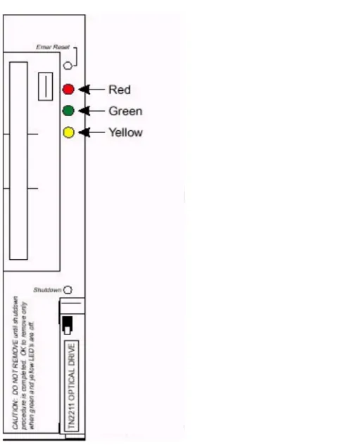
■ The TN2211 Optical Drive is a direct replacement for the TN1656 Tape
Drive, and offers the following:
■ The TN2211 provides removable storage for software upgrades, translation
■ The TN2211 Optical Drive resolves several problems related to the tape
drive such as availability, cost, performance, reliability, and storage capacity.
■ The TN2211 is designed to be less expensive and more reliable than the
TN1656.
■ Installation and Upgrade procedures for the TN2211 optical drive are
nearly the same as for the TN1656 tape drive.
■ The tape commands are replaced by removable-media commands.
— test tape becomes test removable-media, or test rem for the shorthand version.
■ An optical drive is faster than a tape drive, but it is not related to call flow.
— A full backup to an optical disk cartridge takes approximately 20 minutes, compared to about 95 minutes for a tape.
Configuration
■ The configuration is a G3r switch (simplex or duplex) with a TN2211 Optical
Drive and a UN332C MSSNET OR a TN1656 Tape Drive and a UN332B MSSNET.
■ All commands using tape are replaced by removable-media.
■ Commands such as test tape, busy tape, release tape, etc. are replaced by
removable-media.
— The commands are test removable-media, busy removable-media, etc. removable-media can be shortened to rem (test rem, busy rem).
■ If a user enters tape instead of removable-media, the error/help message
“tape is no longer valid; use removable-media” is displayed on the SAT.
■ All instances of tape on output displays are replaced with removable-media
or R-MEDIA as appropriate.
■ Both the tape drive and optical drive are supported by R8 software.
■ G3r switches running R8 software are shipped with the TN2211 Optical
Drive and the UN332C MSSNET
— New switches are shipped with the TN1656 Tape Drive and hardware
■ The UN332C MSSNET must be used with the TN2211 Optical Drive.
NOTE:
UN332C MSSNET is backward-compatible with the UN332B. UN332C will work with a tape drive.
Serviceability
■ A (remote) maintenance user can identify between the two drive types by
using the list config command to determine the TN code.
■ The tape commands are replaced with removable-media commands (rem
for short).
■ A user can verify the correct suffix of the UN332C by reading the circuit
pack label or reading the output from the list configuration control command.
Upgrades
■ Typically, a defective tape drive will be replaced with another tape drive for
existing systems.
■ Customers are not required to upgrade the tape drive to an optical drive for
bugfix.
■ For “purchased” upgrades to R8, the customer will are required to upgrade
■ The procedure to both upgrade from pre-R8 to R8 and to change from a
TN1656 to a TN2211 at the same time is not supported.
■ Services must upgrade the hardware first (TN1656 to a TN2211 and a
UN332B to a UN332C), then upgrade to the R8 software.
— The hardware must be upgraded prior to the software.
■ This will take advantage of the faster optical drive technology
for some of the upgrade steps.
■ This does not require that the new software be shipped on
two different media forms (tape and optical disk cartridge).
■ Replacement of the tape drive with the optical drive does not impact the
Maintenance
NOTE:
Refer to Definity ECS Release 8.2 Upgrades and Additions for R8r, 555-233-115, Issue 1.
■ A TN2211 is maintained in software as if it were a TN1656.
■ After inserting an optical disk cartridge, the access lamp of the drive
should be on for a few seconds, then should turn off.
— Access lamp blinking afterwards typically means a cartridge should be reinserted.
Maintenance Object appears as “R-MEDIA”
■ The Maintenance Object appears as R-MEDIA for either the TN1656 or the
TN2211.
■ This Maintenance Object is used in the output of commands such as
display alarms, display errors, test removable-media, etc., and functions as follows:
— If an error or alarm log contains an entry for TAPE, the description changes to R-MEDIA after the software has been upgraded to R8.
■ The list config command output describes the TN1656 and the TN2211 as
R-MEDIA DRIVE.
■ Both the tape and optical drives are now generically described as
R-MEDIA DRIVE.
— The only way to differentiate between the two drives in R8 is to look at the TN code via the list config command.
No limit on the number of accesses
■ The software is not limited the number of accesses of an optical disk
cartridge.
NOTE:
Important! The TN2211 Optical Drive does NOT require cleaning.
Any attempt to clean the optical drive will damage it.
■ The LMM will display TAPE on boot-up on the SAT, even if an optical drive
and optical disk cartridge are present.
■ In duplicated systems, either carrier may have an optical drive or a tape
drive, since software supports both.
■ The drives can be mixed between carriers (one carrier has a TN1656, the
U.S. Analog Trunk & Line Circuit Pack TN797
Description
This circuit pack is the combination 8-port Analog Trunk and Line Circuit Pack, TN797, for the US, Canada, and like countries. This provides the user with the capability to administer any of the 8 ports of this analog circuit pack as a:
■ Central Office trunk, either loop start or ground start,
■ CAMA E911 trunk,
■ Direct Inward Dialing trunk, either wink start or immediate start; or
■ An analog line, on or off-premises, with or without LED message waiting
indication.
One way of visualizing the capabilities of this circuit pack is to think that when a port is administered as a CO trunk, its capabilities will be similar to those of a port of the analog CO trunk TN747B (or the TN429D used for CAMA/E911); if the port is administered as a DID trunk, its capabilities will be similar to those of the DID trunk TN753B, and if administered as a line circuit, its capabilities will be similar to those of the analog line TN746B.
Note that the TN797 circuit pack does not support ICLID on the analog trunk to the CO, nor Caller ID on the line side to a terminal. Additional capabilities, including additional international features, are being planned for a future release of this circuit pack.
One interesting application of this circuit pack is to provide Emergency Transfer capabilities to a system which has only DS1 connectivity to the central office, or to one that has only digital terminals. This circuit pack will permit analog connectivity to the central office from analog terminals using only one port slot.
There are no changes required in Call Processing for this circuit pack.
The TN797 circuit pack supports all analog terminals supported by the similar analog circuit packs mentioned above. However, neon lamp message waiting indication is not supported by this circuit pack.
TN2313 DS1 Interface (US (24-Channel) or
International (32-Channel))
The TN2313 DS1 interface can be configured for domestic (24-channel, 1.544 Mbps) or international (32-channel, 2.048 Mbps) use. The TN2313 can supply two 8-Khz reference signals to the switch backplane for optional use by the tone/clock board in synchronizing the system clock to the received line clock.
24 Port Analog Line with Caller ID: TN793B
& TN2793B
The TN793/TN793B is a dual coded, analog line 24-port, that performs all the functions of the TN746B, 16-port analog line circuit pack. Each port supports 1 voice terminal, such as 500 (rotary dial) and 2500 terminals (DTMF dial).
The TN793/TN793B supports on-premises (in-building) wiring with either touch-tone or rotary dialing and with or without the LED and neon Message Waiting Indicators. The TN793/TN793B supports off-premises wiring (out-of-building only with certified protection equipment) with either DTMF or rotary dialing, but LED or neon message waiting indicators are not supported off -premises.
The TN793/TN793B, along with a TN755B neon power unit per carrier or per single-carrier cabinet, supports voice terminals equipped with neon message waiting indicators (on-premises use only). The TN793/TN793B supports 3 ringer loads, only 1 voice terminal can have an LED or neon message waiting indicator. The TN793/TN793B allows a maximum of 12 simultaneous ports ringing.
The TN793/TN793B supports A-Law and µ-law companding and administrable timers. The TN793 supports queue warning level lights associated with the DDC and UCD features, recorded announcements associated with the Intercept Treatment feature, and PagePac paging system for the Loudspeaker Paging feature. Additional support is provided for external alerting devices associated with the TAAS feature, neon message waiting
indicators, and modems The TN793/TN793B also supports secondary lightning protection.
The TN793B is compatible with the terminal configurations shown in the table below.
Table 1. Terminals and wiring configurations supported by the TN793
Terminal Wire Size Maximum Range
General Telephony Enhancements -
Global
Coverage of Calls Redirected Off-Net (CCRON)
Release 8 Enhancements
■ Remote SAC Activation/Deactivation Call Processing
■ Threshold Activated CF Timer Call Processing
■ Coverage After Forward (per station) Call Processing
■ ISDN Renewal(long term)
■ Maintain SBA at Principal Call Processing
Remote Send All Calls(SAC) Activation/
Deactivation
■ The Remote Send All Calls Activation/Deactivation feature allows a remote
user to activate or deactivate send all calls.
Remote SAC Activation/Deactivation
■ New Feature Access Codes■ Added to the Feature Access Codes (FAC) form.
— These new feature access codes, followed by the user’s extension, “#,” associated Station Security Code (SSC) and “#,” are used to activate/deactivate Send All Calls (SAC) for the specified extension from any on-site extension or remotely (offnet).
— Activating/Deactivating SAC Via The Remote SAC Feature Access Code Or Existing Method Activating or deactivating SAC via either the Remote SAC feature access codes or existing SAC button or feature access codes have the same effect.
— SAC may be activated by using a local SAC FAC, SAC feature button, or by activating Remote SAC.
Remote SAC Activation/Deactivation Form
■ Added New “Remote Send All Calls Activation:” and “Deactivation:” Fields
on the FEATURE ACCESS CODE (FAC) Form
— FACs allow a remote user to activate or deactivate the Send All Calls feature.
— Feature access codes may be 1 to 4 digits; * and # may be used as the first digit only. The defaults are blank.
‘#’ as Abbreviation for Extension of Currently
Active Appearance
■ For either of the new feature access codes, a ‘#’ dialed directly after the
feature access code will signify that the extension of the appearance being dialed from is the extension being administered, and the extension need not be dialed; i.e., the initial ‘#’ is followed by the Station Security Code, ‘#’.
Remote User
■ Access this feature by dialing the telecommuting access extension
telephone number directly or by being transferred to it.
— Alternatively, the remote user can dial the remote access extension.
■ On receipt of system dial tone the user would enter the appropriate FAC
(either activate or deactivate SAC). Feature Access Code (FAC) Form (page 3 of x)
change feature-access-codes Page 3 of X
FEATURE ACCESS CODE (FAC)
Program Access Code: ____ Refresh Terminal Parameters Access Code: ____
Remote Send All Calls Activation: ____ Deactivation: ____ Send All Calls Activation: ____ Deactivation: ____ Station Security Code Change Access Code: ____
Terminal Dial-up Test Access Code: ____
Terminal Translation Initialization Merge Code: ____ Separation Code: ____ Transfer to AUDIX Access Code: ____
Trunk Answer Any Station Access Code: ____
User Control Restrict Activation: ____ Deactivation: ____ Voice Coverage Message Retrieval Access Code: ____
■ The user then dials the station extension number, followed by a “#” and
station security code (SSC), followed by a “#.”
Local User
■ The Remote SAC Activation/Deactivation feature can also be activated by
a local user from any local extension.
■ The local user would access this feature on receipt of dial tone by entering
the appropriate FAC (either activate or deactivate SAC) and receive recall dial tone.
■ The user then dials the station extension number, followed by a “#” and
station security code, followed by a “#.”
■ If the user is dialing from the extension which is to be administered, the
user may enter just the ‘#’ followed by the SSC, followed by “#,” this will signify to the system that the extension number of the appearance being dialed from is the extension number being administered.
■ Then either confirmation or intercept tone is returned if any of the following
conditions exist:
— The extension number entered is invalid (logged as an invalid attempt).
— The extension number is not accessible from the user’s partition.
— The SSC is invalid for the extension entered (logged as an invalid attempt).
— Interdigit time out has occurred.
■ If activation/deactivation is successful, then confirmation tone is returned
and SAC is either activated or deactivated at this point.
ISDN Renewal (Interworking Assumption)
When CCRON calls are extended over ISDN facilities, two scenarios are possible.
1. ISDN end-to-end facilities are established
Or
2. ISDN end-to-end facilities are not available; a portion of the connection is not ISDN and ISDN facilities interworking is required for some link between endpoints.
■ ISDN end-to-end was assumed for a period of time, after which
Off-Net Coverage Points
■ Any point in a principal’s coverage path can be administered as an off-net
destination.
NOTE:
Time-of-Day Coverage feature increases the number of coverage points from 3 to 6.
Increase Number of Remote Coverage Points
■ Number of Remote Coverage Points available (on all platforms) increased
from 225 to 999.
Increase Number of Coverage Paths
■ Number of coverage paths increased from 600 to 999 on the small mips
and from to 7500 to 9999 on the large mips.
New System Parameters--Call Coverage / Call Forwarding Form, Page 1
change system-parameters coverage-forwarding Page 1 of 2 SYSTEM PARAMETERS -- CALL COVERAGE / CALL FORWARDING
CALL COVERAGE/FORWARDING PARAMETERS
Local Cvg Subsequent Redirection/CFWD No Ans Interval (rings): _ Off-Net Cvg Subsequent Redirection/CFWD No Ans Interval (rings): _ Coverage - Caller Response Interval (seconds): _ Threshold for Blocking Off-Net Redirection of Incoming Trunks Calls: 1
COVERAGE
Keep Held SBA at Coverage Point? _ External Coverage Treatment for Transferred Incoming Calls? _ Immediate Redirection on Receipt of PROGRESS Inband Information? _ Maintain SBA At Principal? _ QSIG VALU Coverage Overrides QSIG Diversion with Rerouting? _ Station Hunt Before Coverage? n
FORWARDING
Call Forward Override? _ Coverage After Forwarding? _
New System Parameters--Call Coverage / Call Forwarding Form, Page 2 CCRON Enabled
change system-parameters coverage-forwarding Page 2 of 2 SYSTEM PARAMETERS -- CALL COVERAGE / CALL FORWARDING
COVERAGE OF CALLS REDIRECTED OFF-NET (CCRON)
Threshold Activated Call Forward Timer
■ Activates “Threshold for Blocking Off-Net Redirection of Incoming Trunk
Calls” field for Release 8.
■ Field has a range of 1-7 and “n”.
— “n” will mean that call processing never activates the Call Forward timer
■ An infinite number of calls to a principal may be redirected
off-net.
— The default is 1, which provides the current operation.
— When a customer is upgraded from a release prior to R8, this field is set to 1.
■ All incoming trunk calls to a particular station are blocked from redirecting
offnet during the call forward timer interval.
■ The R8.1 user can change this value.
Coverage After Forward (Station Option)
■ Adds a new field entitled “Coverage After Forwarding (station specific)?” to
page 2 of the Station form for all stations.
■ The field may contain any of three different values:
— y - indicates, that for this station, coverage treatment should be applied after forwarding, regardless of the value of the “Coverage After Forwarding?” field on the SYSTEM PARAMETERS - CALL COVERAGE / CALL FORWARDING form
— n - indicates, that for this station, coverage treatment should not be applied after forwarding., regardless of the value of the “Coverage After Forwarding?” field on the SYSTEM PARAMETERS - CALL COVERAGE / CALL FORWARDING form.
— default - indicates, that for this station, use the value of the
“Coverage After Forwarding?” field on the SYSTEM PARAMETERS - CALL COVERAGE / CALL FORWARDING form.
New System Parameters--Call Coverage / Call Forwarding Form, Page 2 CCRON Disabled
change system-parameters coverage-forwarding Page 2 of 2 SYSTEM PARAMETERS -- CALL COVERAGE / CALL FORWARDING
COVERAGE OF CALLS REDIRECTED OFF-NET (CCRON)
NOTE:
Application of coverage treatment does not guarantee that the call will definitely redirect to a coverage point, since the coverage criteria as applied at the forwarded-to destination may not be satisfied.
■ When a DEFINITY® system with CCRON activated is upgraded to R8, the
value “s” (for ‘system’) set in the “Coverage After Forwarding ?” field on the Station form for all stations
■ When a customer is upgraded from a release prior to R8, this field is set to
“s” for all stations, indicating that call processing uses the value on the Coverage After Forwarding field on the SYSTEM PARAMETERS--CALL COVERAGE / CALL FORWARDING form.
■ To override the system-wide parameter for a given station, the system
administrator must set the field on the Station form.
Maintain SBA at Principal
■ Allows customers to prevent the appropriation of a call appearance button
on the principal’s phone by the simulated bridge appearance by a coverage call.
— The ability to take phone calls may be more important than the capability of the principal to retrieve calls that have already redirected to coverage.
Station Form (Page 2 of X)
add station 1014 Page 2 of X
STATION
FEATURE OPTIONS
LWC Reception? msa-spe Auto Select Any Idle Appearance? n
LWC Activation? y Coverage Msg Retrieval? y
LWC Log External Calls? n Auto Answer: none
CDR Privacy? n Data Restriction? n
Redirect Notification? y Idle Appearance Preference? n
Per Button Ring Control? n
Bridged Call Alerting? n Restrict Last Appearance? y
Active Station Ringing: single
H.320 Conversion? n
Per Station CPN - Send Calling Number? _ Special Character for Restricted Number? n
MWI Served User Type: ______ Display Client Redirection? n
AUDIX Name: Select Last Used Appearance? n
Messaging Server Name: ______ Coverage After Forwarding? _
Option to Dispense with Call Classifier On
Coverage Call
■ Established a new field, “Maintain SBA At Principal?”
■ This is a y/n field.
■ The default is y, which maintains current operation.
■ When a customer is upgraded from a release prior to R8, this field is set to
y.
13-Digit Authorization Codes
■ The system now supports authorization codes from a minimum of 4 digits
to a maximum of 13 digits in length.
— The number of authorization codes allowed (90,000 in a G3r, 5,000 in a G3i) (not changed).
■ The user may have to dial up to 13 digits to enter an authorization code.
■ The use of the authorization code information for ARS, AAR, incoming
trunk authorization, remote access, or any other feature that may require the collection of an authorization code has not changed.
■ If a standard CDR format is used and there are more than 7 digits in an
authorization code, the authorization code is truncated to the high 7 digits to fit the format.
■ The customized format supports 13-digit authorization codes, and is
encouraged for those with larger authorization codes.
Feature Administration
■ Feature Administration allows the length of the authorization code assigned
on the system - parameters features form to be from 4 to 13 digits.
■ The security violations status form has changed to allow 13-digit
authorization codes.
■ The Authorization Code form shows 4 columns of 16 authorization codes
Call Detail Recording (CDR) Formatting
NOTE:
CDR formats are “standards” therefore no attempt was made to modify them to fit larger authorization codes.
A customized CDR format handles 13-digit authorization codes and allows any format to be created.
■ The form for translating authorization codes has changed to fit the new
maximum length. OLD SCREEN
monitor security-violations authorization-code
SECURITY VIOLATIONS STATUS
Date: 17:51 MON SEP 28 1999 AUTHORIZATION CODE VIOLATIONS
Date Time Originator Auth-Cd TG No Mbr Bar-Cd Ext CLI/ANI 09/28 17:19 Trunk 9639632 1 1
09/28 17:10 Trunk 8998989 1 1
NEW SCREEN
SECURITY VIOLATIONS STATUS
Date: 17:51 MON SEP 28 1999 AUTHORIZATION CODE VIOLATIONS
Date Time Originator Auth-Cd TG/Mbr Bar-Cd Ext CLI/ANI 09/28 17:19 Trunk 9639632123456 1/ 1
09/28 17:10 Trunk 8998989123456 1/ 1
list authorization-code
LIST AUTHORIZATION CODES REPORT
Authorization Code Class of Restriction(COR) 0000000000000 0
— The new form displays a maximum of 48 codes (3 columns), leaving only 1 column for adding more codes.
— To enter more codes, execute change authorization - code 9999999.... to show a blank screen, allowing 64 codes to be submitted at one time rather than the original 96.
■ If using both authorization codes and account codes, be aware that there is
a problem with phone calls that involve more than 36 digits.
— The length of the account code and authorization code should not have more than 36 digits.
As an example:
■ ars access code = 1 digit
■ phone number = 15 digits
■ account code access code = 3 digits
■ This leaves a total of 17 digits for the total of authorization
and account code lengths. Original screen
change authorization-code 1111111 Page 1 of 1 Authorization Code - COR Mapping
NOTE: 96 codes administered. Use ’list’ to display all codes
AC COR AC COR AC COR AC COR AC COR AC COR
1111111 1 2222222 2 3333333 3 4444444 4 5555555 5 6666666 6 1111112 1 2222223 2 3333334 3 4444445 4 5555556 5 6666667 6 1111113 1 2222224 2 3333335 3 4444446 4 5555557 5 6666668 6 . (12 more rows)
. .
1111125 1 2222236 2 3333347 3 4444458 4 5555569 5 6666680 6
New screen
change authorization-code 1111111111111 Page 1 of 1 Authorization Code - COR Mapping
NOTE: 64 codes administered. Use ’list’ to display all codes
AC COR AC COR AC COR AC COR
1111111111111 1 2222222222222 2 3333333333333 3 4444444444444 4 1111111111112 1 2222222222223 2 3333333333334 3 4444444444445 4 1111111111113 1 2222222222224 2 3333333333335 3 4444444444446 4 (12 more rows)
. .
Auto Exclusion
■ When Privacy - Manual Exclusion is activated, all other users with
appearances of an extension are prevented from bridging onto the active call.
— If the Exclusion button is pressed while other users are bridged onto the call, the other users are dropped from the call.
— The only way to activate Exclusion is by pressing the Exclusion button on a per-call basis.
■ Exclusion is deactivated when the Exclusion button is pressed a second
time, or when the call is terminated.
■ Under R8 with Automatic Exclusion active, the Manual Exclusion feature
can now be automatically activated on a COS basis.
■ If a user is assigned a COS which has the Automatic Exclusion option set
to y, then Exclusion will automatically be activated when the user goes off hook on a station which has an Exclusion button assigned.
■ Manual Exclusion can be activated while active on a call and it can be
activated before dialing.
■ Manual Exclusion still cannot be activated while the user is idle (onhook).
■ Under R8 with Automatic Exclusion active, a held exclusion call can be
unheld by any station with a bridged appearance of the appearance that put the call on hold.
■ Automatic Exclusion will NOT be automatically activated when the principal
(or a bridged appearance of the principal) bridges onto a call that has been answered by a coverage point.
COS screen
change cos Page 1 of 1 CLASS OF SERVICE
0 1 2 3 4 5 6 7 8 9 10 11 12 13 14 15
Auto Callback n y y n y n y n y n y n y n y n
Call Fwd-All Calls n y n y y n n y y n n y y n n y
Data Privacy n y n n n y y y y n n n n y y y
Priority Calling n y n n n n n n n y y y y y y y
Console Permissions n n n n n n n n n n n n n n n n
Off-hook Alert n n n n n n n n n n n n n n n n
Client Room n n n n n n n n n n n n n n n n
Restrict Call Fwd-Off Net n y y y y y y y y y y y y y y y
Call Forward Busy/DA n n n n n n n n n n n n n n n n
Personal Station Access n n n n n n n n n n n n n n n n
Extended Forwarding All n n n n n n n n n n n n n n n n
Extended Forwarding B/DA n n n n n n n n n n n n n n n n
Trk-to-Trk Restriction Override n n n n n n n n n n n n n n n n
QSIG Call Offer Originations n n n n n n n n n n n n n n n n
■ Allows a user to activate automatically Exclusion when they go off hook on
a station that has an assigned EXCLUSION button. If set to n, allows a user manual exclusion when they press the EXCLUSION button before dialing or during a call. Appears when, on the Feature-Related System Parameters screen, the Automatic Exclusion by COS field is y.
■ Automatic Exclusion by COS
Activates automatic exclusion automatically by class of service when a user goes off hook on a station with an assigned EXCLUSION button. This works only for stations on the local switch.
■ Automatic Exclusion Coverage/Hold
Appears when Automatic Exclusion by COS field is y.
■ Automatic Exclusion with Whisper Page
Appears when Automatic Exclusion by COS field is y. Feature-Related System Parameters screen - Page 10
change system-parameters features Page 10 of 10
FEATURE-RELATED SYSTEM PARAMETERS
AUTOMATIC EXCLUSION PARAMETERS
Automatic Exclusion by COS? y Automatic Exclusion Coverage/Hold? y Automatic Exclusion with Whisper Page? y Recall Rotary Digit: 2
Valid entries Usage
y Enables automatic exclusion by a class of service.
n Exclusion operates normally.
Valid entries Usage
y The principal can bridge onto the call by pressing the appropriate bridged appearance button. And, if the coverage point places the exclusion call on hold, the principal can retrieve the call.
n If a coverage point has answered a call and there is active
exclusion on the call, the principal cannot bridge onto the call. And, if the coverage point places the exclusion call on hold, the principal cannot retrieve the call.
Valid entries Usage
y The whisper page goes through to an excluded call.
n The whisper page is denied when a station attempts to whisper
■ Recall Rotary Digit
This establishes the digit to use for rotary phones to receive recall dial tone. Dialing this digit simulates switch hook flash so that users of rotary phones can use features such as conference and transfer. The phone must also be administered to use the recall rotary digit.
64 Bridged Call Appearances
■ DEFINITY® system bridged appearance limit of 26 expanded to 64.
— Bridged appearance feature button for a given extension increased to 63, reserving one appearance for the primary set.
■ There are limits on the number of sets per system that can be administered
for more than 26 bridged appearances per set.
— R8 csi and si can have up to 50 such sets, while R8r can have up to 250 such sets.
Circular Station Hunting
■ Provides a new method of administering a hunt group.
■ A new group type, circ (for circular)added to the list of available group types
entered on the Hunt Group form.
— When administering a circular station hunt group, the order in which the extensions for those stations participating in the hunt group are administered is the order in which calls will be directed.
— System must keep track of the last extension in the hunt group, to which a call was connected, such that when the next incoming call arrives, the system can determine the next idle extension in the circular hunt group.
— Extensions in the hunt group that are busy are skipped in the algorithm, and the next idle extension within the hunt group is selected regardless of past call history.
■ The caller hears a busy tone when all extensions in the hunt group are
busy.
— The capability exists to have a call go to coverage or to the attendant if there are no idle stations available in the hunt group.
Valid entries Usage
Group Call Pick-up
■ Work groups in Japan use this feature.
■ Allows users to dial a FAC and then a pickup group number, in order to
answer a call pickup call from a different call pickup group.
Long Hold Recall – Warning
■ When a call stays on hold past an administered time, this feature will give
visual or audible warnings to the set that put the call on hold, similar to the warning given to attendants when calls stay in queue too long.
Reset Shift Call
■ When a call is made to a busy station, special dial tone is heard (called
second dial tone by Japanese PBX manufacturers).
■ After special dial tone, a single digit may be entered which replaces the last
digit of the originally dialed extension, and the call is offered to the new station.
■ If call coverage is supplied for the dialed extension, the call goes to
coverage as normal.
■ If the coverage extension is busy, the special dial tone is heard and a single
digit may be entered.
■ Active for station to station calls, but not for incoming calls nor outgoing
calls.
■ Operation for transfer and conference is similar: if the third party is busy,
special dial tone is heard and an opportunity is provided for a last digit re-entry as on a normal call.
Station Self Display
■ When a station user goes offhook, the station set will display the extension
number of the set itself.
■ Once the user starts to dial, the dialed number is displayed.
■ People in small work groups in Japan use this feature as they move from
desk to desk while working.
Special Dial Tone [China]
■ Adds the ability to play a special dial tone whenever an analog set would
■ Examples of such features or conditions include:
— Features that can be activated and deactivated via a FAC from the station, and cause some re-routing of calls to that station
— Features that can be activated and deactivated via a FAC from the station and invoke some restriction of calls from the station
■ The special dial tone of 450 Hz, on 400ms, off 50ms, repeating, at -10 +/- 3
dBm0.
■ Tone is administered via the country code, and via the current tone
administration.
6200 Analog Native Support
Description
■ The 6200 Analog Native Support feature provides the user with the
capability to administer the 6200 family of analog terminals directly in DEFINITY® ECS rather than aliasing them as some other existing terminal.
■ The terminal type, CallrID, added to permit the aliasing of various terminals
and adjuncts for Caller ID purposes.
■ When CallrID (one word limited to seven characters) is designated, this
permits the aliasing of analog terminals with Caller ID capabilities, or analog terminals with Caller ID boxes, or adjuncts, capable of displaying calling party information via Bellcore (US, Bahrain V.23) or NTT (Japan) standards.
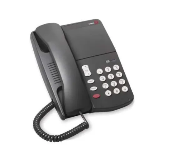
■ Analog terminals are 6210, 6218, and 6220.
Upgrades
■ To function with the Caller ID feature, TN793B or TN2793B is required with
terminals administered or aliased as CallrID.
Administration
Screen for 6200 Terminals
■ The administration screen shows the Page 1 of the STATION
administration form where, as an example, station 1000 has been administered as a 6210 terminal.
■ HELP values for the “Type” field will include 6210, 6218 and 6220.
Caller ID Terminals
■ A Caller ID terminal is required, in addition to the TN793B or TN2793B
circuit pack and Software Release 8 (or later), to implement the Caller ID feature.
■ Provides an expedient manner for administering non-Lucent Caller ID
terminals when a customer requires the Caller ID feature.
■ New fields on the STATION form:
— Display Caller ID?
— Caller ID Message Waiting Indication? Station Form
add station next Page 1 of 3 STATION
Extension: 1000 Lock Messages? n
Type: 6210 Security Code: TN: 1 Port: Coverage Path 1: COR: 1 Name: Coverage Path 2: COS: 1 Hunt-to Station: Tests? y
STATION OPTIONS
Off Premises Station? n Message Waiting Indicator: led Message Lamp Ext: 1000
STATION Form
add station next Page 1 of 3
STATION
Extension: 1000 Lock Messages? n
Type: CallrID Security Code: TN: 1 Port: Coverage Path 1: COR: 1 Name: Coverage Path 2: COS: 1 Hunt-to Station: Tests? y
STATION OPTIONS
■ HELP values for the Type field include CallrID.
NOTE:
CallrID is one word, limited to seven characters by Type field constraints.
■ The fields Display Caller ID? y and Caller ID Message Waiting Indication? n
appear in this form only when CallrID is chosen as the terminal Type.
■ When Display Caller ID field is set to y (yes), calling party information is
transmitted to the Caller ID terminal via Bellcore (US, Bahrain V.23) or NTT (Japan) protocol.
— When not desired, field should be set to n.
■ Caller ID Message Waiting Indication? n: When set to n (no), FSK
message waiting indication is not transmitted to the Caller ID terminal.
— If FSK message waiting indication is transmitted to a Caller ID terminal, this field should be set to y.
— Sending FSK message waiting indication to a Caller ID terminal is independent of the administration of the Message Waiting Indicator field.
■ The choices for these two fields should be selected according
to the capabilities of the Caller ID terminal used.
Description of the terminals
6210
■ 6210 is a Lucent set with handset volume control, ringer volume control,
timed switch-hook disconnect, tone dialing (only), Flash, Set Redial, Set Hold, Data Jack (same T&R pair), and DEFINITY® system LED MWI.
6218
■ 6218 is a Lucent set that is the same as the 6220, but without
Speakerphone and without Mute.
6220
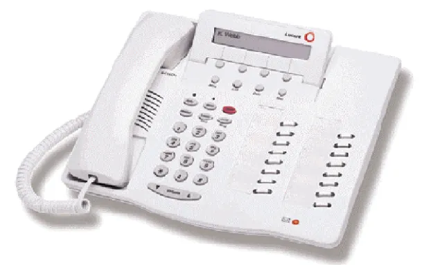
■ 6220 is a Lucent set with 6210 features plus Speakerphone, Mute,
Repertory Dialing, Repertory Keylock, Set Personalized Ring, System Hold CallrID, and Caller ID analog terminals (analog terminals with Caller ID boxes, or adjuncts) that support Caller ID according to Bellcore, Bellcore V.23, or NTT standards.
■ MWI is supported via FSK (Bellcore standard). MWI is also optionally
supported via DEFINITY® system LED voltage method or via neon lamp.
■ TeleMatrix and Teledex Caller ID terminals use a neon lamp MWI in
NOTE:
Caller ID feature requires the TN793B or TN2793B circuit pack.
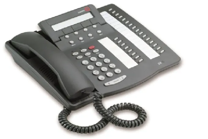
Figure 3. 6220 Analog Telephone
Description of the terminals(continued)
■ The 6200 family of analog terminals requires DEFINITY® ECS R8
software.
■ If R8.1 is used as a bugfix, access to the CallrID terminal type is blocked.
— Access is not blocked for the 6200 family of terminals.
■ 6200 Analog Native Support is available and supported in both Offer
Category A and Offer Category B.
■ 6200 family is compatible with existing DEFINITY® system analog line
circuit packs.
— Can be used where the 8110 terminal is used.
Caller ID terminals
■ TN793B/TN2793B circuit pack supports the following Caller ID terminals:
— TeleMatrix 2802 CID Guest Room Telephone
— Teledex Millennium 2505C and 2510C
— Commercial sets with Caller ID capabilities that comply with the protocols supported by the Caller ID
NOTE:
Many Caller ID protocols specify FSK signaling for MWI.
6400 Tip/Ring (Data Module Features)
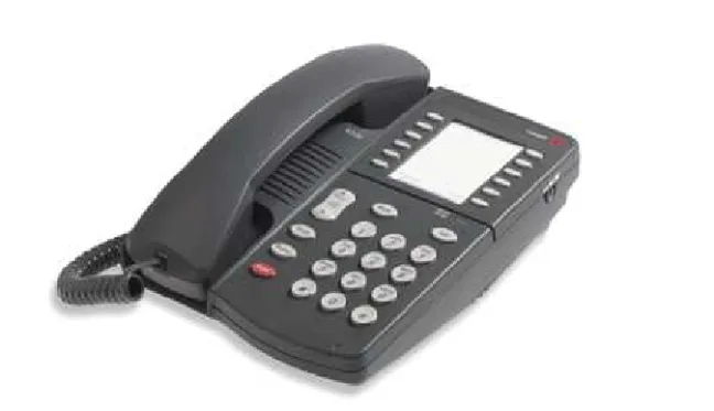
■ The 6400 Tip/Ring feature supports the operation of an analog adjunct
operating independently on an I2 channel with its own extension for 64xx DCP telephones.
■ Allows the operation of an analog adjunct to be independent of the digital
telephone’s extension for the use of fax machines or modems without compromising the user’s voice extension.
— 6416D+
— 6424D+ DCP
NOTE:
When set for I2 operation, the module transmits an
S2-channel button press message for button 01h of group 00h whenever it detects an analog switch hook flash.
Figure 5. 6424D+ DCP Terminal
Administration
The 6416D+ and the 6424D+ terminals are administered with a data option field for an analog adjunct.
■ Administer as a data module field on add station form.
■ An option on the add station form allows users to administer their own
particular extension.
— Previously, what is now the data option field, was the data module field for all of the 6400 terminals.
■ DEFINITY® system 8.1 provides the following form only if the set is a
6416D+ or 6424D+ and Expansion Module = y on Page 1.
■ DEFINITY® system 8.1 provides the following form if the set is a 6416D+ or
6424D+ and data option is equal to analog Station Form page 1 used for 6416D+ and 6424D+ terminals only
Page1 of X STATION
Extension: 1003 Lock Messages? n BCC: 0 Type: 6424D+ Security Code: ____ TN: 1_ Port:_______ Coverage Path 1: ____ COR: 1_ Name: ________________________ Coverage Path 2: ____ COS: 1_ Hunt-to-Station: _______
STATION OPTIONS
Loss Group:
Data Option: analog Personalized Ringing Pattern: 1 Speakerphone: 2-way Message Lamp Ext: 1000 Display Language: english Mute Button Enabled? y Expansion Module? n MM Complex Data Ext: n
Station form used only with 6416d+ or 6424d+ equipped with XM24 expansion module
Page X of X STATION
EXPANSION MODULE BUTTON ASSIGNMENT
NOTE:
DSA is impacted when implementing these new features.
Station Form used only with the 6416D+ or the 6424D+ when Data Option equal to analog
Page 6of 6 STATION
Analog Adjunct
Data Extension: 1003 Name: BCC: 0 COS: 1
COR: 1 ITC: restricted TN: 1
ABBREVIATED DIALING List1:
SPECIAL DIALING OPTION:
ASSIGNED MEMBER (Station with a data extension button for this analog adjunct)
Ext Name 1:
Station Form Page 3 Used For All 6400 Voice Terminals Except the 6402/D
Page 3 of X STATION
SITE DATA
Room: ______________ Headset? n Jack: ____________ Speaker? y Cable: ___________ Mounting: d Floor: ______________ Cord Length: 0
Building: ______________ Set Color: __________
ABBREVIATED DIALING
List 1: ________ List 2: ________ List 3: ________
BUTTON ASSIGNMENTS
Station Form Page 3 Used For 6402/D Voice Terminals Only
Page 3 of X STATION
SITE DATA
Room: ______________ Headset? n Jack: ____________ Speaker? y Cable: ___________ Mounting: d Floor: ______________ Cord Length: 0
Building: ______________ Set Color: __________
ABBREVIATED DIALING
List 1: ________ List 2: ________ List 3: ________
BUTTON ASSIGNMENTS 1: call-appr________ 2: call-appr________
Station Form Page 4 Used For 6402/D Voice Terminals Only
Page 4 of X STATION
Station Form Page 4 Used For 6416D+ Only
Page 4 of X STATION
FEATURE BUTTON ASSIGNMENTS 1: _____________________ 2: _____________________ 3: _____________________ 4: _____________________ 5: _____________________ 6: _____________________ 7: _____________________ 8: _____________________
Station Form Page 4 Used For 6424D+ Only
Page 4 of X STATION
FEATURE BUTTON ASSIGNMENTS
Station Form Page 5 Used for all 6400 Display Sets Other Than the 6402D
Page 5 of X STATION
SOFTKEY BUTTON ASSIGNMENTS 1: ______________________ 2: ______________________ 3: ______________________ 4: ______________________ 5: ______________________ 6: ______________________ 7: ______________________ 8: ______________________ 9: ______________________ 10: ______________________ 11: ______________________ 12: ______________________
Station Form used Only With 6416D+ or 6424D+ Equipped With XM24 Expansion Module
Page X of X STATION
EXPANSION MODULE BUTTON ASSIGNMENT
Tip Fields
6400 Terminal Parameters Form
Page X of X STATION
6400-TYPE TERMINAL PARAMETERS
Default Parameter Set: 1 Customize Parameters? y
OPTIONS
Display Mode: Handset Expander Enabled? Volume:
PRIMARY LEVELS
Voice Transmit (dB): Voice Sidetone (dB): Voice Receive (dB): Touch Tone SideTone (dB): Touch Tone Transmit (dB):
2-WAY BUILT-IN SPEAKER LEVELS:
Voice Transmit (dB): Voice Receive (dB): Touch Tone Transmit (dB):
1-WAY BUILT-IN SPEAKER LEVELS
Voice Receive (dB): Touch Tone SideTone (dB):
Fields, field placements, and valid keywords
6400 8400/ 9400 Differences
6402/D 8403B 6402 has 1 less call appearance.
6408 8410B 6408 has 2 less call appearances and no 2
way-speaker-phone.
6408+ 8405B 6408+ has 3 more call appearances
6408D 8405D 6408D has 3 more call appearances and no
2-way speaker-phone.
6408D+ 8405D+ 6408D+ has 3 more call appearances.
6416D+ 8434D 6416D+ has 18 less call appearances and 3 less
soft-keys
(12 v 15). The 8434 has a 2 x 40 display instead of a 2 x 24 display
6424D+ 8434D 6416D+ has 18 less call appearances and 3 less
soft-keys
Support for 24-button expansion modules
■ The XM24 expansion module is fully functional when administered together
with the 6416D+ and 6424D+ voice terminals.
Abort Transfer
■ The Abort Transfer provides the user with the optional capability to abort a
transfer attempt when pressing a nidle line appearance or going on-hook, putting the previously soft-held call on hard hold.
■ In a Pre Release 8.1 operation, the user might have received an urgent call
that they needed to pick up and then later transfer the urgent call to yet another party.
— The user forgets that the first call is still on soft-hold awaiting transfer and the user instead presses the transfer button to transfer the urgent call to a third party.
— As soon as the user presses the transfer button, the first and second calls are transferred together which is not what the user intended.
— If the user of a DCP, Hybrid, Wireless, or ISDN-BRI terminal presses a non-idle call appearance (or goes on-hook) in the middle of performing a Transfer operation, the Transfer operation is not aborted but is left in an active state.
■ Abort Transfer allows abort the transfer operation whenever he/she
presses a non-idle call appearance in the middle of the transfer operation or when the user hangs-up (assuming that the Transfer Upon Hang-Up feature is not enabled).
■ The original call that was on soft-hold in the transfer-pending mode will be
changed to be on hard-hold so that the original call is not lost.
■ When the user then presses the transfer button, the user will be initiating a
new transfer for the call appearance he/she is currently on.
Abort Conference
■ The Abort Conference enhancement provides the user with the optional
capability to abort a conference attempt when going on-hook, putting the previously soft-held call on hard hold.
■ This allows the user of a DCP, Hybrid, Wireless, or ISDN-BRI terminal to
abort the conference operation whenever they hang-up.
NOTE:
The original call that was on soft-hold in the conference-pending mode will be changed to be on hard-hold so that the original call is not lost.
■ When the user later presses the conference button, the user will be
NOTE:
The Abort Transfer / Abort Conference features are not applicable to Attendant Consoles.
Administration
Enable Abort Transfer Operation and Enable Abort Conference
Operation
■ Enabled/disabled on a per-system basis by the use of 2 new fields on the
system-parameters features form.
■ Automatically disabled on upgrades.
New on the system-parameters features form
■ “Abort Transfer?” and “Abort Conference Upon Hang-Up?” are added to
Page 5 of the form as shown
■ Abort Transfer? Fixed field identifying whether the Abort Transfer feature is
enabled or disabled.
— Help: n(o), y(es)
— Default: n
— Error: invalid entry, press help.
■ Abort Conference Upon Hang-Up? Fixed field identifying whether the Abort
Conference feature is enabled or disabled.
— Help: n(o), y(es)
change system-parameters features Page 5 of 10
FEATURE-RELATED SYSTEM PARAMETERS
Public Network Trunks on Conference Call: 5 Auto Start? n
Conference Parties with Public Network Trunks: 6 Auto Hold? n
Conference Parties without Public Network Trunks: 6 Attendant Tone? y
Night Service Disconnect Timer (seconds): 180 Bridging Tone? n
Short Interdigit Timer (seconds): 3 Conference Tone? n
Unanswered DID Call Timer (seconds): ____ Intrusion Tone? n
Line Intercept Tone Timer (seconds): 30 Special Dial Tone? n Long Hold Recall Timer (seconds): 160
Reset Shift Timer (seconds): 0
Station Call Transfer Recall Timer (seconds): 0 DID Busy Treatment: tone
Allow AAR/ARS Access from DID/DIOD? _
Allow ANI Restriction on AAR/ARS? _ Transfer Upon Hang-Up? n
Abort Conference Upon Hang-Up? n Abort Transfer? n
7405ND Numeric Terminal Display? n 7434ND? n
DISTINCTIVE AUDIBLE ALERTING
Internal: 1 External: 2 Priority: 3
Attendant originated Calls:_ ________
— Default: n
— Error: invalid entry, press help.
Attendant Vectoring
Attendant Call Vectoring is a stand alone feature that is supported on a single switch environment with or without CAS. Attendant Call Vectoring permits unique treatment for each of the attendant-seeking calls according to a number of factors, as defined by the Vector Directory Numbers for each functionality, so as to provide a highly flexible approach for managing incoming calls to an attendant on a DEFINITY switch.
Terminology and Acronyms
Table 2. Terms and Acronyms
Term Meaning
BSR Best Service Routing
CAS Centralized Attendant Service
IAS Inter-PBX Attendant Service
RLT Release Link Trunk
TAAS Trunk Answer Any Station
TN Tenant Number. Tenant numbers are assigned to all endpoints in the system and indicates which tenant partition the endpoint belongs to. If tenant
partitioning is not administered the system has only one “universal” tenant partition and all endpoint TN numbers are defaulted to 1.
Attendant Group Calls
Attendant group calls are calls directed to an attendant group; calls to an individual attendant (via the assigned extension) are not considered attendant group calls. Calls begin as or become attendant group under the following conditions:1
■ Call to Listed Directory Number (LDN)
■ Attendant group in coverage path
■ Attendant control of trunk group access
■ Attendant return calls
■ Attendant serial calls
■ Calls forwarded to attendant group
■ Controlled Restriction
■ Dialed attendant access code
■ Emergency access (dialed FAC or off hook timeout)
■ VIP Wakeup
■ DID/Tie/ISDN intercept treatment
■ DID time-out due to Unanswered DID Call Timer expiry
■ DID busy treatment
■ Call Park time-out
■ Call Transfer time-out
■ Security Violation Notification (SVN)
■ Multifrequency signaling with attendant group as terminating destination
■ CDR buffer full with attendant group as Call Record Handling Option
■ Trunk incoming destination is attendant group
■ Trunk group night service destination is attendant group
■ Hunt group night service destination is attendant group
■ Automatic Circuit Assurance (ACA) referral calls
■ VDN routes to the attendant access code
Attendant group calls terminate to the attendant group associated with a particular party’s tenant number (TN). When tenant partitioning is not administered, the system can have only one “universal” tenant partition and attendant group in which attendants can be members. Any attempt to assign an attendant to an
1. Multimedia data calls can also be sent to an attendant group, but only voice is being supported for R8 attendant vectoring. Data calls were not originally supported for basic vectoring and support is still incomplete. Since there is no need to provide this
attendant group other than 1 is denied. All endpoints in the system are defaulted to TN 1 which by default belongs to attendant group 1. Any attempt to assign TN numbers other than 1 is also denied. So, attendant group calls will always terminate to attendant group 1. For example, station 2000 is assigned TN 1 so when the attendant access code is dialed from station 2000, the call terminates to attendant group 1.
When tenant partitioning is administered, attendants can be assigned to multiple attendant groups and endpoints can be assigned TN numbers for any of the tenant partitions. The TN is associated with an attendant group via the tenant form. So, tenant partitions 1 and 2 can be associated with separate attendant groups or the same attendant group. Attendant group calls still terminate to the attendant group assigned to a party’s TN. For example, station 2000 is assigned TN 1 which is associated with attendant group 1. Station 3000 is assigned TN 2 which is associated with attendant group 2. When the attendant access code is dialed from station 2000, the call terminates to attendant group 1 and when dialed from station 3000, terminates to attendant group 2. This is a flexible method of assigning multiple tenant partitions to be controlled by one attendant group or assigning each tenant partition a separate attendant group.
Call Vectoring
Call vectoring provides a highly flexible approach to managing calls. It consists of three basic components:
1. A Vector Directory Number (VDN)
2. Vectors
3. Vector commands
The VDN is an extensi