ISSN: 2089-3272, DOI: 10.11591/ijeei.v7i3.1066 432
Comparison of Transient Stability Response for MMPS using
UPFC with PI and Fuzzy Logic Controller
Rashid H. AL-Rubayi 1, Luay G. Ibrahim 21,2Department of Electrical Engineering, University of Technology, Baghdad, Iraq
Article Info ABSTRACT
Article historys:
Received Feb 24, 2019 Revised May 1, 2019 Accepted Sep 13, 2019
The increasing pressure on the power system increases the complexity that is becoming a concern for the stability of the power system and mainly for transitory stability. To operate the system in the event of faults, Flexible AC Transmission System (FACTS) devices are used that provide opportunities to control power and vibrations damping. This paper deals with the two control strategies of the Unified Power Flow Controller (UPFC) to damping the system oscillations stability. The stability of the Multi-Machine Power System (MMPS) was analysed with the presence of UPFC. The first strategy is the traditional PI controller (PI-C) with UPFC, and the second strategy is the proposed Fuzzy Logic controller (FL-C) proposed for UPFC device along with PI controller. The MATLAB R2014a was used in all simulations. Based on the results, FL-C for UPFC device along with the PI controller has proven its superiority by has enhanced response to the system, thus minimized in the transitions overshoot and undershoot, and has lower ripple compared to traditional PI-C, both with and without UPFC.
Keywords: FACTS FL-C MMPS PI-C UPFC Transient stability Corresponding Author: Luay G. Ibrahim,
Department of Electrical Engineering, University of Technology,
Baghdad, Iraq.
Email: Luay_g@ yahoo.com
1. INTRODUCTION
Currently, power transmission networks have become narrower due to the increased demand for power, because of many stability problems such as overloading some transmission lines and over-voltage after a disturbance [1, 2]. It is worth mentioning that the current main shut-downs across the world prone to instability and also in advanced and protected systems. The Transient Stability (TS) mentions to the capacity of the power system to preserve synchronization when exposed to acute transient disturbances such as unexpected change of load and faults [3, 4]. The resulting system response involves large oscillations in generator speed and rotor angle. The TS of the complex power system can be enhanced by using Flexible AC Transmission System (FACTS) [5].
In this paper, Unified Power Flow Controller (UPFC) is used as one of the most potent FACTS devices because it has the feature of both series and parallel devices as controlling the flow of active and reactive power and is efficacious in dealing with the turbulences occurring within the electrical network [6-8]. The FACTs can control the network condition quickly. This lets the present network to obtain the usage efficiently and thus evade the necessity for making newlines [9]. The modelling and optimum tuning of different FACTs for dynamic stability enhancement in Multi-Machine Power System (MMPS) was studied in [10].
Presently, FACTS-devices are individually controlled. In any case, the use of modern algorithms and methods has increased power transmission capacity, stability, and reliability of transmission systems. Therefore, the use of appropriate control units will maintain the stability of the electrical system, which will help provide easy and stable electrical energy. [11, 12]. The PI-controller becomes been used in recent years to improve both temporary and fixed performance, as well as to reject disturbances caused by startup events [13-15]. Therefore, this paper suggests a Fuzzy Logic controller (FL-C) along with a PI controller (PI-C) to improve the performance of UPFC in the event of a fault compared to the traditional PI controller with UPFC, especially for the overshoot, undershoot, and settling time.
2. RESEARCH METHOD 2.1 Control of UPFC
UPFC is the commonly versatile member from FACTS devices, by using power electronics to control the flow of power on the power networks. The UPFC implements a mixture of a series controller (SSSC) and shunt controller (STATCOM); these controllers are interconnected over the shared DC bus as presented in Figure 1.
Figure 1. The basic scheme of UPFC
Both of shunt and series converters utilize Voltage Sourced Converter (VSC), which connected to the secondary of the coupled transformer. VSC works to force the commutated power electronic devices (GTO, IGBT or IGCT) to create a voltage from the D.C voltage source. The shared capacitor, which connected to D.C side of the VSC, operates as D.C voltage source [16, 17].
2.1.1 Shunt converter controls
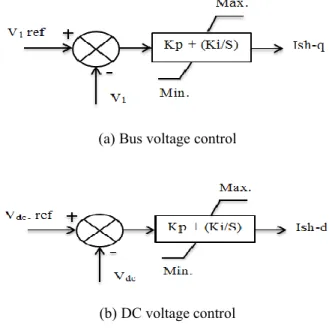
The shunt converter controls the magnitude of the voltage at sending end bus. This converter has two commitments: generating or absorbing active power and to supplying or absorbing reactive power at the dc terminals as requested by the series converter. Controlling the dc voltage accomplishes the real power equilibrium between shunt and series converter as any overabundance or shortage, the real power will stand faced by increasing or decreasing a dc voltage respectively. Based on changing the angle and magnitude of the output voltage of the shunt converter, the reactive and active power flow in the shunt converter is controlled [18, 19].The PI bus voltage regulator and PI dc voltage regulator set the reactive current reference and real current reference respectively as shown in Figure 2. This control scheme is STATCOM control.
(a) Bus voltage control
(b) DC voltage control
Figure 2. Shunt converter current controller
The shunt converter controls the bus voltage by injecting reactive current in quadrature with sending end V1. The magnitude of the shunt voltage is calculated in the following equation:
I
X
V
IJEEI, Vol.7, No. 3, Sept 2019: 432 – 440
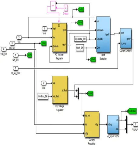
converter and power system. The dynamic blocks of the shunt converter controller for UPFC as shown in Figure 3.
Figure 3. Dynamic blocks of shunt controller for UPFC 2.1.2 Series converter controls
For the series converter, two different control schemes are implementing. The first one is to control the real and the reactive power flow in the transmission line, other control schemes for controlling the flow of the real power in the transmission line and voltage amplitude at receiving end bus. According to the theory for UPFC, the serial converter is the primary of the UPFC; two separate PI controllers are using to control active and reactive power. The flow of real power influenced by changes phase angles. On the other sense, the flow of reactive power directly related to the voltage amplitude.
The outputs of PI-C are constituents d and q of the injected series Vse-d. and Vse-q. sequentially. The
voltage series magnitude is calculated in the following equation:
)
(
)
(
. .P
P
S
Ki
Kp
V
se−q=
+
ref−
(2))
(
)
(
. .Q
Q
S
Ki
Kp
V
se−d=
+
ref−
(3))
(
2 . 2 . . se d se q seV
V
V
=
−+
− (4)Where Vse-q. is series injected voltage in quadrature, Vse-d. is series injected voltage in direct, Kp is
proportional gain, Ki is integral gain, Pref. is reference power, Qerf. is reference reactive power and Vse. is series
injected voltage.
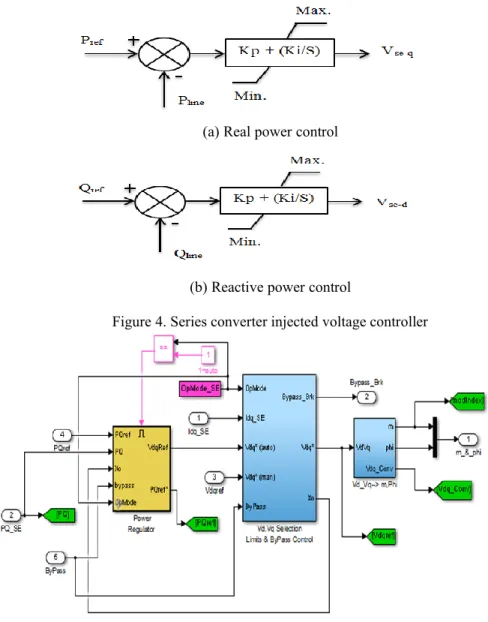
The PI real power regulator and PI reactive power regulator set the reactive voltage reference and real voltage reference respectively as shown in Figure 4. This control scheme is as an SSSC.This control scheme is as an SSSC. The series converter is shown in Figure 5.
(a) Real power control
(b) Reactive power control
Figure 4. Series converter injected voltage controller
Figure 5. Dynamic Blocks of the series controller for UPFC 2.2. Fuzzy Logic Controller
Theory of the fuzzy logic (FL) establish the rules of a non-linear charting. The FL-C rule sets provide a basis for a methodical technique for the application of uncertain and indefinite simulations. It is much closer in spirit to human thinking and natural language than classical logical systems. Now, FL used in all areas of science and industry. The fuzzy control public consists of four units: a fuzzy rule, a fuzzy inference, and fuzzification/defuzzification units [20, 21]. Figure 6 shows the interconnections between units and the controlled process.
IJEEI, Vol.7, No. 3, Sept 2019: 432 – 440
Figure 7 illustrates the Simulink model of the FL-C with a PI Voltage controller for the shunt current controller of the UPFC. Fuzzy logic shunt controller is fed by a difference in power (DP). This gives the suitable shunt current (Iq), which is wanted by the system through a transient period and gives zero output to the steady state.
Figure 7. Fuzzy logic controller with PI-C of shunt converter
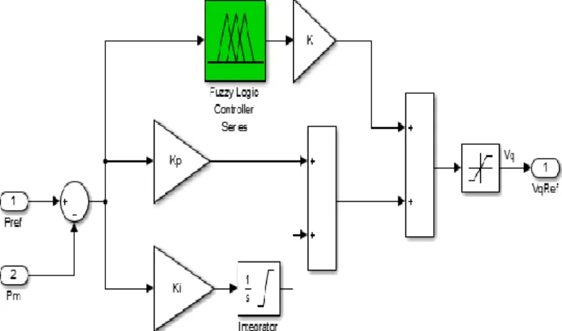
Figure 8 illustrates the modelling Simulink of the FL-C with a PI power flow controller for the series voltage controller of the UPFC. The FL-C is fed by a difference in power. This gives the suitable series injected voltage (Vq), which is wanted by the system through a transient period and gives zero output under steady state.
Figure 8. Fuzzy logic controller with PI power flow controller of the series converter 3. RESULTS AND DISCUSSION
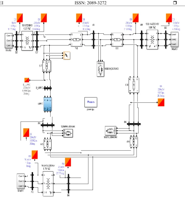
The system of the IEEE 9-buses was designed with all needed components using the MATLAB/Simulink blocks shown in Figure 9 for analysis and system data given in [22]. The base MVA and system frequency are considered to be 100 MVA and 50 Hz, respectively. The generator (Gen.1) is connected to slack at bus 1, whereas Gen.2 and Gen.3 are connected to buses 2 and 3, respectively. The loads A, B, and C are connected to buses 5, 7 and 8 respectively.
The UPFC-device is located in transmission line 4 between buses 5 to 7 in the IEEE 9-bus. This fault is occurred at line 2, near bus7 with the breaker of line 2 at near from bus7 opened for both statuses without and with UPFC installed on line 4 between buses 7 and 5: (t_f =1sec. and t_c=1.14sec.)
Figure 9. Simulink model of the IEEE 9-bus
The Figure 10 and Figure 11 show the rotor angle deviation of 2 and 3 with respect to gen.-1 while Figure gen.-12 and Figure gen.-13 show the rotor speed deviation of gen.-2 and gen.-3 with respect to gen.-gen.-1.
IJEEI, Vol.7, No. 3, Sept 2019: 432 – 440
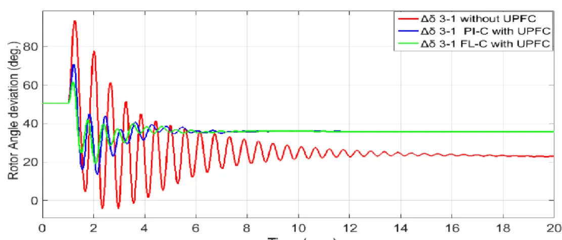
Figure 11. Rotor angle deviation of gen.-3 with respect to gen.-1 for a controller with and without UPFC
Figure 12. Rotor speed deviation of gen.-2 with respect to gen. -1 for a controller with and without UPFC
Figure 13. Rotor speed deviation of gen.-3 with respect to gen.-1 for a controller with and without UPFC These plots show the rotor angle deviation and rotor speed deviation with and without the put of the UPFC in the system. It is apparent from these figures that UPFC with the proposed controller it was verified that the Fuzzy logic controller along with PI controller response presents better results than the system using a PI controller. Besides the overshoot and undershoot already being minimized in the transitions, it has a lower ripple. Table 1 and Table 2 show a comparison between different controllers for rotor angle deviation of gen.-2 and gen.-3 with respect to gen.-1. Table 3 and Table 4 show a comparison between different controllers for rotor speed deviation of gen. - 2 and gen.-3 with respect to gen.-1.
Table 1. Comparison between different controllers for rotor angle deviation of gen.-2 with respect to gen.-1 Strategy type Overshoot (deg.) Undershoot (deg.) Settling time (s)
Without UPFC Unstable Unstable Unstable
PI-C with UPFC 105.7 37.75 11.40
FL-C with UPFC 92.02 51.91 9.825
Table 2. Comparison between different controllers for rotor angle deviation of gen.- 3 with respect to gen.-1 Strategy type Overshoot (deg.) Undershoot (deg.) Settling time (s)
Without UPFC 93.60 4.557 18.56
PI-C with UPFC 70.90 16.50 10.38
FL-C with UPFC 61.46 25.39 9.40
Table 3. Comparison between different controllers for rotor speed deviation of gen.-2 with respect to gen.-1 Strategy type Overshoot (p.u) Undershoot (p.u) Settling time (s)
Without UPFC Unstable Unstable Unstable
PI-C with UPFC 8.641*10-3 -8.619*10-3 11.18
FL-C with UPFC 4.743*10-3 -5.343*10-3 9.173
Table 4. Comparison between different controllers for rotor speeddeviation of gen.- 3 with respect to gen.-1 Strategy type Overshoot (p.u) Undershoot (p.u) Settling time (s)
Without UPFC 0.01507 -0.01563 18.45
PI-C with UPFC 8.602*10-3 -0.01188 9.65
FL-C with UPFC 5.249*10-3 -8.463*10-3 8.359
4. CONCLUSION
In this paper, we implemented a new concept for controlling oscillations problems by using UPFC device. The proposed idea for the UPFC strategy was formulated and mathematically analyzed for the transient stability of MMPS. Simulation results show the effectiveness of UPFC in improving the stability of the power system. Here we implemented UPFC, which is controlled by the PI controller and FL-C along with the PI controller and compared the transient stability. From the figures, we can observe that UPFC with Fuzzy controlled is giving better transient stability than UPFC with PI controlled. And to the enhanced response the system, that since it gives undershoot and over-shoot previously existence minimized in the transitions, it has a ripple lower.
The significant contributions of the research work presented in this paper are as follows: (a) an approach for designing UPFC based controllers for oscillations damping has been presented, and (b) designing FL-C along with the PI controller for oscillations damping has been presented. (i.e., rotor angle deviation and rotor speed deviation has been examined considering in the fault occurs).
REFERENCES
[1] M. I. Azim, M. A. Wahed, and M. A. H. Chowdhury, "Power flow and transient stability improvement by static synchronous series compensator," Indonesian Journal of Electrical Engineering and Computer Science, vol. 15, pp. 71-77, 2015.
[2] P. Kundur, J. Paserba, V. Ajjarapu, G. Andersson, A. Bose, C. Canizares, et al., "Definition and classification of power system stability," IEEE transactions on Power Systems, vol. 19, pp. 1387-1401, 2004.
[3] L. Giang, N. Thuy, and T. Ngoat, "Assessment Study of STATCOM’s Effectiveness in Improving Transient Stability for Power System," Telkomnika, vol. 11, pp. 6095-6104, 2013.
[4] N. G. Hingorani, L. Gyugyi, and M. El-Hawary, "Understanding FACTS: concepts and technology of flexible AC transmission systems" IEEE press New York, vol. 1, 2000.
[5] V. Mahajan, "Power system stability improvement with flexible AC transmission system (FACTS) controller," in 2008 Joint International Conference on Power System Technology and IEEE Power India Conference, 2008, pp. 1-7.
IJEEI, Vol.7, No. 3, Sept 2019: 432 – 440
[7] M. Packiasudha and S. Suja, "FACT device for reactive power compensation in the deregulated electrical power environment," International Journal of Power Electronics and Drive System, vol. 6, pp. 730-735, 2015.
[8] M. K. G. Damor, M. V. Agrawal, D. D. M. Patel, and M. H. G. Patel, "Improving Power System Transient Stability by using Facts Devices," International Journal of Engineering Research & Technology (IJERT), 2014.
[9] M. Mohammadinia and M. Borzouie, "Optimal placement of FACTS devices to improve transient stability of multi-machine power system," in 2008 IEEE/PES Transmission and Distribution Conference and Exposition.
[10] M. Haque, "Use of series and shunt FACTS devices to improve first swing stability limit," in 2005 International Power Engineering Conference, 2005, pp. 1-365.
[11] Y. Kumari, A. Gupta, S. P. Bihari, R. Chaubey, and B. Sehgal, "Performance and Analysis of Reactive Power Compensation by Unified Power Flow Controller," Indonesian Journal of Electrical Engineering and Informatics (IJEEI), vol. 3, pp. 141-149, 2015.
[12] H. I. Hussein, G. A. Salman, and M. S. Hasan, "Phase Measurement Units based FACT's Devices for the Improvement of Power Systems Networks Controllability," International Journal of Electrical & Computer Engineering (2088-8708), vol. 8, 2018.
[13] S. S. Khorramabadi and A. Bakhshai, "Critic-based self-tuning PI structure for active and reactive power control of VSCs in microgrid systems," IEEE Transactions on smart grid, vol. 6, pp. 92-103, 2015.
[14] A. V. Sant, K. Rajagopal, and N. K. Sheth, "Permanent magnet synchronous motor drive using hybrid PI speed controller with inherent and noninherent switching functions," IEEE Transactions on Magnetics, vol. 47, pp. 4088-4091, 2011.
[15] A. Rodriguez-Martinez, R. Garduno-Ramirez, and L. G. Vela-Valdes, "PI fuzzy gain-scheduling speed control at startup of a gas-turbine power plant," IEEE Transactions on energy conversion, vol. 26, pp. 310-317, 2011.
[16] J. Guo, M. L. Crow, and J. Sarangapani, "An improved UPFC control for oscillation damping," IEEE transactions on power systems, vol. 24, pp. 288-296, 2009.
[17] P. Farhadi, M. Ziaei, M. Bayati, E. Ramezani, and T. Sojoudi, "Fuzzy control performance on unified power flow controller to increase power system stability," in 4th International Conference on Power Engineering, Energy and Electrical Drives, 2013, pp. 1421-1426.
[18] K. Padiyar and A. Kulkarni, "Control design and simulation of unified power flow controller," IEEE Transactions on Power Delivery, vol. 13, pp. 1348-1354, 1998.
[19] C. Schauder, L. Gyugyi, M. Lund, D. Hamai, T. Rietman, D. Torgerson, et al., "Operation of the unified power flow controller (UPFC) under practical constraints," IEEE transactions on power delivery, vol. 13, pp. 630-639, 1998.
[20] C.-W. Tao, "A reduction approach for fuzzy rule bases of fuzzy controllers," IEEE Transactions on Systems, Man, and Cybernetics, Part B (Cybernetics), vol. 32, pp. 668-675, 2002.
[21] B. Srinivasarao, G. Sreenivasan, and S. Sharma, "Comparison of Dynamic Stability Response of A SMIB with PI and Fuzzy Controlled DPFC," Indonesian Journal of Electrical Engineering and Informatics (IJEEI), vol. 5, pp. 199-206, 2017.