© 2013 by the Arizona Board of Regents on behalf of the University of Arizona LABEC, FLORENCE
M E Fedi1,2 • V Bernardoni3 • L Caforio1,4 • G Calzolai1,4 • L Carraresi1,4 • M Manetti1 •
F Taccetti1 • P A Mandò1,4
ABSTRACT. Since installation of the new accelerator at INFN-LABEC in Florence in 2004, the workload has progressively increased in the radiocarbon dating laboratory, requiring a faster sample preparation throughput and greater versatility to allow for a larger variety of treated materials. The “standard” sample preparation line is based on an elemental analyzer (EA) for the combustion of the pretreated samples, and a vacuum line where the CO2 is collected and then converted to graphite. This line has been recently redesigned while maintaining the EA, since this instrument provides us reliable and fast sample combustion and separation of gases. The volumes were optimized and all the mechanical parts (e.g. the fittings) were changed in order to improve the vacuum level, thus decreasing the possibility of contamination; finally, the number of graphitization reactors was doubled (from 4 to 8). In those rare cases involving samples characterized by a complex nearly graphitic struc-ture (e.g. burnt residues), the EA might not guarantee a complete combustion. For these samples, we successfully tested the new sample preparation line that has been recently installed at LABEC and especially dedicated to aerosol samples. This line is equipped with a custom-made combustion oven able to heat to 1000 C. The subsequent gas separation is accomplished by chemical and thermal traps. As an example, the dating of organic matter collected from an Etruscan bronze statue will be pre-sented and discussed.
INTRODUCTION
The INFN-LABEC laboratory in Florence was formally installed in 2004, carrying on the experi-ence of the applied nuclear physics group in the management and the use of small electrostatic accelerators for research studies in the fields of cultural heritage, environmental studies, and mate-rial science in general (Giuntini et al. 1995; Chiari et al. 2002, 2005; Massi et al. 2002; Taccetti et al. 2002). Since the beginning, the laboratory has been dedicated to the development of experimen-tal setups for ion beam analysis (IBA) (Giuntini et al. 2007; Lucarelli et al. 2011) and radiocarbon accelerator mass spectrometry (AMS) (Taccetti et al. 2010) measurements, and to many applications in collaboration with archaeologists, art historians, geologists, and environmental scientists. As far as 14C is concerned, our laboratory is a small laboratory; in fact, accelerator beam time is
shared between AMS and many IBA applications (6 beam lines have been installed so far). None-theless, we are able to process a non-negligible number of samples per year, typically about 300. 14C
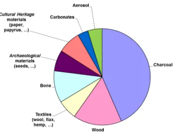
AMS measurements are performed using the dedicated accelerator beam line (Fedi et al. 2007), whose main features are bouncer sequential injection, stripping with argon at 2.5MV terminal volt-age, ion discrimination by magnetic and electrostatic analysis on the high-energy side, and counting of the rare isotopes by a solid state silicon detector. Many materials have been treated so far (see Fig-ure 1), including charcoal, wood, paper, textiles, and bones. Quite recently, applications of 14C have
been also extended to environmental issues, working on shells or foraminifera and on aerosol sam-ples (Fedi et al. 2012; Bernardoni et al. 2013).
This article describes the state of the art of the AMS facilities at LABEC after the first years of activ-ity of the laboratory, focusing in particular on the equipment and the capabilities that the sample preparation laboratory for 14C measurements has so far acquired. Two different combustion and
1INFN Sezione di Firenze, via Sansone 1, 50019 Sesto Fiorentino (Fi), Italy. 2Corresponding author: Email: [email protected].
3Dipartimento di Fisica, Università degli Studi di Milano, e INFN Sezione di Milano, via Celoria 16, 20133 Milan, Italy. 4Dipartimento di Fisica e Astronomia, Università degli Studi di Firenze, via Sansone 1, 50019 Sesto Fiorentino (Fi), Italy.
graphitization lines are installed: one is dedicated to archaeometric and geological applications (i.e. those applications that we can now consider as routinely performed); the other one has been espe-cially designed to be dedicated to aerosol samples. The latter allows us to analyze the different frac-tions of carbon present in the atmospheric aerosol collected on filters, to perform source apportion-ment studies thanks to the measureapportion-ment of 14C in either the total carbon (TC) or in the separate
fractions of organic and elemental carbon (OC and EC, respectively). In the following, we will describe the main characteristics of the 2 combustion and graphitization lines, also discussing pos-sible limitations of their usage. Finally, we will show a case of 14C dating of organic material
col-lected in an Etruscan bronze statue, showing an example of the flexibility of use of the preparation lines installed in the lab.
THE COMBUSTION AND GRAPHITIZATION LINE FOR “GENERAL” PURPOSES
The “standard” combustion and graphitization line at INFN-LABEC for general purposes, e.g. archaeometric applications, is principally based on a CN elemental analyzer (Thermo Flash EA 1112) to extract and isolate the gaseous CO2 from the sample to be dated, on a vacuum line with a
LN2 spiral trap to condense the evolved CO2, and on several reactors where the CO2 is converted to
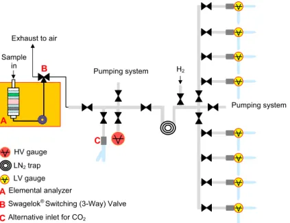
graphite by the reaction with hydrogen at high temperature (600 C) and in the presence of iron powder as catalyst (Alfa Aesar iron, pellets <10 µm). Figure 2 shows the schematic layout of the setup.
The use of the elemental analyzer (EA) to burn samples to be graphitized has some advantages: a fast combustion with the self-built possibility to simply separate CO2 from the other evolving
prod-ucts (water, sulfur, nitrogen); the possibility to directly measure the C/N ratio with no need to collect a separate fraction of the sample (this can be indeed useful when preparing bone samples; Sciré Calabrisotto et al., these proceedings); a good reproducibility of the time intervals characterizing the transfer of CO2 to the graphitization line, giving us the possibility to easily run the process by an
automatic system, too. However, some disadvantages should be recognized as well: some memory effects may occur, which, although kept small by appropriate procedures of “no sample”
combus-Figure 1 Distribution of the materials of samples treated and measured at INFN-LABEC since installation of the new accelerator (processing of samples like carbonates and atmospheric aerosol has been available for the last 3 yr only).
tion after each sample combustion to rinse the column. These questions may start to become rele-vant to the accuracy of the final dating as when burning in sequence very old and modern samples. Moreover, some of the combustion parameters, such as the amount of injected oxygen, can only be regulated within a limited range. Finally, the period of the overall combustion process cannot be set, as it depends on the Dumas combustion characteristics of the EA. This can represent a limit in some cases, e.g. when trying to burn blank carbonate samples as marble or pure graphite-like samples (see below).
This sample preparation line has been recently refurbished and upgraded, to change hardware parts that might have deteriorated since their first installation in 2004 and to enhance the performance (both in terms of quantity of processed samples and reliability of preparation) of the laboratory:
• The EA was coupled to the graphitization line through a new Swagelok® 3-way valve to easily
switch the flowing gases; this valve was chosen with a special L-flow path and a reduced size orifice to minimize the possibility of cross-port flow;
• The number of reactors was doubled to graphitize up to 8 samples in parallel;
• A new inlet connection was added to easily transfer the gaseous CO2 obtained from samples
that are not combusted in the EA (see C in Figure 2);
• The first CO2 spiral trap in the graphitization line was replaced with a flat spiral for a better
tem-perature homogeneity when dipping it into liquid nitrogen (see also Calzolai et al. 2011); • The use of Viton® O-rings was minimized to improve the vacuum level in the line and to reduce
possible effects of contaminations (Swagelok tube fittings with stainless steel ferrules, and weld fittings, were mostly used).
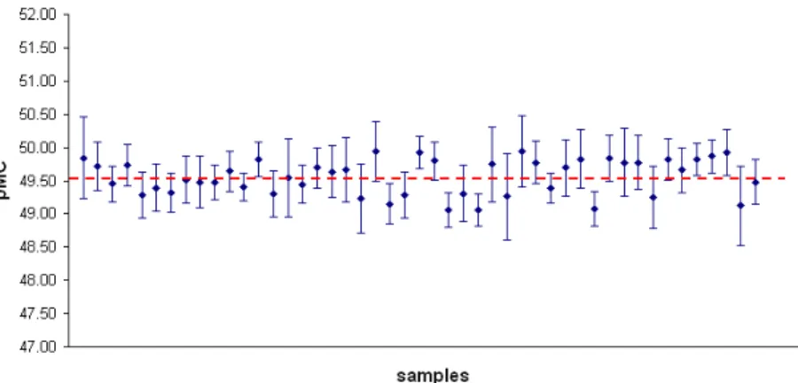
Figure 3 shows the 14C concentrations measured in IAEA C7 samples (the oxalic acid reference
material supplied by the International Atomic Energy Agency with a certified 14C concentration of
49.53 ± 0.12 pMC) prepared since 2010, when the main changes on the previous setup were applied. The 14C concentrations reported in the figure were calculated starting from the measured 14C/12C
Figure 2 Schematic layout of the combustion and graphitization line for general purposes
Pumping system Sample in H 2 Pumping system LN2 trap HV gauge LV gauge A C B Exhaust to air Elemental analyzer
Alternative inlet for CO2
Swagelok®
Switching (3-Way) Valve A
B C
isotopic ratios, correcting for background and isotopic fractionation (13C/12C ratios also measured
along the accelerator beam line), and normalizing to NIST oxalic acid II standard samples. The agreement between the experimental data and the expected value is satisfactory, demonstrating the accuracy of the overall procedure.
Other reference materials are often prepared and measured as secondary standards, and also confirm the accuracy of the measurements:
IAEA C2: 41.68 ± 0.43 pMC (consensus value 41.14 ± 0.03 pMC); IAEA C5: 23.03 ± 0.29 pMC (consensus value 23.05 ± 0.04 pMC); VIRI D: 2860 ± 46 yr BP (consensus value 2836 ± 4 yr BP); VIRI S: 109.59 ± 0.82 pMC (consensus value 109.96 ± 0.04 pMC).
The concentrations and the uncertainties above are reported as average and standard deviations cal-culated over all the measured samples, respectively. The 14C concentration measured in processed
blank samples is of the order of 0.5 pMC, being limited by the EA rather than the graphitization line. THE COMBUSTION AND GRAPHITIZATION LINE FOR AEROSOL SAMPLES
The other sample preparation line installed in the laboratory was specifically designed to meet the requirements of 14C measurements in aerosol samples. Actually, carbon is one of the major
compo-nents of aerosol, where it is found as both elemental carbon (EC) and organic compounds (organic carbon, OC). A key point for 14C measurements in aerosol samples is the possibility to physically
separate the different carbonaceous fractions, obtaining from them different samples for 14C
analy-sis. This type of separation is fundamental in order to get a complete apportionment of the carbon-aceous aerosol sources, i.e. to estimate the contributions from fossil fuels and from modern sources and, among the latter, from biomass burning and biogenic sources (Szidat et al. 2006). EC/OC sep-aration is based on thermal protocols including many steps at different temperatures and combustion atmospheres (oxidizing/inert) (Szidat et al., these proceedings).
Figure 3 Radiocarbon concentrations measured since 2010 until present (July 2012) in standard IAEA C7 samples, normalizing to NIST oxalic acid II standard samples. The certified 14C con-centration (49.53 ± 0.12 pMC) is indicated by the dotted line. The experimental uncertainty reported for each sample concentration corresponds to 1.
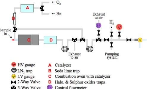
A detailed description of our aerosol sample preparation line can be found in Calzolai et al. (2011). Briefly, it is based on 4 parts (see Figure 4): 1) cleaning of the carrier gases; 2) combustion of the sample; 3) isolation of the CO2; and 4) graphitization. Cleaning of the carrier gases (namely He or
O2 depending on the desired combustion atmosphere) is accomplished by a soda-lime trap after any
possible carbonaceous impurity has evolved to CO2 thanks to a catalyzer. The combustion system
guarantees all the features needed for thermal OC/EC separation, as all the combustion parameters (temperature, time, and atmosphere) can be set by the operator and changed according to the adopted separation protocol. The combustion system is based on an oven (specifically designed and in-house built) provided with a catalyzer and a suitable heating coil. With this oven, temperature can be raised up to 1000 C at a quick rate up to 200 C/min. Moreover, both the combustion atmosphere and time can be set by the operator. During the combustion, a series of chemical and thermal traps allows the separation of the CO2 from the other gaseous combustion products and from the carrier
gas. Afterwards, the CO2 trap is filled with He (taking advantage of the shortcut that allows the
gases to be injected directly into the trap, bypassing the oven), cooled down to LN2 temperature,
connected to the last part of the line, operating under in-vacuum conditions and devoted to graphiti-zation, and evacuated. Finally, CO2 is graphitized in a reactor similar to those installed in the sample
preparation line for “general” purposes.
Specific combustion protocols were developed for the separation and the analysis of the aerosol car-bonaceous subfractions EC and OC (Bernardoni et al. 2013); for the study of the whole carbon-aceous fraction (i.e. total carbon, TC), a 20-min combustion at 800 C, in a 100 cc/min oxygen flow, has been adopted. The sample preparation line was found to have a 100% efficiency for TC samples prepared from different materials (e.g. NIST oxalic acid II, Alfa Aesar graphite, aerosol samples), including in such evaluation the efficiencies for every single step, such as combustion, trapping, transfer, and graphitization (Calzolai et al. 2011).
For 450-µg C samples, the background level was estimated to be about 0.4 pMC (it is worth noting that the expected minimum 14C content in the aerosol carbonaceous fractions is generally expected
to be about 1 order of magnitude higher than this).
An Example of Application on Charred Organic Material
Samples with a complex graphitic structure (e.g. burnt residues) require a highly oxidizing environ-ment, characterized by a large amount of combustive agent and high temperatures for long times, to achieve a complete combustion. According to our experience, for this kind of sample, the flash com-bustion in the elemental analyzer may not be sufficient. Instead, the aerosol preparation line, in par-ticular the burning oven, although specifically developed for aerosols, allows us to select the com-bustion parameters with no limitations, leading to a full comcom-bustion of the sample.
An example of charred organic material can be shown by some of the organic residues in the clay matrix used to model the body of a bronze sculpture. Many different materials are usually found in the soil, such as animal hair, straw, charcoals, and general charred matter. The latter typically con-sists of amorphous carbon, and is the result of the combustion at the high temperatures (~400– 500 °C) required for realization of the artworks.
To better trace the framework of its origin and its later discovery, characterizing the history of the preservation of this artwork, we were asked to date the organic material collected from the inner part of a famous Etruscan bronze statue, the Chimaera of Arezzo (see Figure 5), now at the National Archaeological Museum in Florence. The statue was discovered near Arezzo (Tuscany, Italy) in 1553, and was immediately taken to Florence at the Medici court. It represents the mythological beast of Chimaera, with the body and the head of a lion, the tail of a snake, and a head of a goat on its back. According to Greek mythology, the Chimaera was a monster, spitting fire from its mouth, which frightened the region of Asia Minor. The statue is known as one of the best examples of Etr-uscan bronze art and is attributed to a period between the 6th and 5th century BC. However, it is also known that, since its discovery, it has undergone several “restorations” during the centuries. For example, the tail was discovered later and applied to the body only during a restoration in the 18th century AD, even though in the wrong position. Nonetheless, the body of the animal has remained original.
For 14C dating, we collected by scalpel some burnt organic residues from the inner part of the mouth
of the statue. First, we observed the collected material under an optical microscope to remove the traces of silicates and metallic compounds, then we treated the organic residues using 1M HCl at high temperature (~80 °C) to remove any carbonates. To reduce the sample to graphite, the aerosol sample preparation line was used, exploiting the TC combustion protocol (see above). We could not
Figure 5 Photograph of the Chimaera of Arezzo, now kept at the National Archaeological Museum in Florence.
exclude that some metallic residues had been left in the sample matrix and the EA appeared to be unsuitable for the combustion, as discussed above. Primary standard samples (from NIST oxalic acid II), secondary standard samples (from IAEA C7), and blank samples (from Alfa Aesar pure graphite) were also prepared using the aerosol combustion and graphitization line.
Table 1 shows the result of dating. The calibration of the measured 14C age was performed using
OxCal v 4 (Bronk Ramsey 2009) and the IntCal09 calibration curve (Reimer et al. 2009). The result is compatible with the period during which the statue was discovered. This was attributed to the fact that we might have dated not the original organic matrix but something deposited later. This inter-pretation is consistent with historical documents: in fact, according to the chronicles of the period, the statue was exposed during the celebrations of the Florentine aristocracy, when torches were lighted just inside the Chimaera mouth to reproduce the mythological fire spitting (S Siano, personal communication). We thus expect to have dated those organic residues.
CONCLUSIONS
Since its start in 2004, AMS activity at LABEC has rapidly increased, and today we are able to pro-cess a significant number of samples per year, and to treat most of the materials of interest for 14C
analysis. The sample preparation line for “general” purposes fulfills the requirements for most of the archaeological and geological samples. A recently installed sample preparation line devoted to aero-sol analysis allows us to perform 14C measurements on the separate carbonaceous components of
particulate matter. The latter sample preparation line can also find applications for other samples when the choice of the combustion parameters is required, as in the presented case study.
ACKNOWLEDGMENTS
The financial support of Regione Toscana (in the framework of the TEMART project - POR CReO/ FESR 2007–2013) is gratefully acknowledged for the positions of M E Fedi and G Calzolai within INFN.
REFERENCES
Table 1 14C dating of the organic residues collected in the inner part of the mouth of the Chimaera
of Arezzo. The measured 14C concentration and corresponding 14C age are quoted at 1
uncer-tainty; the calibrated age is quoted at 95% of probability.
14C concentration (pMC) 14C age (yr BP) Calibrated age
Chimaera 95.18 ± 0.52 395 ± 45 AD 1430–1635
Bernardoni V, Calzolai G, Chiari M, Fedi M, Lucarelli F, Nava S, Piazzalunga A, Riccobono F, Taccetti F, Valli G, Vecchi R. 2013. Radiocarbon analysis on organic and elemental carbon in aerosol samples and source apportionment at an urban site in Northern Italy.
Jour-nal of Aerosol Science 56:88–99.
Bronk Ramsey C. 2009. Bayesian analysis of radiocar-bon dates. Radiocarbon 51(1):337–60.
Calzolai G, Bernardoni V, Chiari M, Fedi ME, Lucarelli F, Nava S, Riccobono F, Taccetti F, Valli G, Vecchi R. 2011. The new sample preparation line for radiocar-bon measurements on atmospheric aerosol at LABEC. Nuclear Instruments and Methods in Physics
Re-search B 269(3):203–8.
Chiari M, Migliori A, Mandò PA. 2002. Measurement of low currents in an external beam set-up. Nuclear
In-struments and Methods in Physics Research B 188(1–
4):162–5.
Chiari M, Lucarelli F, Mazzei F, Nava S, Paperetti L, Prati P, Valli G, Vecchi R. 2005. Characterization of airborne particulate matter in an industrial district near Florence by PIXE and PESA. X-Ray Spectrometry 34:323–9. Fedi ME, Cartocci A, Manetti M, Taccetti F, Mandò PA.
2007. The 14C AMS facility at LABEC, Florence. Nu-clear Instruments and Methods in Physics Research B 259(1):18–22.
Fedi ME, Alvarez-Iglesias P, Caforio L, Calzolai G, Ber-nardoni V, Chiari M, Nava S, Taccetti F, Vecchi R.
2012. Applications of radiocarbon measurements in environmental studies at INFN-LABEC, Florence.
EPJ Web of Conferences 24:07002,
doi:10.1051/epj-conf/20122407002.
Giuntini L, Massi M, Calusi S. 2007. The external scan-ning proton microprobe of Firenze: a comprehensive description. Nuclear Instruments and Methods in
Physics Research A 576(2–3):266–73.
Giuntini L, Lucarelli F, Mandò PA, Hooper W, Barker PH. 1995. Galileo’s writings: chronology by PIXE. Nuclear Instruments and Methods in Physics
Re-search B 95(3):389–92.
Lucarelli F, Nava S, Calzolai G, Chiari M, Udisti R, Ma-rino F. 2011. Is PIXE still a useful technique for the analysis of atmospheric aerosols? The LABEC expe-rience. X-Ray Spectrometry 40(3):162–7.
Massi M, Giuntini L, Chiari M, Gelli N, Mandò PA. 2002. The external beam microprobe facility in Flor-ence: set-up and performance. Nuclear Instruments
and Methods in Physics Research B 190(1–4):276–82.
Reimer PJ, Baillie MGL, Bard E, Bayliss A, Beck JW, Blackwell PG, Bronk Ramsey C, Buck CE, Burr GS, Edwards RL, Friedrich M, Grootes PM, Guilderson TP, Hajdas I, Heaton T, Hogg AG, Hughen KA, Kaiser KF, Kromer B, McCormac FG, Manning SW, Reimer RW, Richards DA, Southon JR, Talamo S, Turney CSM, van der Plicht J, Weyhenmeyer CE. 2009. IntCal09 and Marine09 radiocarbon age calibration curves, 0–50,000 years cal BP. Radiocarbon 51(4): 1111–50.
Sciré Calabrisotto C, Fedi ME, Caforio L, Bombardieri L, Mandò PA. 2013. Collagen quality indicators for radiocarbon dating of bones: new data on Bronze Age Cyprus. Radiocarbon, these proceedings, doi: 10.2458/azu_js_rc.55.16353.
Szidat S, Jenk TM, Synal H-A, Kalberer M, Wacker L, Hajdas I, Kasper-Giebl A, Baltensperger U. 2006. Contributions of fossil fuel, biomass-burning, and bio-genic emissions to carbonaceous aerosols in Zurich as traced by 14C. Journal of Geophysical Research:
At-mospheres 111: D07206, doi:10.1029/2005JD006590.
Szidat S, Bench G, Bernardoni V, Calzolai G, Czimczik C, Derendorp L, Dusek U, Elder K, Fedi ME, Genberg J, Gustafsson Ö, Kirillova E, McNichol AP, Perron N, Santos GM, Stenström K, Swietlicki E, Ushida M, Vecchi R, Wacker L, Zhang YL, Prévôt ASH. 2013. Intercomparison of 14C analysis of carbonaceous aero-sols: Exercise 2009. Radiocarbon, these proceedings, doi:10.2458/azu_js_rc.55.16314.
Taccetti N, Giuntini L, Casini G, Stefanini AA, Chiari M, Fedi ME, Mandò PA. 2002. The pulsed beam facility at the 3 MV Van de Graaff accelerator in Florence: overview and examples of applications. Nuclear
In-struments and Methods in Physics Research B 188 (1–
4):255–60.
Taccetti F, Carraresi L, Fedi ME, Manetti M, Mariani P, Tobia G, Mandò PA. 2010. A beam profile monitor for rare isotopes in accelerator mass spectrometry: pre-liminary measurements. Radiocarbon 52(2):272–7.