Synthesis of Software Programs for
Embedded Control Applications
Felice Balarin,
Member, IEEE, Massimiliano Chiodo,
Member, IEEE, Paolo Giusto, Harry Hsieh,
Student Member, IEEE,
Attila Jurecska, Luciano Lavagno,
Member, IEEE, Alberto Sangiovanni-Vincentelli,
Fellow, IEEE,
Ellen M. Sentovich, and Kei Suzuki
Abstract— Software components for embedded reactive real-time applications must satisfy tight code size and run-time constraints. Cooperating finite state machines provide a convenient intermediate format for embedded system co-synthesis, between high-level specification languages and software or hardware implementations. We propose a software generation methodology that takes advantage of a restricted class of specifications and allows for tight control over the implementation cost. The methodology exploits several techniques from the domain of Boolean function optimization. We also describe how the simplified control/data-flow graph used as an intermediate representation can be used to accurately estimate the size and timing cost of the final executable code.
Index Terms— Boolean functions, estimation, finite state ma-chines, high-level synthesis, optimizing compilers, real-time sys-tems scheduling, software performance.
I. INTRODUCTION
A. The Context: Embedded Systems
Embedded systems are electronic components of a physical system such as a vehicle, a chemical plant, a nuclear plant, or a communications system, that typically:
• monitor variables of the physical system such as temper-ature, pressure, traffic, chemical composition;
• process this information making use of one or more mathematical models of the physical system;
• output signals that influence the behavior of the physical system to control its function and optimize its perfor-mance.
Embedded systems cover a broad range of applications, from microwave ovens and watches to telecommunication
Manuscript received April 7, 1998; revised October 21, 1998. The work of H. Hsieh was supported by Semiconductor Research Corporation (SRC) under Contract DC-324. This paper was recommended by Associate Editor R. Camposano.
F. Balarin is with Cadence Berkeley Laboratories, Berkeley, CA 94707 USA (e-mail: [email protected])
M. Chiodo and P. Giusto are with Cadence Design Systems, Inc., San Jose, CA 95134 USA.
H. Hsieh and A. Sangiovanni-Vincentelli are with the University of Cali-fornia at Berkeley, Berkeley, CA 94707 USA.
A. Jurecska is with Synopsys, Beaverton, OR 97006 USA. L. Lavagno is with Politecnico Di Torino, Torino 10129, Italy.
E. Sentovich is with Cadence Berkeley Laboratories, Berkeley, CA 94707 USA.
K. Suzuki is with Central Research Laboratory, Hitachi Ltd., Kokubunji, 185 Tokyo, Japan.
Publisher Item Identifier S 0278-0070(99)03962-7.
network management and control functions. These embedded systems are integrated onto the physical system itself and hidden from the user. The implementation of such systems can vary from a full hardware configuration, where all the tasks to be performed by the embedded system are translated into a suitable set of customized integrated circuits, to a full software implementation, where all the tasks are implemented as software routines run on a standard component, such as a microprocessor or a digital signal processor (DSP). While in the past hardware configurations dominated the field, today most of the applications are implemented in a mixed configuration, where software has the lion’s share. This shift has been basically due to the flexibility offered by software implementations and to the increasing importance of time-to-market considerations in engineering design.
B. The Problem: Software Synthesis
The bottleneck for the implementation of embedded systems has long been considered the development of software, its debugging, and its integration with the hardware components. Recently, it has been pointed out that the capability of ana-lyzing a system before a particular technology is chosen as a target implementation is of paramount importance to have “right-for-the-first-time” designs.
This scenario fueled the quest for a design methodology that favors system-level descriptions of functionality and con-straints, technology-independent verification, and automati-coptimized mapping from the system-level descriptions and constraints to software and hardware implementations. While hardware synthesis has been the object of considerable atten-tion over the recent past, much less attenatten-tion has been devoted to the process of software synthesis.
We informally distinguish between software synthesis and software compilation, according to the type of input specifi-cation. The term software compilation is generally associated with an input specification using C- or Pascal-like imperative, generally nonconcurrent, languages. These languages have a syntax and semantics that is very close to that of the implementation (assembly or executable code). In some sense, they already describe, at a fairly detailed level, the desired implementation of the software. We will use the term software synthesis to denote an optimized translation process from a high-level specification that describes the function that must be performed, rather than the way in which it must be implemented. Software synthesis can be, for example, the
C or assembly code generation capabilities of DSP graphi-cal programming environments, such as Ptolemy ([11]), of graphical finite state machine (FSM) design environments, such as StateCharts ([20]), or of synchronous programming environments such as Esterel, Lustre, and Signal ([19]).
This notion of software synthesis received much attention in the early 1970’s but results were mainly theoretical with little practical impact on software design practices. The lack of results of practical importance was mainly caused by the very wide range of possible applications that required heterogeneous models of computation and constructs, such as pointers, memory allocation, and recursion, that were too difficult to manipulate efficiently in an automatic fashion. C. Compiler Technology
On the other hand, compiling a high-level language into machine instructions has been the enabling technology for the extended use of computers for all kinds of applications. The progress of compiler technology has been exciting over the past 20 years. Compilers translate high-level constructs into an optimized set of machine instructions. This translation occurs in two basic steps: mapping from high-level constructs into intermediate code that is often processor independent, and mapping of the intermediate code into the actual “architecture” (instruction set and registers) of the processor to be used. The first step is optimized by applying a set of semilo-cal transformations to yield an intermediate representation that can be directly translated to more compact and faster code. The following steps deal with the architecture-specific transformations that include register allocation and instruction selection.
The use of semilocal, peep-hole optimization is justified on the one hand by the need for compiling code in reasonable time, on the other by the great variety of constructs to deal with. After all, it is often reported that the bottleneck in software debugging is compilation time.
D. Software versus Hardware Compilation
The analogy between hardware and software compilation has been known and exploited for a long time [16]. Hard-ware compilation (or high-level synthesis) [7], [27] involves functional and register allocation and scheduling, followed by component synthesis and optimization. Software compilation [1] traditionally involves register allocation and instruction selection, followed by local optimizations.
Exploiting the link between these two continues to be a fruitful avenue for research: technologies for each are continually advancing, and the two domains have traditionally had significant differences that have prevented the application of some techniques in each domain to the other. In particular, optimization has typically been more aggressive in hardware synthesis, while for software long compilation times have prevented global techniques from being employed.
In our context, hardware and software in a single system are synthesized together. This implies that the software part is derived from the same starting point as the hardware and, thus, is “hardware-like” and contains a small set of simple
constructs. For example, features like recursion, pointers and loop bounds that can be determined only at run-time, are not used, because they are hard (and in general even impossible) to implement in hardware. This software lends itself well to aggressive, global optimizations as are traditionally applied to hardware. As mentioned previously, we refer to this creation and optimization of restricted software as “software synthesis” rather than “software compilation.” We apply optimization techniques derived from the hardware optimization area to optimization of embedded software.
E. Restricted Application Domains
When we deal with specialized applications, such as DSP, the range of different constructs to consider is much more restricted than in general computing. Hence, more aggressive optimization is possible, and has indeed been attempted, yielding interesting results [26].
Most of the embedded systems applications do not require a wide variety of coding constructs. We strongly believe that in this class of systems, automatic optimization and verification can be pushed to a level that is unprecedented in “standard” compiler and operating system technology.
F. Our Environment and Requirements
To really decrease development time for embedded sys-tems, we have to select a high-level representation that is implementation independent and easy to use for a system designer, and then select a set of mathematically well-defined operations to translate and optimize this representation. Among all embedded systems applications, we chose to focus on control-dominated embedded systems, characterized by the importance given to the decision process that leads from a set of input events to a set of output events (reaction). The high-level representation of choice is an interconnection or network of communicating processes with FSM semantics. Today, FSM’s are commonly used in embedded system de-sign tools both explicitly (specified in graphical or textual form [20], [32]) and as an intermediate format ([8], [19], [35]).
G. TheFSMModel:CFSM’s
The use ofFSM’s for embedded control specification offers several advantages over apparently more powerful formalisms (such as unrestricted programming languages). First of all, they are easily understood and widely used even as informal specifications. Second, there are abundant theoretical and practical results concerning their manipulation (minimization, encoding, formal verification of properties, etc.).
Unfortunately “pure” FSM’s do not provide a very con-venient representation for systems that perform even a small amount of computation. It is then customary to extend them with the capability to perform assignments of expressions to variables, and to use relational operators to determine transition conditions. This mechanism increases the expressive power at the expense of the synthesis and verification capa-bilities (e.g., there is no longer a “canonical” form for such extended FSM’s, verification becomes much more difficult,
etc.). In our design methodology and tools, we have se-lected an extended FSM model called codesign FSM (CFSM), defined in [12] and [13]. This representation extends classical
FSM’s with arithmetic and relational operators, and assumes that CFSM’s interact via an asynchronous communication mechanism that allows great flexibility and expressive power. Even though throughout this paper we refer to CFSM’s as representation, our results on software generation can be applied to any extended FSM-based specification, like those mentioned above.
H. Our Approach to Software Synthesis
The purpose of this paper is to describe algorithms for a software synthesis system generating C code from FSM
specifications. This system includes optimization techniques that are either impossible or simply too expensive in the general compiler domain ([1]), but are very effective in our restricted domain. Moreover, unlike classical compilation algorithms, our software synthesis technique starts from a description of the function to be computed, rather than from an operational implementation of it. This allows the use of powerful optimization algorithms based on Boolean function manipulation methods. We tightly couple the optimization process with a fast and accurate timing and code-size esti-mation procedure to take into account constraints at a much finer granularity than is possible with a truly general-purpose compiler. We do not claim to have invented a new general purpose compiler, because the domain of applications is much more restricted.
Throughout this paper we make the following main assump-tions.
1) The specification is given as a network of CFSM’s. Note that even though such a specification is not biased toward any particular implementation, it does impose a network structure which we preserve during synthe-sis. This means that each CFSM is a synchronous, statically scheduled entity, while the network is asyn-chronous, concurrent, and dynamically scheduled. The granularity level is defined a priori by the designer, and the ordering of emission of output events is de-cided statically by our synthesis algorithm, with the objective of minimizing code size as discussed in Sec-tion III-B. A more global approach, in which the syn-chronous/asynchronous boundary can be chosen as part of the synthesis process, with the objective of simultane-ously optimizing code size and execution time is left to future research. Note that a growth of the synchronous islands (CFSM’s) typically induces:
• an increase in code size, due to the more complex transition function that must be computed;
• a reduction in execution time (if synthesis is per-formed using the techniques described in Section III-B, where the execution time of the control portion of the code depends almost entirely on the number of inputs and outputs of eachCFSM), due to:
—the reduction of communication and scheduling overhead;
—(possibly) the increased utilization of processor resources, due to exposing larger statically sched-uled units to the underlying C compiler. 2) A real-time operating system (RTOS) is used to activate
appropriately the tasks implementing theCFSM’s. Our synthesis procedure, in addition, provides execution time estimates that can be used either by a user or by an automatic RTOS generator to devise a scheduling policy that is guaranteed to meet the timing constraints. 3) An existing general-purpose C compiler is used to
transform the C code that we produce into machine code. This allows us to concentrate on domain-specific transformations, while leaving general ones such as reg-ister allocation and instruction selection to the general-purpose C compiler. Note that the C code that we produce is so simple and low-level that we can keep a very tight control over the resulting machine code, and the compiler cannot “undo” our optimizations. We use a control/data-flow diagram (called an s-graph, for software graph) as an intermediate data structure. The s-graph is simpler than general control/data-flow diagrams, because it needs only to represent a single function from a discrete domain (the set of input events and values) to a discrete domain (the set of output events and values). As such, it requires only conditional branch and assignment as primitives (augmented with arithmetic and relational expressions without side effects). The s-graph has a direct representation in C and can be translated with equal ease into object code by any available compiler. In this way, we can obtain good cost and performance estimates at any intermediate stage of the optimization process, without the need to compile the code and analyze the results.
Our software synthesis procedure is composed of the fol-lowing main steps:
1) optimized translation of the transition function of a given
CFSM into an s-graph;
2) s-graph optimization and code-size estimation; 3) translation of the s-graph into a target language; 4) scheduling of theCFSM’s and generation of the RTOS; 5) compilation into machine code to be run on the target
processor.
Step 1 consists of building an optimized binary decision dia-gram (BDD, [10]) for the transition function as an intermediate representation, to generate an initial s-graph corresponding to code that executes very fast, potentially at the expense of code size. It is based on a new result, described in this paper, that states the equivalence between:
• a multioutput multivalued function ;
• an s-graph computing , that is directly obtained from a
BDD representing .
Step 2 is similar to standard software optimization tech-niques based on control/data-flow diagrams (Section II con-tains a discussion of its relation to previous work). Thus far, we have generated C code in Step 3, though any target language is possible. Step 4 uses the software performance estimation package and classical real-time scheduling algorithms [24], [18] to schedule theCFSM’s while meeting the given timing
constraints. The compilation in Step 5 is done using existing C compilers for the target embedded processors.
The paper is organized as follows. Section II contains background information and a summary of theCFSMnetwork model. Section III contains the s-graph structure definition, its synthesis and optimization fromCFSM’s, C code generation, and software cost and performance estimation based on s-graphs. Section IV describes the functionality of the automat-ically generated RTOS. Section V shows some experimental results demonstrating the effectiveness of the approach.
II. PRELIMINARIES
A. Previous Work
1) Software Synthesis: Previous approaches to automated software synthesis for reactive real-time systems have started either from synchronous programming languages (e.g., Esterel, [8]), or from other high-level languages ([14] and [17]).
In the first case, the main problem is the identification of a single FSM equivalent to the Esterel specification, and its efficient implementation as a software program. Previous versions of the Esterel compiler (v3) produced a singleFSM, which resulted in a very fast implementation (as all the internal communication between modules disappears when the single FSM is produced), at the expense of code size. The versions from v4 on ([34]; see also [9]) maintain a multi-FSM representation, while ensuring that the global behavior is equivalent to that of a single FSM.1 Thus, the composition is never computed explicitly. This results in a code size that is usually linear in the size of the specification (in the worst case, it is proportional to the square of the size of the specification). The translation is done via the intermediate form of Boolean circuits, enabling logic optimization techniques to be used to reduce the final code size. However, these optimization techniques are applied to an abstract represen-tation of the final code, and no low-level or target-specific optimizations are available. Furthermore, the optimization is applied globally to the entire system, with no opportunity for optimizing on a module-by-module basis. Our approach, on the other hand, allows a finer tradeoff between size and speed:
• the designer can choose the granularity of the generated
CFSM’s, even if they are produced from an Esterel specification ([36]);
• the designer can manipulate theCFSM hierarchy during synthesis;
• the optimizations are done at a level closer to the final C-code implementation;
• optimizations include both Boolean-circuit based algo-rithms and decision-tree based algoalgo-rithms; thus far the decision-tree based algorithms have been more successful in producing compact code.
In the second case, the main emphasis is on the scheduling of operations derived from a concurrent high-level specifica-tion (e.g., hardware-C, [21]). The problem is that of choosing an order for potentially concurrent operations that satisfies
1See [7] for more on composition and causality.
the given timing constraints. In our case, we decompose the problem of satisfying timing constraints into two (possibly iterated) steps:
a) software generation for each CFSM;
b) scheduling of CFSM transitions to satisfy timing con-straints.
Thus, we can take advantage of the large body of research about scheduling for real-time systems (e.g., [24]) for the second step. On the other hand, some of the fine-grained scheduling algorithms described in [17] and [14], for exam-ple, can also be used to perform a preliminary optimization before our synthesis algorithm. This would allow an easier satisfaction of “short term” timing constraints (e.g., those dictated by a specific interface protocol implemented directly in software) which may be more difficult to satisfy with classical scheduling techniques (designed for “long term” response and input rate constraints).
2) Hardware High-Level Synthesis: Hardware high-level synthesis can roughly be divided into two stages: behavioral and register-transfer level (RTL). The input to the behavioral synthesis is a sequential specification, where timing of actions is not fixed. Its output is a collection of registers and a cycle-by-cycle specification of how the registers change. This is then the input to RTL synthesis, which mostly deals with the combinational specification of register transfers, and builds an optimized circuit for it.
Similarly to classical compilers, behavioral synthesis usually operates on a description that is structurally very similar to the original specification (e.g., CFG graph). However, the combinational specification at its output no longer bears this resemblance, but it is rather in a form that facilitates powerful combinational logic optimizations (e.g., sum-of-products or
BDD’s [7]). In our approach (enabled by domain restric-tions), we transform the original sequential specification into such a form. This enables us to extend combinational logic optimization techniques (BDD’s, to be more precise) to the optimization of sequential programs. In general, these opti-mizations are more powerful than local transformations used by compilers and behavioral synthesis systems.
Perhaps not surprisingly, the relative value of optimization techniques changes in the software area. For example, while
BDD’s are used extensively in combinational logic synthesis to represent and manipulate Boolean functions (e.g., [7], [25], and [31]), it is generally accepted that they are not a very good structure for circuit implementation (except for low-power [22]). In contrast, we will show that BDD-like structures are very efficient (though quite unreadable) program implementations.
The approach of [7] used BDD’s to represent control functions in a high-level synthesis system. In their work, the application is purely to hardware; the authors did not make special considerations for software such as optimization based on estimations of timing of instruction execution. They derive the control functions and build the BDD for them on-the-fly. Several ordering methods are used, but they are all static heuristics for obtaining a good initialBDD.BDDoptimization based on reordering is not applied. Furthermore, that work
does not exploit interleaving of input and output variables (or at least, does not mention this).
3) Hardware Simulation: Surprisingly enough, the closest relatives of our software synthesis techniques come from the area of cycle-based hardware simulation. Both [28] and [3] are aimed at solving a problem that is quite similar to ours: efficiently computing on a sequential machine the transition function of anFSM. Both approaches rely on a BDD representation of the transition function, and exploit the fact that, given an input and present state assignment, there exists a uniqueBDDpath that can be used to compute the value of the next state and output functions. This means that a single-threaded sequential execution of thisBDD can be efficiently implemented on a standard workstation.
Even though the basic problems are related, there are a number of differences.
1) Their starting point is a large synchronous circuit repre-sented at the gate level, hence, their main problem is to efficiently represent theFSMwithout a blow-up of the
BDDsizes (mostly due to data computations represented in FSM form).
Our starting point is an explicit representation of an Extended FSM, in which data computation are repre-sented using explicit arithmetic operators. Hence, we do not suffer from blow-up problems due to the data part. The BDD’s representing the control part suffer from exponential growth less often, and the designer can control this phenomenon directly, by changing the
CFSM granularity.
2) Their target is execution on high-end workstations. Hence, they can afford to use very large BDD’s, and even to use multivalued variables to represent sets of binary variables, thus, causing large lookup tables to be generated. Their main problem is cache and translation lookaside buffer thrashing due to the huge size of the generated tables. They also use a simple and fast table lookup algorithm to implement the BDD’s using the data section of the object code.
Our target is execution on often very small embedded controllers, in which memory is a very expensive and scarce resource. Hence, we implement the BDD’s directly in executable code, i.e., in the text section of the object code. In this way, we can use the efficient encoding of the BDD branching structure provided by the instruction set encoding of the target processor (often using fewer bits of address for near jumps).
For this reason, our techniques and results are quite different from those of [28] and [3].
B. Binary Decision Diagrams
The BDD is a key data structure as an intermediate repre-sentation for our software optimization techniques. A binary-decision diagram (BDD[2], [10]) is an efficient representation for storing and manipulating Boolean functions. A BDD is a directed acyclic graph with a root node for each output function and leaf nodes representing the value of each out-put function for each inout-put minterm. Each nonleaf node is
associated with an input variable, and each of the two out-edges of the node is associated with the value of the variable (zero or one) along that branch. The representation is made compact (reduced) by sharing common functional subgraphs. Given a function and an ordering of the input variables, the reduced-ordered BDD(simply called BDD in the following) is a canonical form for .
While the size of the BDD may be exponential in the number of inputs for any ordering, in many practical cases a good ordering can be found that produces a BDD of manageable size. Functional operations on the BDD take at most space and time ( is the number of nodes in the BDD); equivalence checking between two BDD’s requires only a graph isomorphism check. The canonicity property of BDD’s, efficient BDD package implementation, and recent improvements in variable ordering strategies have made BDD-based algorithms efficient and effective for a variety of problems involving Boolean function manipulation. C. Characteristic Functions
Multioutput functions (or, equivalently, sets of functions defined on the same domain) can be represented by their characteristic functions. A single-output binary-valued
func-tion , where
and , represents the multioutput multivalued
function if . The
same notation can also be used to describe a relation , as .
The function resulting when some argument of a function is replaced by a constant is called a restriction (or cofactor) and is denoted . The projection of a function onto a space orthogonal to (or smoothing of by , or existential quantification of in ) is denoted . That is,
if , then .
The support of an output variable of a multioutput function is the set of inputs upon which essentially depends. More precisely, an input variable belongs to the support of
if .
D. Network of Codesign FSM’s
Our model of a control-dominated reactive system (orig-inally proposed in [12] and [13]) is globally asynchronous locally synchronous (GALS) network of CFSM’s communi-cating via events. The interested reader is referred to [5] for a more complete description of the CFSMmodel and of the implementation choices that we have made.
An input or output CFSM event occurs at some point in time and may carry a value which is represented by a discrete-valued variable (cfr. the notion of signal in Esterel). An example of a valued event is a temperature sample, or a key hit on a keyboard; an example of a value-less (also called “pure”) event is an excessive pressure alarm, or a reset button. Each CFSM receives atomically (locally synchronous), or detects, a snapshot of its input events, and performs its calculations independently and asynchronously of other CFSM’s (globally asynchronous). As a result of the computation, it may sometimes later change state and/or
emit output events. Each event, with or without a value, is associated with a Boolean flag, indicating the presence of the event, which is true in the time interval between its emission and its detection. The value of an event is updated by the emitter:
• ideally, at the same time the presence flag is set; • in practice, especially in a software implementation,
“some small amount of time before” the presence flag is set2;
Each input event may be detected at most once at any time after its emission: once detected, it is no longer present at the input of theCFSM. ACFSM’s reaction to an event occurrence is defined by the transition function of the CFSM. The transition function synchronously maps the set of input events and values onto the set of output events and values, possibly
based on its internal state: .
A CFSM begins its reaction (computation of the transition function) to an input event after a sensing delay (sd) that is greater than or equal to zero. It completes its reaction by emitting some events after a reaction delay (rd) that is strictly greater than zero.
The model of communication is, in general, asynchronous: the emission of events by the CFSM’s in the network may happen at any time and independently. Because of the asyn-chrony, there is no guarantee that aCFSMwill detect an event before it is emitted again. Hence, it is possible that an event and its value are overwritten and lost. This is equivalent to the assumption that there is a buffer of length one between each
CFSM and for each event.
Synchrony and Asynchrony: In our framework, the CFSM
model is used throughout the design process and, in particular, as a mechanism to capture the design intent. We strongly believe that at the highest levels of abstraction, restrictive hypotheses have to be carefully evaluated to make sure that designs of practical relevance can be appropriately modeled. For this reason, we have chosen the communication mech-anism to be asynchronous since this model does not overly restrict the implementation domain to be considered.
We also believe that the restriction imposed by synchronous languages such as Esterel, although very convenient from the analysis point of view, is too strong at the highest level of abstraction. The synchronous hypothesis assumes that the reaction to external stimuli of the network of concurrent processes occurs in zero time, i.e., all internal communication can be abstracted away. As a result, it is theoretically possible to extract a single, albeit possibly very large,FSMequivalent to the network of concurrent processes. This implies that formal verification and other analysis techniques based on standard FSM’s are possible. On the other hand, this also may imply a costly final implementation (where one must ensure that the synchrony hypothesis is indeed valid, that is, that the system reacts much faster than its environment) and a small solution space (where one must force the validity of the hypothesis). In particular,
2This choice was made in order to allow an efficient implementation in
software, without the need to disable interrupts for long periods of time to implement emission atomicity.
the synchronous hypothesis implies that the behavior of a correct implementation of a synchronous program must be analogous to that of a combinational circuit (except for waiting statements, which are equivalent to registers). As such, a correct heterogeneous implementation (mixed hardware and software) requires the solution of a very complex run-time scheduling problem, equivalent basically to hardware simulation.
Our asynchronous communication model is inherently non-deterministic. This feature certainly makes the design and veri-fication process more complex, because all possible resolutions need to be considered. On the other hand, nondeterminism enables us to easily model the unpredictability of the reaction delay of a CFSM both at the specification level, where we need to represent different implementation styles that imply quite different reaction delays, and at the implementation level, where delays may still remain intrinsically unpredictable. Specifically, a software implementation has a delay that may be much larger than a hardware one. Moreover, if soft-ware is based on a RTOS supporting preemption, it has reaction delays that depend on the context and as such, in our opinion, cannot be represented accurately with a model based on a synchronous hypothesis. Note that our model does allow one to choose a synchronous implementation that fits into the synchronous hypothesis by modeling the em-bedded system as a single CFSM, but of course does not force one to choose such an implementation from the very beginning.
The rationale for the introduction of this model is based on the following considerations.
• A network of components can express a complex behavior while keeping the complexity of each component at a reasonable level.
• The behavior specification is extended with the use of arithmetic (or other) operations to be able to represent embedded systems where real-valued variables are con-trolled.
• The reaction and sensing delays are useful in modeling and constraining the timing behavior of heterogeneous implementations (software may take an a priori unknown number of clock cycles to execute a task represented by a CFSM while a straightforward synchronous hardware implementation takes only one cycle).
• An asynchronous communication mechanism is more ef-ficient for representing the interaction among tasks in an embedded system, where timing constraints are tight and synchronous implementations may cause unnecessary delays because the common pace of the system must be slow enough to accommodate the slowest communication link.
III. SOFTWARE GRAPHS
This section begins with the definition of an s-graph in Section III-A. The synthesis and optimization of an s-graph from a CFSMtransition function is described in Section III-B. Finally, software cost estimation based on the s-graph is described in Section III-C.
A. S-Graph Definition
In this section, we define more precisely the control-flow graph that we use as internal representation of the CFSM
transition function.
Definition 1: An s-graph is a directed acyclic graph (DAG) with one source and one sink. Its vertex set contains four types of vertices: BEGIN, END,TEST, and ASSIGN. The source has typeBEGIN, the sink has typeEND. All other vertices are of type TEST or ASSIGN. Each TEST vertex has two children true and false .3 Each BEGIN or
ASSIGNvertex has one child next only. Any nonsource vertex can have one or more parents. An s-graph is associated
with a set of input and output variables ,
ranging over finite domains , respectively.
• EachASSIGNvertex is labeled with an output variable
, and a -valued function . In
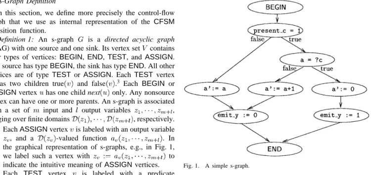
the graphical representation of s-graphs, e.g., in Fig. 1,
we label such a vertex with to
indicate the intuitive meaning ofASSIGN vertices. • Each TEST vertex is labeled with a predicate
, whose truth value determines which child will be executed.
A simple s-graph is shown in Fig. 1. It corresponds to the reactive behavior, represented in Esterel, as shown at the bottom of the page.
1) To each valued input signal we associate two input s-graph variables, one Boolean and one with the same domain as the signal, while a pure input is associated only with the Boolean input. For example, input signal
c is associated with:
• a Boolean variable present_c, indicating that c
is present in the currentCFSMinput snapshot; • an integer variable ?c, holding its value.
2) Similarly, to each valued output signal we associate two output s-graph variables. For example, output signal y
is associated with Boolean variableemit_yindicating
3The implementation described in Section V allows more than two children.
The extension of the definitions and theorems to the more general case is trivial.
Fig. 1. A simple s-graph.
whether y is being emitted in the current synchronous reaction. Ifywere not pure, it would also be associated with an output variable holding the value to be emitted. 3) To each state variable we associate one input and one output s-graph variable (no presence information is associated with state variables, of course). For example, input variable a and output variable a’ correspond to the values of state variableain the current and the next reaction, respectively.
The Esterel statement await c is implemented by the
TEST node checking if present_c is 1. The outermost loop is implemented by the RTOS, that will call the C code synthesized from the s-graph every time it must execute a reaction (a CFSM transition), i.e., every time it has at least one present input event.
The s-graph model resembles branching programs ([23], [29]) and binary decision diagrams. Both branching programs andBDD’s are different from s-graphs because they allow:
• only single-variable predicates onTEST nodes;
• assignments to only a single output variable (as the last level of nodes).
module simple: % CFSM name
input c:integer; % integer input signal output y; % pure output signal var a:integer in % local state variable
loop % loop forever
await c; % wait for c to be present
if a ?c then % if a is equal to the value of c a 0; emit y; else a a 1; end if end loop end var end module
We will see in Section III-B, though, that there is a close con-nection between aBDDrepresentation of aCFSM transition function and an s-graph computing it.
The evaluation of the multioutput function computed by an s-graph withBEGINnode , input variables, and output variables uses the following algorithm. Let denote a vector of temporary variables, each uniquely associated with an input or an output variable,4 and denote an uninitialized value. procedure evaluate (v: vertex; :variable) begin
for
if is an input then assign to it the corresponding else
eval step (next(v), ) for
if is an output then assign it to the corresponding return
end
procedure eval step (v:vertex; :variable) begin
if is aTESTthen
if then
eval step (true(v), )
else eval step (false(v), )
else if is anASSIGN then
eval step (next(v), ) end
Definition 2: Let be an s-graph, and let be partitioned among input and output variables as assumed by procedure evaluate.
is functional if every output variable :
1) is assigned by eval_step at least one defined (i.e., different from ) value for each combination of values of the input variables;
2) has a defined value whenever a predicate or a function depending on is visited by eval_step.
It is easy to show that for a functional s-graph, evaluate defines a completely specified I/O function, i.e., that
for all
It is also easy to check that a nonfunctional s-graph denotes: • either an incompletely specified function, if condition 1)
in Definition 2 is violated;
• or a relation between the input and the output variables, if condition 2) in Definition 2 is violated. In this case, we consider a nondeterministic execution of evaluate, in which the undefined value can mean any value in the domain of the corresponding variable. Then an element
of belongs to the relation
if one possible choice in the evaluation of a TEST or
ASSIGN node with an undefined predicate or function can yield it.
4In Section III–B2, we will show how to compute a heuristically “good”
association in order to minimize the s-graph size.
This fact can be used in optimizing the s-graph, as briefly explained in Section III-B2.
B. S-Graph Implementation and Optimization
Software generation for a givenCFSMproceeds by generat-ing the initial s-graph from the transition function, optimizgenerat-ing the s-graph, and translating it into C code.
1) Handling of Extended FSM’s: The transition function of a CFSM in general involves both Boolean (or symbolic multivalued) and (bounded) integer variables. The former are used in the reactive control part, while the latter are used in the computational data part. This paper focuses on optimizing control-dominated specifications and, hence, the discussion in the remainder of this section is mostly devoted to an efficient implementation of the reactive control component. However, real specifications seldom consist completely of reactive control. Hence, we adopt a mixed representation of a CFSM.
In this paper, we represent theCFSMtransition function as a composition of the following:
• set of tests on input and state variables;
• set of actions, which can be either output emissions or assignments to state variables;
• the reactive function mapping subsets of to subsets of , represented by its characteristic function
.
For example, for the ESTEREL module in Section I tests are present_c and a ?c, actions are a’ a, a’ 0,
a’ a+1, andemit_y, and the reactive function is
Tests and actions will be implemented as expressions in the target language. The reactive function is just a Boolean function, for which we construct an s-graph, as described in the next section. The procedure produces an initial implemen-tation, that can be optimized using a variety of techniques.
Conceptually, theCFSM transition function is executed in three phases.
a) Tests are evaluated to determine the values of input variables of the reactive function.
b) The s-graph of the reactive function is evaluated to determine the values of its output variables.
c) Actions corresponding to output variables with value one, are executed.
In practice, these three phases are interleaved. Test are evalu-ated as they are needed during s-graph evaluation, and actions are executed as soon as the corresponding variable is known to be one.
Throughout this paper, we assume that expressions do not have side effects and, hence, that their execution can be reordered at will in order to optimize, e.g., code size as described later. For the basic CFSM model as described
previously, the only expression that possibly has a side effect is a division by zero, that may cause an arithmetic exception. We will, hence, assume that division is implemented safely (by first checking if the divisor is zero) and that a correctCFSM
never uses the result of a division by zero (even though it may perform it as part of its evaluation).
2) Initial S-Graph Implementation: The initial s-graph is built recursively starting from the reactive function, as follows.
The input and output variables (where
and ) are visited based on an initial arbitrary ordering. The assignment functions are computed based on the Shannon
decomposition . Procedure build is called
with an initial variable index of zero, and the function set to the reactive function. As we will see below, the choice of the ordering influences the form of the final s-graph (specifically the relative mix ofTEST andASSIGN nodes).
procedure build( : variable; : index; : function) begin
if then
create aBEGINvertex
next build
else if then
create theENDvertex ; else if is an input, then
create aTESTvertex with ;
true build
false build
else if is an output, then
create anASSIGNvertex labeled with and
next( ) build return reduce end
We assume that the reduce function, called in the last step, ensures that a graph with root has no isomorphic subgraphs, exactly as in BDD construction [10]. In particular, reduce should eliminate all but one ENDnode.
We can now show the correctness of this algorithm.
Theorem 1: Let be the
charac-teristic function of multioutput function , such that , and let be theBEGINvertex of the s-graph
returned by procedure build( ).
Then, for all
Proof: Consider an assignment of values to the input variables of , and an arbitrary output
.
Traverse the s-graph up to an ASSIGN node labeled with (from the definition of build, it follows there exists exactly one such node on any path from BEGIN
to END). Suppose, without loss of generality, that in this traversal, TEST nodes labeled with the first input variables and ASSIGN nodes labeled with the first output variables have been visited. When build is called
for node , . Hence,
(a function which
depends on the unvisited inputs only). The
value of is one if and only if (i.e., the
value assigned to is correct), because 1) by definition the
characteristic function is ;
2) the smooth function distributes over functions that are independent of the smoothing variable:
if is independent of . 1) and 2) imply that .
Note that the mapping from the transition function to the s-graph is not unique since it is based on the ordering of the variables. Section III-B3 discusses the influence of this choice over the characteristics of the generated code.
Moreover, the input to this algorithm need not always be a function, but could also be a relation (e.g., when nonde-terminism is used to describe design freedom). In that case, with a modification to theASSIGN function as indicated below, there may be cases in which the value assigned to still depends on (as well as on any input still to be tested).
The simplest case, when , corresponds to
a classical “don’t care”, because can be assigned any value (including the cheapest option of no assignment) and still be compatible with the characteristic function.
This flexibility can be exploited to minimize the size of the s-graph, because the ASSIGN label could in fact be any function which satisfies the conditions shown at the bottom of the page. Note that the two cases do not cover all possible input combinations and, hence, we have some flexibility in the implementation.
3) S-Graph Optimization:
a) Optimization by reordering: An s-graph can be opti-mized by reordering the nodes to minimize size and/or depth. In practice, it is more efficient to consider the ordering before
1) is one whenever is an output is an output is one and 2) is zero whenever is an output is an output is zero.
building the complete graph. There are three major classes of variable orderings.
i) Ordering each output after its support yields an s-graph where all the decision computation is done by
TEST’s.ASSIGNnodes are labeled only with actions on output variables (i.e., only with output variables and constants in the reactive function representation). ii) Ordering each output before its support yields an
s-graph without TEST nodes.
iii) All other orderings yield an s-graph with a mix of
TEST andASSIGN nodes.
b) Ordering outputs after their support: Our current im-plementation uses the first ordering scheme. In that case, it is easy to show that the structure of the s-graph corresponds exactly to that of a BDD representing CFSM’s reactive function. Informally,TESTnodes correspond toBDDnodes associated with inputs of the reactive function, whileASSIGN
nodes correspond to the outputs. Therefore, optimization of the s-graph can be done directly on theBDDrepresenting the
CFSM characteristic function.
We heuristically optimize the size of thisBDDby dynamic variable reordering, using the “sift” algorithm [31]. Sifting moves one variable at a time up and down in the ordering, and freezes it in the position where the BDDsize is minimized. In our case we must add the constraint that no output can sift before any input in its support.
The s-graph is built using the same ordering as the sifted transition functionBDDand, thus, it has the following.
• Each input variable is tested only once per path. This provides the minimum depth s-graph, and thus implies a heuristically minimum execution time.
• The ordering of the variable tests is heuristically optimal for code size, in the sense that no single variable can be moved in the ordering while decreasing the size of the
BDDand, hence, of the s-graph.
c) Ordering outputs before their support: The second or-dering scheme, which is implemented in the current version of the Esterel compiler ([9]), can be implemented by directly building a Boolean circuit implementing the reactive func-tion. The Boolean circuit is optimized using, e.g., the logic synthesis algorithms described in [33]. The s-graph can now be constructed as a string ofASSIGN vertices, one for each action. For example, the s-graph in Fig. 1 would be reduced to fourASSIGN vertices with the following labels5:
The s-graph obtained in this way has no TEST vertices. Hence, all its executions take exactly the same time, if we ignore the effects of the memory hierarchy and of different ex-ecution times for the same arithmetic operation with different input data. This property is very important for highly critical
5The value ofITE(x,y,z)isyifxis1andz, otherwise.
real-time systems where absolute exactness in execution time prediction is a key for safe operation.
Experimentally we have seen that this method of s-graph construction, even though it could in principle offer better opportunities than the first one due to the more general sharing properties of Boolean expressions with respect to BDD’s, in practice yields larger and slower code. We did not experiment with intermediate orderings, and we leave this exploration to future work.
d) Optimization by collapsing test nodes: We have also experimented with optimization ofTEST nodes with respect to the first ordering scheme, by allowing each TEST node function to depend on more than one variable. Just as Boolean logic can be made more efficient by factoring out common subexpressions, both the size and speed of code generated from the s-graph can potentially be improved by judiciously combining TEST nodes and, thereby, factoring out common test expressions.
The algorithm performs a depth-first search from the BEGIN node to generate closed subgraphs. A closed subgraph is one in which all incoming edges share a common parent; a closed subgraph ofTEST nodes can be collapsed without changing the functionality of the s-graph. Once a set of subgraphs is determined, each is replaced by a singleTESTnode. The C-code is generated from the Boolean function associated with each collapsed TESTnodes in two different ways:
i) by generating an if-then-else statement based on the truth table;
ii) by generating a Boolean network implementing the required function. In this case, we create a temporary variable in the C-code for each internal variable in the Boolean network, and an if-then-else statement in the C-code for each node function in the Boolean network. In a series of experiments including Boolean network opti-mization and two-level and multilevel C-code generation, we never observed an improvement in the final running time or size of the generated code. As a result, we do not currently use TEST node collapsing.
4) S-Graph to C Translation: The s-graph obtained ac-cording to one of the procedures described in the previous section can now be translated into C code to be compiled on the target machine. There are a number of optimization operations that can be performed on the s-graph before final code generation. Some of them, such as common subexpression factoring, etc., are common to general-purpose compilers and will not be described in detail here.
The final translation of the s-graph into C (or any other high-level language) is straightforward due to the direct corre-spondence between s-graph node types and basic C primitives. The fact that the code is so unstructured may hinder its readability, but allows greater efficiency. In our codesign methodology the designer should not see this low-level, just like the user of a general-purpose compiler should never have to look at the assembly code. The generated C code contains compiler directives that relate directly the object code with the source language files that were used for theCFSM
source level debugger used for the embedded software to display directly the original code and variables.
ATESTnode is translated to a string of if or switch state-ments and an appropriate number of gotos. A target-dependent parameter can be used to specify how many children aTEST
node must have in order to make an if-based implementation more convenient than a switch-based one.6AnASSIGNnode is translated to an assignment. Appropriate declarations of local and global variables are also inserted into the output code.
Note that this code is very different from standard hand-written structured code, and is almost like a portable assembly code. We could also produce true assembly code from an s-graph, but this would require to solve too many processor-dependent issues, like instruction selection, register assign-ment, and so on.
C. Software Cost and Performance Estimation
Hardware/software partitioning and software synthesis for real-time embedded systems require accurate and quick esti-mates of code size and of minimum and maximum execution time.
The following two aspects of the problem must be consid-ered:
1) the structure of the code, e.g., loops and false paths7;
2) the system on which the program will run, including the CPU (instruction set, interrupts, etc.), the hardware architecture (cache, etc.), the operating system, and the compiler.
The s-graph structure is very similar (as shown in Section III-B4) to the final code structure and, hence, helps in solving the problem of cost and performance estimation as follows:
• each vertex in an s-graph is in one-to-one correspondence with a statement of the synthesized C code;
• the form of each statement is determined by the type of the corresponding vertex.
This means that the resulting C code is poorly structured from a user’s point of view, but is simple enough that the effects of the target system on the execution time and code size of each vertex type can be easily determined.
Timing analysis is simple because s-graphs are acyclic: looping is dealt with at the operating system level. Moreover, false paths can be determined with a good degree of accuracy from the structure of theCFSM network, e.g., by computing event incompatibility relations.
Cost estimation can, hence, be done with a simple traversal of the s-graph. Costs are assigned to every vertex, representing its estimated execution cycle requirements and code size (including most effects of the target system).
1) Cost Estimation on the S-Graph: Our estimation method consists of first determining the cost parameters for the target system and then applying those parameters to the s-graph to
6This is done for very simple compilers that do not have the capability
of performing this optimization. Such compilers are indeed encountered with standard micro-controllers.
7A path in an s-graph is false if it can never be executed, e.g., due to
conflicting Boolean conditions.
compute the minimum and maximum number of execution cycles and the code size.
Each vertex is assigned two cost parameters, one for timing and one for size, which depend on the type of the vertex and the type of the input and/or output variables of the vertex. Edges may also have an associated cost, as the then and else branches of an if statement generally take different times to execute. Currently, we use 17 cost parameters for calculating execution cycles, 15 for code size, and four for characterizing the system (e.g., the size of a pointer).
The parameters for execution time or code size correspond to the kind of statements generated from a node in the s-graph. These are as follows:
• a TEST node detecting the presence of a signal (which yields an RTOS function call);
• a TEST node branching on a multivalued expression (which yields an if or switch statement);
• an ASSIGN node emitting a signal (which yields an RTOS call),
• an ASSIGN node which assigns an expression to a variable (which yields an assignment).
In the case of aTESTnode with two outgoing edges, the cost parameters for each edge (i.e., the true case and the false case) are stored explicitly. For aTEST node which has more than three edges, the execution time for the -th edge is represented
as , by using two parameters
and .
The other parameters for the execution time and code size are defined for:
• calling and returning from a C function with a given number of local variables and parameters;
• a branch operation (generated from a goto statement); • initialization of a local variable;
• average execution time and size for predefined soft-ware library functions (currently about 30 arithmetic, relational and logical functions, such asADD(x1,x2), OR(x1,x2), EQ(x1,x2), );
• the size of pointers;
• the size of integer variables.
The functions used in the data-flow graph portion of a
CFSMcan also be user-defined. A user-derived cost for those function should be given by hand to the estimation algorithm. The cost parameters are determined for each target sys-tem (CPU, memory/bus architecture, compiler) with a set of sample benchmark programs. These programs are written in C and consist of about 20 functions, each with 10–40 statements. Each if or assignment statement which is contained in these functions has the same style as one of the statements generated from a TEST or ASSIGN vertex. The value of each parameter is determined by examining the execution cycles and the code size of each function. A profiler or an assembly-level code analysis tool, if available, can be used for this examination. We are currently using an internally developed cycle calculator for the Motorola 68HC11, the pixie tool for MIPS R3000 CPU’s, and the profiling tool pro-vided with a commercial in-circuit emulator for the Motorola 68 332.
The calculation of software performance can be done dy-namically or statically after tagging each line of code with its estimated execution time. Dynamic calculation can be done with realistic inputs by using the simulation environment described in [30], where both the structure of the synthesized code (e.g., false or seldom executed paths) and the architecture of the target system (e.g., preemptive scheduling policy and interrupts) can be considered. Static calculation, useful for example for worst case execution time analysis in the context of real-time scheduling, can be done by using graph traversal algorithms. Assume that is the number of edges in the s-graph and the number of nodes. The minimum execution cycles can be calculated by finding a minimum-cost path based on Dijkstra’s shortest path algorithm from the BEGIN to
theENDvertex of the s-graph . The maximum
execution cycles can be calculated by finding a maximum-cost path based on the PERT longest path algorithm . The code size, useful for ROM cost estimation, can be calculated simply by summing the code size parameters for all the vertices of the s-graph ( ).
IV. GENERATION OF THEREAL-TIMEOPERATINGSYSTEM
In Section III we described the software generation process for individual CFSM’s. To implement a valid behavior of a network ofCFSM’s, additional code is needed to perform the following functions:
• schedule individual CFSM’s implemented in software (sw-CFSM’s) such that each one is executed in a timely manner;
• provide a mechanism for event emission and detection between sw-CFSM’s;
• provide a mechanism for transferring events between
CFSM’s implemented in hardware (hw-CFSM) and those implemented in software;
• ensure that consumption of input events by a sw-CFSM
is consistent with the semantics described in Section II-D. We propose to synthesize this code automatically. We call this code real-time operating system (RTOS), because it per-forms communication and scheduling functions traditionally performed by an operation system.
A. Scheduling of sw-CFSM’s
Every sw-CFSM’s can be in one of two states: disabled (when there are no events at its inputs) or enabled (when such events exist). A sw-CFSM’s becomes enabled when any of its input events occur. An enabled sw-CFSM needs to be executed. Once it finishes its execution, a sw-CFSM is disabled.
The RTOS must keep track of the state of every
sw-CFSM. Moreover, it must decide which one of the (possibly many) enabled sw-CFSM’s to execute. The set of rules used to make this decision is called the scheduling policy. In the current implementation, a user chooses off-line one of the several available scheduling policies (round-robin, static-priority based, with or without preemption). The user can also instruct the system to bypass the RTOS and “chain” certain
executions ofCFSM’s into a single task, thus reducing sched-uling and communication overhead. We expect that eventually it will be possible to automatically select a scheduling policy which provably meets all the timing constraints, based on the frequency of events in the environment and on the estimated execution times of the sw-CFSM’s and of the RTOS ([4]). In any case, once a scheduling policy is chosen, C (and some assembly) code that implements that policy at run-time is automatically generated [15].
B. Communicating Events Between sw-CFSMs
When a sw-CFSM emits an event, every other sw-CFSM
sensitive to that event must be informed of it and enabled. To every CFSM we assign a set of private flags, one for each input, to indicate whether that event has occurred since the previous transition. ACFSMis scheduled to run by the RTOS whenever it has at least one input flag set (its actual execution may be delayed by CFSM’s with higher priority, according to the scheduling policy). Once it is run, the CFSM checks its input flags to decide (using the s-graph) which one (if any) of its transitions to execute. Thus, the emission of an event consists of setting all the appropriate flags and enabling all the appropriate tasks, and the detection of an event is a simple check on the status of a flag.
C. Communicating Events Between hw- and sw-CFSM’s Events emitted by a sw-CFSM and consumed by a
hw-CFSM are communicated through a memory mapped in-put–output (I/O) port of the micro-controller. Events emitted by a hw-CFSM are delivered to a sw-CFSM by one of the following mechanisms.
Polling: In this case, a hw-CFSM only sets an ap-propriate bit on an I/O port of the micro-controller. An automatically generated polling routine is periodically scheduled to execute and if it finds the bit set, it will execute the event emission routine. This solution has mini-mal hardware requirements, but does introduce an additional delay because an event cannot be detected by a sw-CFSM before the polling routine is executed.
Interrupts: In this case, if a hw-CFSM wants to emit an event, it requests an interrupt. When the inter-rupt is serviced, the corresponding interinter-rupt- interrupt-service routine (ISR) is executed. By default, an ISR contains only an event emission rou-tine. However, the user has the option to specify that for designated events, all
sw-CFSM’s sensitive to that event are also to be executed inside the ISR. In this way, the most critical tasks can be given immediate attention. By default, all events are communicated through interrupts, but a user may specify any number of events to be polled. This will typically depend on the interrupt handling capabilities of the processor used in the implementation.
For completeness, let us note that communicating events be-tween hw-CFSM’s is easily accomplished via buffer registers (one bit for each input event).
D. Consumption of Events
ACFSMis enabled whenever any of its input events occur. Thus, it may happen that the software routine implementing aCFSMis executed, but no transitions are enabled, and thus none is executed (i.e., no ASSIGN nodes are visited while traversing the s-graph from theBEGINto theENDnode). The RTOS ensures that in this case input events are not consumed, but rather preserved for the next execution.
As described in Section II, aCFSMmay execute a transition if at some moment in time the set of input events matches one of those specified by the transition relation. However, since aCFSM checks input events in sequence (determined by the ordering of TEST nodes), it may happen that a CFSM will detect a particular set of events at its inputs that does not correspond to any single time point. Consider, for example, a
CFSM with two input events and , and assume that the
CFSMfirst checks its presence flag and then its presence flag. In a straightforward (and incorrect) implementation, the following sequence may occur:
1) the CFSM checks the flag and finds that has not occurred,
2) the CFSM is interrupted, 3) occurs,
4) occurs,
5) the CFSM continues the execution, finds that has occurred and executes a transition which is enabled only if has occurred and has not.
Such a behavior is erroneous because at no point in time was it true that had occurred and had not. To avoid this problem, the generated RTOS ensures that once aCFSMstarts reading its input event flags, no new flags can be set until the
CFSMfinishes its execution. However, any events occurring in that time period are remembered and can be consumed in the following execution.
E. Comparison with Commercial RTOS’s
Instead of automatically generating an RTOS, it is also possible to use a commercially available one. For this we only need to implement the event emission and detection mecha-nisms using the event flag services provided by the RTOS, and provide the RTOS scheduler with enough information (usually task execution times and deadlines) to enable it to perform its duties. However, we believe that our approach has several advantages. First, since the RTOS has a fixed communication structure (neither the number of tasks nor the sensitivity of tasks to events changes over the lifetime of the generated RTOS), the emission and detection of events can be extremely efficiently implemented, and in some cases (when a task is sensitive to a single event) completely avoided. Second, since only the necessary functionality is generated, the size of the generated RTOS is often much smaller than the size of commercial ones. Finally, in our approach one can easily
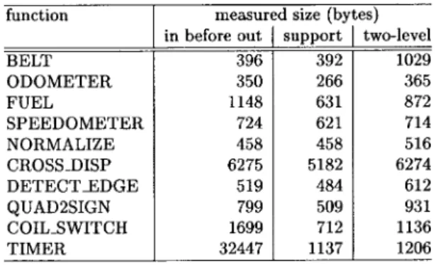
TABLE I
RESULTS OF THECOST/PERFORMANCEESTIMATIONPROCEDURE
TABLE II
EFFECT OFDIFFERENTTESTVARIABLEORDERINGS
experiment with tradeoffs, e.g., between scheduling policies or different event input mechanisms (polling versus interrupts). Commercial RTOS’s typically do not provide such a flexibility.
V. EXPERIMENTAL RESULTS
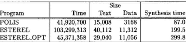
We first report the results of the cost/performance estimation procedure and of the s-graph synthesis procedure applied to a subset of a car dashboard control system. We then compare a manual design and the results of software synthesis for a real industrial example, a shock absorber controller.
In all cases, the numbers are given for a Motorola 68HC11 micro-controller. They are obtained using our estimation pack-age, as well as by actual measurements done on the output of the INTROL C compiler for the 68HC11. The timing columns are given in terms of the maximum number of clock cycles for a single transition of eachCFSM and the code size columns are given in terms of bytes. All the results include both the control and the data part.
A. The Dashboard Controller
The example considered here is a subset of the functionality of a dashboard controller, that implements the computational chain from the wheel and engine speed sensors to the pulse width-modulated outputs controlling the gauges.
Table I summarizes the result of the cost estimation proce-dure, and compares it against an exact measurement of the code size and timing (maximum number of clock cycles), performed by analyzing the compiled object code.
Table II shows the effect of the different orderings in procedure build on the software size. The timing remains