Cooperative Uplink Inter-Cell
Interference (ICI) Mitigation in 5G
Networks
Pitakandage Tinith Asanga Pitakanda
A thesis submitted to the University of Hertfordshire in partial fulfilment of
the requirements for the degree of Doctor of philosophy
The programme of research was carried out in the Science and Technology
Research Institute (STRI), School of Engineering and Technology,
University of Hertfordshire,
United Kingdom.
ABSTRACT
In order to support the new paradigm shift in fifth generation (5G) mobile communication,
radically different network architectures, associated technologies and network operation
algorithms, need to be developed compared to existing fourth generation (4G) cellular
solutions. The evolution toward 5G mobile networks will be characterized by an increasing
number of wireless devices, increasing device and service complexity, and the requirement to
access mobile services ubiquitously.
To realise the dramatic increase in data rates in particular, research is focused on improving
the capacity of current, Long Term Evolution (LTE)-based, 4G network standards, before
radical changes are exploited which could include acquiring additional spectrum. The LTE
network has a reuse factor of one; hence neighbouring cells/sectors use the same spectrum,
therefore making the cell-edge users vulnerable to heavy inter cell interference in addition to
the other factors such as fading and path-loss. In this direction, this thesis focuses on
improving the performance of cell-edge users in LTE and LTE-Advanced networks by
initially implementing a new Coordinated Multi-Point (CoMP) technique to support future
5G networks using smart antennas to mitigate cell-edge user interference in uplink.
Successively a novel cooperative uplink inter-cell interference mitigation algorithm based on
joint reception at the base station using receiver adaptive beamforming is investigated.
Subsequently interference mitigation in a heterogeneous environment for inter
Device-to-Device (D2D) communication underlaying cellular network is investigated as the enabling
technology for maximising resource block (RB) utilisation in emerging 5G networks. The
proximity of users in a network, achieving higher data rates with maximum RB utilisation (as
the technology reuses the cellular RB simultaneously), while taking some load off the
been explored. Simulation results show that the proximity and transmission power of D2D
transmission yields high performance gains for D2D receivers, which was demonstrated to be
better than that of cellular UEs with better channel conditions or in close proximity to the
eNodeB in the network. It is finally demonstrated that the application, as an extension to the
above, of a novel receiver beamforming technique to reduce interference from D2D users,
can further enhance network performance.
To be able to develop the aforementioned technologies and evaluate the performance of new
algorithms in emerging network scenarios, a beyond the-state-of-the-art LTE
system-level-simulator (SLS) was implemented. The new system-level-simulator includes Input
Multiple-Output (MIMO) antenna functionalities, comprehensive channel models (such as Wireless
World initiative New Radio II i.e. WINNER II) and adaptive modulation and coding schemes
ACKNOWLEDGEMENTS
I owe my deepest gratitude to my supervisor Dr. Pandelis Kourtessis for giving me this
opportunity and believing in me all the way through providing guidance and support. Any
attempt at any level cannot be satisfactorily completed without the support and guidance of
him. I would also like to thank my supervisor Prof. John M. Senior for his constant support
and motivation that has encouraged me.
Secondly I would like to express my immense gratitude to Dr. Milos Milosavljevic who is not
only a supervisor but an excellent mentor and a friend who was there for me even in busy
times providing help and support to achieve my goals during my research.
This is also a great opportunity to thank my friends Dr. Ahmed Amate, Dr Xiaojun Zhai, Dr.
Wansu Lim, Dr. Efstratios Sofianos and all my colleagues in D437 for establishing a friendly
working environment and also for giving me valuable advice.
At last but not least, I would like to thank my parents, my sister, Sachi, my housemates and
all my friends and family who were there for me, supporting me in easy and hard times
TABLE OF CONTENTS
ABSTRACT ... ii
ACKNOWLEDGEMENTS ... iv
TABLE OF CONTENTS ... v
LIST OF FIGURES ... viii
LIST OF TABLES ... xi GLOSSARY ... xii DECLARATION ... xv 1. Introduction ... 1 1.1 Mobile Communication... 1 1.1.1 4G Deployment ... 4
1.1.2 Network Performance and Limitations of Current 4G Networks ... 5
1.2 The use of Cooperative Inter-cell Interference Mitigation in 4G Networks and Beyond ... 7
1.2.1 Work towards the Development of Future Generation Networks ... 8
1.3 Research Motivation ... 10
1.4 Research Contributions ... 12
1.5 Thesis Outline ... 14
2. Cooperative Uplink Inter-cell Interference Mitigation towards Realisation of Future Generation 5G Network ... 15
2.1 Introduction ... 15
2.2 Developments of Legacy Cellular Networks and Advances towards 5G ... 15
2.3 Requirements and System Architecture of 4G Networks ... 18
2.3.1 Long Term Evolution (LTE Rel. 8 and 9) ... 18
2.3.2 LTE-Advanced (Rel. 10) Requirements ... 24
2.4 Interference Avoidance and Cancellation ... 26
2.4.1 Coordinated Multi-Point (CoMP) for Interference Mitigation ... 28
2.4.2 Smart Antennas and Beamforming ... 31
2.5 Architectural Developments and Research Initiatives in 5G ... 39
2.6 Summary ... 46
3. State-of-the-art System Level Simulator for Cellular Networks ... 48
3.1 Introduction ... 48
3.2 Link to System Level Modelling ... 49
3.2.1 Link Quality Measurement in System Level Simulator Model ... 53
3.2.2 Network Architecture and Cell Layout ... 55
3.3 Channel Modelling ... 61
3.4 Beamforming and Generating Beam Patterns ... 63
3.5 Transmission Modes in LTE and LTE-A Uplink... 69
3.6 Resource Allocation Algorithms ... 71
3.7 Performance Evaluation ... 75
3.8 Summary ... 80
4. Smart Antennas and Receiver Beamforming for Future Generation Networks ... 83
4.1 Introduction ... 83
4.2 Motivation for Uplink CoMP and Interference Mitigation/ Cancellation ... 84
4.2.1 Current Advances in Uplink CoMP Techniques ... 87
4.3 Novel Adaptive Antenna System for Interference Mitigation in Uplink ... 90
4.4 Methodology and Simulation Investigations ... 95
4.5 Summary ... 108
5. Joint Processing / Reception using Receiver Beamforming in Heterogeneous Network... 110
5.1 Introduction ... 110
5.2 Interference Mitigation using Joint Reception and Coordinated Scheduling ... 111
5.3 Modelling and Evaluation of Proposed Algorithms ... 114
5.4 Performance gains of CS/ BF and Joint Reception with Smart Antennas ... 122
5.5 Joint Processing/ Reception in Small-Cell Environment ... 129
5.6 Summary ... 134
6. D2D Underlying Cellular Networks in a HetNet Environment ... 136
6.1 Introduction ... 136
6.2 Modelling of D2D UEs in SLS ... 137
6.4 Performance Gains of D2D Communication Underlaying Cellular Network
Enhanced by Receiver Beamforming ... 144
6.5 Summary ... 152
7. Research Summary and Future Work ... 154
7.1 Introduction ... 154
7.2 Thesis Summary and Outcomes ... 157
7.3 Future Work ... 162
LIST OF FIGURES
Figure 1-1: 15 Years of Information and communications Technology (ICT) growth (2000 to
2015) [2]... 2
Figure 1-2: Uplink + Downlink monthly traffic growth compared to voice services [1] ... 3
Figure 1-3: Map of 4G-LTE deployment [9] ... 4
Figure 1-4: 5G Networks and services vision [46] ... 8
Figure 2-1: Technology and standards evolution towards 5G [61] ... 17
Figure 2-2: LTE network architecture [62] ... 20
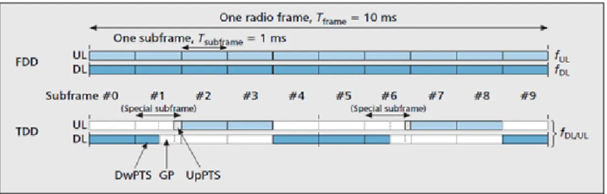
Figure 2-3: LTE frame structure [4] ... 22
Figure 2-4: Resource grid structure for LTE [64] ... 23
Figure 2-5: Intra and inter-eNodeB inter-cell interference [75] ... 26
Figure 2-6: CoMP architecture for JP and CS/CB transmission [31] ... 29
Figure 2-7: Joint processing techniques [82] ... 29
Figure 2-8: Co-ordinated beamforming/ scheduling [31] ... 30
Figure 2-9: Beamforming smart antenna system ... 32
Figure 2-10: Switched beam smart antenna system [67] ... 33
Figure 2-11: Direct signal and interfering and/or multipath signals from interferers ... 33
Figure 2-12: Adaptive smart antenna array ... 34
Figure 2-13: D2D Communication: Technology and Prospect [92] ... 36
Figure 2-14: D2D communication with and without network assist [100] ... 37
Figure 2-15: 5G Roadmap [46] ... 40
Figure 2-16: High-level topological view of 5G network architecture [110] ... 41
Figure 2-17: METIS 5G scenarios [40] ... 42
Figure 2-18: CRAN network architecture [115] ... 43
Figure 3-1: General Layers of Link-Level and System-Level Simulators [123] ... 50
Figure 3-2: BLER curve generated from LLS for 5000 sub-frames ... 51
Figure 3-3: Macroscopic path-loss for an UE and an eNodeB with 30 degrees azimuth in a ROI ... 53
Figure 3-4: Correlated shadow fading map for 7 eNodeB sites (Tier 1 network) ... 54
Figure 3-5: Cell layout consisting 3 hexagonal sectors ... 55
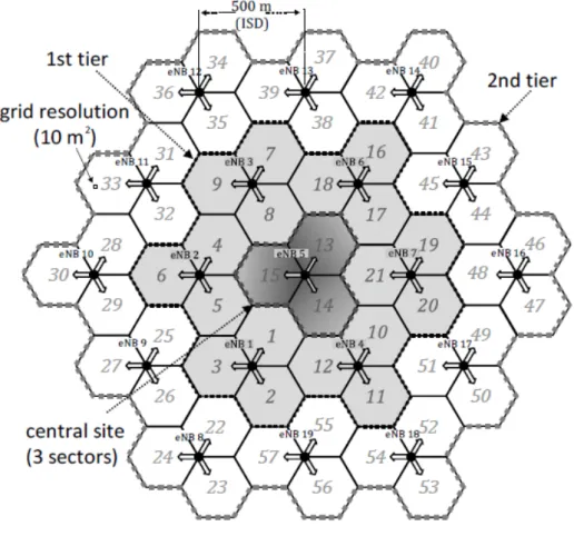
Figure 3-6: Typical 2-tier macro-cell layout with 500m ISD ... 56
Figure 3-8: Cell-layout used for the performance investigation (Target sector: sector 13 where
simulation results were obtained) ... 58
Figure 3-9: Random UE generation in a single tier cell-layout ... 59
Figure 3-10: Antenna beam pattern for positions inside 120dB and 80dB ... 64
Figure 3-11: Antenna beam pattern inside the range of < 80dB ... 65
Figure 3-12: Coverage consistency check for the fixed beams ... 66
Figure 3-13: Single tier network with fixed beam antenna configuration ... 68
Figure 3-14: Transmission mode comparison between SISO and CLSM with 2 x 2 and 4 x 4 antenna configurations for different UE speeds... 71
Figure 3-15: Normalized throughput CDF with the two scheduling algorithms for UEs in target sector ... 74
Figure 3-16: Single tier cell layout with the target sector (13) ... 75
Figure 3-17: Uplink normalized throughput for different bandwidths ... 76
Figure 3-18: Coverage% performance ... 77
Figure 3-19: Interference % towards neighbouring UEs ... 79
Figure 4-1: (a) FiWi system architecture with (b) the proposed receiver beamforming technique ... 91
Figure 4-2: Digital beamforming receiver (receiver beamformer) [173] ... 93
Figure 4-3: Cell layout setup consists of 7 eNodeBs ... 96
Figure 4-4: Cooperating cells and conflicting boarder between sector 13 and 21... 97
Figure 4-5: Smart antenna system with receiver beamforming (a) 2 elements (b) 4 elements ... 103
Figure 4-6: Cell coverage with and without beamforming for different antenna configuration ... 104
Figure 4-7: Throughput for different beamforming techniques for 1×2 antenna configuration ... 105
Figure 4-8: Throughput with and without receiver beamforming for different number of antenna elements ... 106
Figure 5-1: Normal/fixed direction of the antenna beams for the non-adaptive antennas in eNodeBs ... 112
Figure 5-2: Single tier cell layout consisting of 7 sites (with 3 sectors each) with an ISD of 500m ... 114
Figure 5-3: FiWi system architecture with cooperative scheduling/beamforming at TTI 1 .. 115
Figure 5-5: System architecture with joint reception with the assistance of receiver adaptive
beamforming in TTI 1 ... 119
Figure 5-6: System architecture with joint reception with the assistance of receiver adaptive beamforming in TTI 2 ... 120
Figure 5-7: Normalized throughput for 1x2 antenna configurations ... 124
Figure 5-8: Normalized throughput for 2x4 antenna configurations ... 125
Figure 5-9: Normalized throughput for CS/BF compared to joint reception... 126
Figure 5-10: Spectral efficiency for CS/BF and JR with receiver beamforming compared to non-CS/BF reception ... 127
Figure 5-11: Normalized throughput for CS/BF compared to joint reception in high-speed UEs ... 128
Figure 5-12: Heterogeneous deployment with uplink CoMP ... 129
Figure 5-13: JR in Heterogeneous Network (1 small-cell) ... 131
Figure 5-14: JR in Heterogeneous Network (3 small-cells) ... 132
Figure 5-15: JR in Heterogeneous Network Comparison ... 133
Figure 6-1: Cell layout consisting of 7 sites (with 3 sectors each) ... 138
Figure 6-2: D2D UEs in a cellular environment ... 139
Figure 6-3: Path-loss of the target sector eNodeB with azimuth of 30 degrees and the D2D UE in the ROI ... 139
Figure 6-4: Two main interference scenarios in the D2D communication [104] ... 142
Figure 6-5: Intra and Inter-cell D2D communication in a heterogeneous network ... 145
Figure 6-6: Pseudo code for the mode selection for UEs ... 146
Figure 6-7: Impact of D2D TX power to the cellular UEs in an intra-cell D2D scenario ... 148
Figure 6-8: Normalized CDF of UEs goodput distribution with and without D2D transmission ... 149
Figure 6-9: Inter-cell D2D communication with compared to no D2D and D2D with receiver beamforming ... 151
Figure 7-1: High level representation of CRAN network [199] ... 165
Figure 7-2: Joint reception in CRAN environment... 165
Figure 7-3: D2D communication in a CRAN environment ... 166
LIST OF TABLES
Table 2-1: Major system requirements for LTE Rel.8 [14] ... 19
Table 2-2: System performance requirements for LTE-Advanced [80] ... 25
Table 3-1: Simulation parameters ... 60
Table 3-2: Coverage results and antenna elements ... 78
Table 3-3: Interference towards neighbouring UEs ... 80
Table 4-1: Comparison of available uplink CoMP and interference reduction / cancellation techniques ... 89
Table 4-2: Receiver beam steering conditions for cooperating cells in target sector ... 101
Table 4-3: Simulation parameters ... 102
Table 4-4: Spectral efficiency comparison ... 107
Table 5-1: Coordinated scheduling with receiver beamforming conditions for cooperating cells in target sector ... 117
Table 5-2: Simulation parameters ... 122
Table 5-3: Base station configurations in the heterogeneous network ... 131
GLOSSARY
1G First generation
2G Second generation
3G Third generation
3GPP 3rd Generation Partnership Project
4G Fourth generation
5G Fifth generation
ADC Analogue to Digital Conversion
AWGN Additive white Gaussian noise
BBU Baseband unit
BS Base station
CAPEX Capital expenditure
CDF Cumulative distribution function
CoBF Coordinated beamforming
CoMP Coordinated multipoint
CoSH Coordinated scheduling
CR Cognitive Radio
D2D Device-to-Device
DL Downlink
DSP Digital Signal Processing
EPC Evolved packet core
HDTV High-definition television
HetNet Heterogeneous network
IMT-A International mobile telecommunications Advance
IP Internet protocol
IoT Internet of Things
ITU International telecommunication union
ISD Inter-site distance
JP Joint processing
LTE Long term evolution
LPM Link performance model
LQM Link quality model
LTE-A Long-term evolution Advanced
M2M Machine to Machine
OFDM Orthogonal frequency-division multiplexing
OPEX Operational expenditure
QoE Quality of Experience
QoS Quality of service
RAN Radio access network
RAT Radio access technology
RRH Remote Radio Head
ROI Region of interest
SE Spectral efficiency
SLS System-level simulator
SIC Self-interference cancellation
SC-FDMA Single carrierfrequency-division multiple access
UL Uplink
WiFi Wireless fidelity
WiMAX Worldwide interoperability for microwave access
WINNER Wireless world initiative new radio
WLAN Wireless local area network
WMAN Wireless metropolitan area network
WPAN Wireless personal area network
DECLARATION
The following papers are either under review or already published, and parts of the materials
are included in this thesis:
• (Invited) T. Pitakandage, M. Milosavljevic, P. Kourtessis, and J. M. Senior,
"Cooperative 5G switched and adaptive receiver beamforming for fibre wireless
networks," in 2014 16th International Conference on Transparent Optical Networks
(ICTON) 2014, pp. 1-4.
• (Invited) T. Pitakandage, M. Milosavljevic, P. Kourtessis, and J. M. Senior,
"Cooperative uplink inter-Cell interference (ICI) mitigation in 5G Fibre Wireless
(FiWi) networks," in 2015 17th International Conference on Transparent Optical
Chapter 1
1.
Introduction
1.1
Mobile Communication
In recent years, wireless communication networks have developed rapidly and the explosion
of mobile services such as Internet of Things (IoT) with numerous low-cost Machine Type
Communications (MTC) devices, intelligent wearable devices, vehicular sensors and
environmental sensors etc has greatly increased the demand for higher wireless data rates to
be delivered over cellular networks [1, 2]. It has been reported that in the near future, i.e. year
2020, some of the prime objectives or demands that need to be addressed are increased
capacity, improved data rates, decreased latency, and better Quality of Service (QoS) [3].
Fifth Generation (5G) mobile is expected to be in operation around 2020, aiming to change
the world by providing solutions to increasing internet data traffic which has driven the
capacity demands for currently deployed Third Generation (3G) and Fourth Generation (4G)
wireless technologies [4]. Societal development will lead to changes in the way mobile and
wireless communication systems are used. Essential services such as e-banking, e-learning,
and e-health will continue to proliferate and become more mobile [5]. On-demand
information and entertainment (e.g., in the form of augmented reality) will progressively be
delivered over mobile and wireless communication systems. These developments will lead to
an avalanche of mobile and wireless traffic volume, predicted to increase a thousand-fold
over the next decade [6, 7].
In a recent International Telecommunication Union (ITU) survey, it is highlighted that third
generation (3G) mobile-broadband coverage is extending rapidly by covering 7.40 billion
2 According to ERICSSON [1], advanced mobile technology will be globally ubiquitous by
2020 with 70 percent of people using smartphones and 90 percent covered by mobile
broadband networks. Smartphones make up the majority of mobile broadband devices today
and subscriptions are expected to have more than doubled by 2020, reaching 6.10 billion [1,
8].
The number of mobile broadband subscriptions is growing globally by around 30 percent
year-on-year, increasing by approximately 150 million in the first quarter (Q1) of 2015 alone
[1]. Long Term Evolution (LTE) continues to grow strongly and has reached around 600
million subscriptions, with approximately 105 million additions in Q1 of 2015 as shown in
Figure 1-2 [1, 2]. Wideband Code Division Multiple Access/ Global System for Mobile
(WCDMA/GSM) added around 60 million during Q1. The majority of 3G/4G subscriptions
have access to Enhanced Data rates for GSM (GSM/EDGE) as a fall-back, although
GSM/EDGE-only subscriptions declined by 30 million [8].
Figure 1-1: 15 Years of Information and communications Technology (ICT) growth
New network functionalities and service capabilities are being implemented for both data and
voice. These include improvements to both downlink and uplink speeds and new ways to
efficiently deliver content at a certain quality level, e.g. LTE Broadcast. Improved voice
quality and new, richer communications services like mobile HD voice (HD voice services
using Adaptive Multi Rate Wideband technology (W-AMR)), Voice over LTE (VoLTE),
video calling and enriched messaging are enabled by IP-based networks. Furthermore, with Figure 1-2: Uplink + Downlink monthly traffic growth compared to voice
4 native Wireless-Fidelity (Wi-Fi) calling functionality now available on smartphones, users
can be offered operator voice and communication services (SIM-based) over Wi-Fi.
1.1.1 4G Deployment
The following Figure 1-3 depicts the global coverage of 4G-LTE deployment in recent years as published in [9].
Figure 1-3: Map of 4G-LTE deployment [9]
According to a survey by Global mobile Suppliers Association (GSA) (an association with
members such as Qualcomm, Ericson, Huawei, etc.) and the GSMA intelligence data, there
were 352 operators with live commercial 4G-LTE networks globally as of the end of January
2015, with more than half of the world’s mobile markets covered by at least one LTE
operator [9, 10]. Most of the LTE operators with more than 30% of the total (108) are in
Europe, followed by Asia Pacific (66), Latin America (55) and North America (47). Even
though Asia Pacific region accounts for only one in six of the world’s LTE operators, it
provides almost half (47%) of LTE connections, largely due to substantial LTE bases in
South Korea, Japan and China. Compared to the 14% of Europe connections, North America
of 2015 more than 10% of connections globally will be on LTE, with this share rising to more
than three in every ten connections by 2020 [9-11].
1.1.2 Network Performance and Limitations of Current 4G Networks
Following the successful standardisation of High Speed Packet Access (HSPA), the 3rd
Generation Partnership Project (3GPP) has specified the Universal Mobile
Telecommunications System (UMTS) Terrestrial Radio-Access Network or UTRAN — LTE
to meet the above mentioned increasing performance requirements of mobile broadband [12].
The peak throughput is 300Mbps in Downlink (DL) and 75Mbps in Uplink (UL), 2-3 time
higher spectrum efficiency than Rel. 6 HSPA, very low latency around 5ms in Radio Access
Network (RAN) and 100ms for connection setup time [13-15].
LTE offers extensive support for spectrum flexibility, supports both Frequency-Division
Duplex (FDD) and Time-Division Duplex (TDD) and targets a smooth evolution from earlier
3GPP systems such as Wideband Code Division Multiple Access /High Speed Packet Access
as well as 3rd Generation Partnership Project 2 systems such as CDMA2000 [3, 16, 17].
LTE downlink is implemented based on Orthogonal Frequency-Division Multiple Access
(OFDMA) [18] and the uplink is based on the Single-Carrier Frequency Division
Multiplexing Access (SC-FDMA) scheme where it has a low peak to average power ratio
compared to OFDMA [19, 20]. Hence SC-FDMA transmission scheme was selected since it
provides more energy efficiency from the User Equipment (UE) processing power
requirement perspective [21].
Long Term Evolution Advanced (LTE-Advanced) known as Rel. 10 is an evolution of Rel. 8,
therefore distinctive performance gains up to 1Gbps in downlink and 500Mbps in uplink peak
6 Multiple-Input-Multiple-Output (MIMO). LTE-Advanced should satisfy all the relevant
requirements for LTE Rel. 8 [22, 23]. Secondly it should be fully backward compatible with
Rel. 8. Therefore, a set of UEs for LTE-Advanced must be able to access Rel. 8 networks,
and LTE-Advanced networks must be able to support Rel. 8 UEs. LTE-Advanced also shall
meet or exceed the International Mobile Telecommunications Advanced (IMT-Advanced)
requirements within the ITU-R time plan [24, 25]. The target peak data rate for the downlink
was set to 1Gbps and the target peak data rate for the uplink was set to 500 Mbps [25].
Furthermore, new techniques like MIMO [26], carrier aggregation, coordinated multipoint
(CoMP) and relaying were introduced in order to achieve the required capacity gain, along
with more reliable communication [25].
LTE and LTE-Advanced are an Orthogonal Frequency Division Multiplexing (OFDM) based
network utilize a frequency re-use of one (denoted by N = 1) [27]. A frequency re-use of N =
1 implies that the base stations in cells transmit on all available time-frequency resource
blocks (RBs) simultaneously. However the resulting interference limited system for N = 1
deployment will not achieve the full potential capacity particularly for users at the cell edge.
This is due to the high inter-cell interference, since all the cells use the same spectrum [28].
Therefore it becomes one of the main performance limitations of the 4G LTE network as the
cell edge performance is compromised. Over the years the importance of inter-cell
interference, has been recognised, and various techniques used from the days of GSM to
mitigate its effects. Lot of research has been done in this area especially in downlink with the
introduction of techniques like CoMP.
Multi-path fading is another limitation where obstacles in the surrounding environment
attenuate the propagated signal, leading to flawed detection of the received signal [29]. Due
budget will impose the need for smaller cell sizes or better interference mitigation techniques
[30, 31].
In this direction scarcity of radio spectrum (which is finite and expensive) is also a major
issue with wireless communication in general since it leads to inefficient spectrum usage.
This requirement is driven by the need to meet targeted higher data throughputs for users not
only near the base stations, but also at cell edge. This limits the LTE from providing the
increasing high data rate requirements and quality of service (QoS). The trend of increasing
demand for high QoS at the user terminal (UEs), coupled with the shortage of wireless
spectrum, requires more advanced wireless communication techniques such as CoMP, joint
reception, smart antennas to provide solutions, specially to mitigate inter cell interference to
increase the cell edge throughput [32].
1.2
The use of Cooperative Inter-cell Interference Mitigation in 4G
Networks and Beyond
Since the standardization and deployment process for the 4G technologies (LTE,
LTE-Advanced) are mostly established, it is time for the research community to explore and
research on what is likely to come next [33, 34]. It is anticipated that trillions of wireless
nodes in IoT with diversified applications and services will be available in 5G wireless
communication systems. These devices, however, may not be handled efficiently by the
current wireless communication networks, which were not designed for frequent small data
packets and simultaneous massive access [35, 36]. In this direction 5G studies are gaining
more momentum worldwide, in an attempt to provide solutions for the exponential increase
of mobile data traffic by 2020 [37, 38]. There are several projects and research initiatives
8 METIS II [40, 41], 5GNOW [42], Combo [43], MOTO [44], MCN and iJOIN [45], etc. The
following diagram (Figure 1-4) illustrates the 5G networks and services vison.
Figure 1-4: 5G Networks and services vision [46]
As illustrated in Figure 1-4 in order to meet the expected high throughput targets, small cells
will be pushed further leading to Ultra Dense Networks (UDN). 5G will also introduce new
radio area network paradigms such as Device to Device (D2D), Moving Networks (MN) and
many more novel technologies as described in the next section.
1.2.1 Work towards the Development of Future Generation Networks
3GPP has been working on various aspects in the framework of 4G LTE-Advanced to
enhance the spectrum utilisation and to provide the required bandwidth requirements. Mainly
it introduced features including carrier aggregation; enhanced Inter-Cell Interference
Coordination (eICIC), Co-ordinated MultiPoint (CoMP), advanced Heterogeneous Network
(HetNet) capabilities, Massive MIMO and Device to Device communication as key enablers
increase user data rates for all users. A HetNet is an attractive means of expanding mobile
network capacity which is composed of multiple radio access technologies, architectures,
transmission solutions, and base stations of varying transmission power. By enabling the
hyper-dense HetNets (small-cells) and by integrating macro-cells with Pico and Femto-cells
the anticipated 1000x capacity increase could be achieved. But this is only possible with
advanced interference management techniques such as CoMP and Further-enhanced
Inter-Cell Interference Coordination (FeICIC/IC) [47, 48]. These interference mitigation
techniques are important for interference coordination between small cells, on the network
side and also to cancel interference on common channels, on the device side.
Enhanced receivers play a crucial role in further improving LTE-Advanced. Devices that
cancel inter-cell interference on both control and data channels provide more capacity and
better data rates, particularly at cell-edges which will increase the user experience. Managing
and cancelling interference in dense small cell deployments is even more beneficial to
increase the overall performance [49, 50].
Extending LTE-Advanced to the unlicensed spectrum will benefit both 3G/4G operators and
users where the operators can leverage on both licensed and unlicensed spectrum using a
unified network to expand data capacity. Nevertheless users get seamless broadband
experience and robust connectivity because of the fixed connection to the licensed spectrum.
Cognitive Radio (CR) enables secondary users (unlicensed users of a spectrum) to sense/find
and utilise the spectrum when it is not in use by the primary users (licensed users) with
interference control for transmission between the respective users [51]. D2D communications
is a peer to peer link which does not use the cellular network infrastructure, but enables LTE
based devices to communicate directly with one another when they are in close proximity.
10 the cellular network itself, thereby avoiding problems with overloading the network. When
the devices are in close proximity, by enabling D2D several benefits such as higher data rates
to remote users from the cellular infrastructure, reliable communication to communicate
locally if a network failure occurred, and power savings to users in various applications can
be achieved [52]. These technologies introduced for 4G is envisioned for implementation in
the LTE-Advanced network even though they are strong candidate technologies for the 5G
networks. However some of the technologies mentioned come with some technical
challenges that require solutions before their full implementation in future networks.
1.3
Research Motivation
To explore the full 4G potentials the aforementioned limitations should be resolved by
appropriate research. As mentioned in the earlier section one of the critical challenges that the
mobile industry will face is the inter-cell interference due to the expected significant cell
densification. Research in this direction can be used to implement and amend new techniques
or as a reference point for vendors and service providers to improve and develop their
individual services.
Cell-edge interference in addition to fading and path-loss which is commonly experienced in
wireless communications is a major factor limiting 4G networks to achieve its full potential.
Therefore major research has been produced in recent five to six years on developing
inter-cell interference coordination using CoMP algorithms primarily in downlink to improve the
cell-edge performance of UEs in order to be able to support the required 10-fold increase in
spectral efficiency on the roadmap from 4G to 5G. In 2010, EASY-C [53] a major project,
provided the principal proof-of-concept which gained significant experience in the
implementation and application of the CoMP concepts to improve cell-edge user data rate
techniques that enable dynamic coordination or transmission and reception with multiple
geographically separated eNodeBs. Its aim is to enhance the overall system performance by
utilising the resources more effectively and improve the end user service quality. Yet there
are limited references on similar work taking place in uplink cell-edge interference
mitigation. However in the present day, the demand for uplink communication has become a
critical factor, across networks and technologies [50, 54]. It can be seen that the user
behaviour in uplink is equally important as the downlink. Even in the optical domain,
research is carried out to achieve higher symmetric data rates, compared to the asymmetric
data rates which was well-known few years back. A higher transmission rate for uplink has
attracted the attention of main research communities and telecoms providers’ worldwide [36,
39, 42, 55]. In order to support this paradigm shift in mobile communication, radically new
solutions for the air interface need to be developed. Uplink Inter-cell interference could be
reduced using CoMP techniques, similar to those in downlink, and advanced receivers with
smart antennas since it is one of the most critical factors which reduce the spectral efficiency
of the system.
In view of the aforementioned analysis, this thesis proposes a novel uplink CoMP interface
mitigation technique for future mobile networks. The novel technique using smart antennas
can also be used to enhance the joint reception in a heterogeneous environment. Later part of
the thesis will investigate its performance in a D2D environment. This technology enables the
performance of the antenna to be altered to provide the performance that may be required to
undertake performance under specific or changing conditions. The smart antennas include
signal processing capability that can perform tasks such as analysis of the direction of arrival
(DoA) or angle of arrival (AoA). There are two types of smart antennas which is switched
beam and adaptive arrays. The switched beam smart antennas are designed to have several
12 to any direction to allow for the maximum signal to be received and to nullify or mitigate the
interference from interfering UEs. These techniques can be also used with conjunction to
joint reception to increase the spectrum utilisation improvement for users’ further away
(cell-edge) from the eNodeB, or with relatively poor channel condition.
Moving towards the 5G networks, Device-to-Device (D2D) communications underlying
cellular networks have been recently proposed as a promising technology to satisfy the
increasing demand for local data traffic, and also to provide better user experience in the next
generation 5G cellular networks. Another main enhancement for future 5G wireless systems
is integrating the standard coverage of traditional macro-cells with small cells of reduced
dimensions. By using the D2D technology significant gains can be achieved with close
distance transmission between user equipment without traditionally going through a base
station. Most existing literature is limited to studying D2D communication for UEs in the
same cell (inside the Macro-cell). Therefore the later parts of this research study investigates
on inter-site D2D communication. To that extent, this work is tackling the interference issues
in uplink direction, and focused on investigating on technologies to improve the recent 4G
networks and endorse their suitability as candidate technologies for the future 5G network
implementations.
1.4
Research Contributions
The major contributions of this thesis are highlighted as follows:
A comprehensive state-of-the-art uplink system-level model was developed using
MATLAB programming to evaluate the performance of proposed algorithms for the
next-generation 4G/ 5G networks. The detail of the simulation environments (rural,
transmission modes and scheduling algorithms of the LTE network were evaluated to
identify the most efficient parameters for the research to follow.
To provide direct coverage to areas where capacity is needed, an inter-cell
interference mitigation method based on adaptive smart-antenna was proposed.
Adaptive antenna in the proposed technique is complemented by the presence of
switched antenna beamforming, applicable to selective cluster UEs saving on
processing power at the evolved Node B (eNodeB). The performance of the cell-edge
users was then illustrated, and a novel CoMP algorithm was proposed, which was
shown to improve the performance of users in the network by reducing the effect of
interference on the cell-edge users.
Multi-site connectivity using joint reception with receiver beamforming was then
implemented. The model was used to illustrate the spectrum utilisation improvement
with joint reception for users’ further away (cell-edge) from the eNodeB, or with
relatively poor channel condition. Joint reception in heterogeneous networks was then
taken into consideration which entails the low power RRUs to provide better uplink
reception with reduced interference adjustment of UE transmitter power depending on
the SINR feedback of the UEs in its existing cell. This was implemented to maintain a
good performance between the eNodeBs and cell-edge users in the network even with
the simultaneous sharing of resources between the network entities.
D2D communication in a heterogeneous environment (small-cell) was then
investigated. This differed from the current use of the scheme which is limited to UEs
in the same cell to increase cell capacity and improve cellular user experience in a
macro-cell environment. In this case, D2D communication was implemented in a
14 This has shown further improvement in the cell throughput compared to standard and
joint reception techniques either presented as a result of the research conducted in this
thesis or elsewhere in literature.
1.5
Thesis Outline
Chapter 2 of the thesis provides a thorough literature review of 4th and 5th generation cellular networks including technologies such as smart adaptive antenna systems, CoMP techniques,
small cells and D2D communication. Chapter 3 starts with a detailed description of the
developed system level simulator which will give an introduction to the MATLAB based
state-of-the-art uplink system level simulator model implemented for this research study.
Chapter 4 will illustrate the inter-cell interference mitigation method based on adaptive
smart-antennas. It is concluded by presenting the cell-edge performance enhancements by
implementing the proposed novel CoMP receiver beamforming technique. This is followed
by Chapter 5 which investigates on the joint reception/processing using the proposed receiver
beamforming technique. It provides detail in how multi-site connectivity enhances the
cell-edge throughput and spectral efficiency. Chapter 6 discuses and evaluates the D2D
communication in a HetNet environment. The designed architecture is progressively
enhanced to evaluate the performance of D2D users in an inter-cell/site environment. Finally,
Chapter 7 summarises the work conducted throughout this research programme and
Chapter 2
2.
Cooperative Uplink Inter-cell Interference Mitigation towards
Realisation of Future Generation 5G Network
2.1
Introduction
This chapter highlights the most up to date literature review on the topologies, technological
advances and application scenarios of 4G and emerging 5G cellular networks with an
emphasis on the solutions for interference mitigation. The explored topologies focus mainly
on LTE and LTE-Advanced as the predominant 4G network, discussing their envisaged
limitations towards the implementation of future 5G networks, with respect to primarily cell
edge interference cancellation performance but also heterogeneous environment (small-cell),
where this research focuses on providing solutions. Technologies such as smart adaptive
antenna systems, Co-ordinated Multi Point (CoMP) techniques, small-cells and
Device-to-Device (D2D) communication are discussed as projected techniques/technologies and
developments towards efficient radio resource utilisation to achieve the future 5G capacity
demand and quality of service.
2.2
Developments of Legacy Cellular Networks and Advances
towards 5G
The first generation (1G) of cellular networks fulfilled basic mobile voice services (analogue
phone calls). The second generation (2G) networks introduced capacity, security and
coverage. The most adopted 2G wireless standard is known as Global Systems for Mobile
Communications (GSM). GSM introduced data services for mobile with a better coverage
16 picture messages and multi-media messages (MMS). All text messages sent over 2G are
digitally encrypted, allowing for the transfer of data in such a way that only the intended
receiver can receive and read it.
This was followed by the third generation (3G), where the specifications called for 144Kbps
while the user is on the move in an automobile or train, 384Kbps for pedestrians, and up to
2Mbps for stationary users. This was a big step up from 2G bandwidths which uses 8 to
13Kbps per channel to transport voice signals for the GSM standard [56]. The ITU prescribed
performance targets for fourth generation (4G) networks such as better data rates (300Mbps
using LTE and up to 1Gbps using LTE-A), lower latency (5ms), accessibility, availability and
mobility. These targets were matched with the emergence of LTE under the auspices of
3GPP. 4G networks provides access to a wide range of telecommunication services, including
advanced mobile services, supported by mobile and fixed networks, which are increasingly
packet based, along with a support for low to high mobility applications and higher data rates,
in accordance with service demands in multiuser environment.
The fifth generation (5G) should be a more intelligent and robust technology that has flexible
infrastructure capable of handling the ever-increasing demand for data and providing
connectivity for future technologies like the Internet of Things (IoT). Examples of these
capabilities include very high achievable data rates over 1Gbps (10Gbps in specific scenarios
such as indoor and dense outdoor environments), very low latency of less than or equal to
1ms (end-to-end round trip delay), ultra-high reliability, and the possibility to handle extreme
device densities [57, 58]. Some of the key technology components include extension to
higher frequency bands, advanced multi-antenna transmission, data/control separation,
flexible spectrum usage, complementary device-to-device communication and
overview of the cellular network standards evolution and their data rate capabilities are
summarised in Figure 2-1 [61].
As represented in the timeline of Figure 2-1, data traffic in mobile communication systems
has been increasing at an enormous rate with the spread of smartphones and tablets [62]. In
the decade beyond 2020, it will be necessary to support 1000 times higher mobile data
volume per area [6], 1ms end-to-end round trip delay (latency), 90% reduction in network
energy usage together with new wireless broadband communication services [40].
The following subsections provide a general overview of the LTE and LTE-Advanced (4G)
network architectures. Furthermore it concentrates on highlighting theory and technologies
that are relevant to algorithms and performance evaluations carried out in this research. These Figure 2-1: Technology and standards evolution towards 5G [61]
18 include the physical layer design, architectural design and technologies such as CoMP, smart
antennas, joint reception and D2D underlaying cellular networks.
2.3
Requirements and System Architecture of 4G Networks
Over the last few years the demand for accessing the internet using mobile devices has
increased rapidly. To provide the solution for this growing demand the candidate solution
should be able to provide a framework for high mobility broadband services and cell-edge
performance. Following the successful standardization of High Speed Packet Access (HSPA),
the 3GPP specified the Universal Mobile Telecommunications System (UMTS) terrestrial
radio-access network or UTRAN LTE to meet the increasing performance requirements of
mobile broadband mentioned above [12].
At the time of its development and in preparation for its deployment, when compared to
WiMAX (IEEE 802.16 standard) which comes from Institute of Electrical and Electronics
Engineers (IEEE family), LTE has gained more popularity since it provided higher
bandwidth with increased overall system capacity, higher mobility, reduced latency,
improved spectral efficiency and cell-edge performance [63] which is of significance to the
work in this thesis. LTE is an all-IP network that provides seamless mobility and required
QoS for triple-play services and has an added advantage over mobile WiMAX since it uses
the evolution of existing UMTS infrastructure, currently being used by mobile service
providers worldwide [64].
2.3.1 Long Term Evolution (LTE Rel. 8 and 9)
The peak throughput of LTE Rel.8 is 100Mbps (300Mbps for 4x4 MIMO configuration) in
downlink and 50Mbps in uplink, 2-3 time higher spectrum efficiency than Rel. 6 HSPA, very
version for LTE specification, which was completed in March 2009, the LTE standard is now
being developed towards commercialization in various countries [65]. Table 2-1 below
summarizes the major system specifications of LTE Rel.8 provided by ITU [65, 66].
Table 2-1: Major system requirements for LTE Rel.8 [14]
Bandwidth Support of scalable bandwidth (1.4, 3, 5, 10, 20MHz)
Peak data rate DL: 100Mbps UL: 50Mbps
Latency
Transfer delay in RAN 5ms (one-way)
Connection setup delay 100ms
Antenna configuration Spectrum efficiency[bps/Hz]
UL: 1 x 2 UL: 2 x 4 0.8 N/A DL: 2 x 2 DL: 4 x 2 DL: 4 x 4 1.6 1.7 2.7
LTE offers extensive support for spectrum flexibility, both frequency-division duplex (FDD)
and time-division duplex (TDD) and targets a smooth evolution from earlier 3GPP system
such as Wideband Code Division Multiple Access (WCDMA)/ HSPA as well as 3rd
20 The radio access network of LTE consists of only evolved NodeBs (eNodeBs), which are
basically ‘intelligent’ radio base stations. These eNodeBs are capable of allocating radio
resources among its connected user equipment in a distributed manner without the
involvement of any core network elements compared to base transceiver station (BTS) of
previous networks. A typical LTE network architecture is shown in Figure 2-2 [68].
The eNodeBs are connected to each other through the X2 logical interface which facilitates
direct communication between neighbouring cells and to the LTE core network (also referred
to as Evolved Packet Core (EPC) through the S1 interface, which is dedicated to data and
control plane signalling transport. The EPC can be also connected to other 3GPP and
non-3GPP radio-access networks. The EPC consists of a Mobility Management Entity (MME), a
Serving GateWay (S-GW), and a Packet Data Network GateWay (PDN-GW). These core
network elements facilitate proper management of LTE network elements and provide links
S-GW
MME
P-GW
Internet
Cellular link X2 interface S1 interface EPC E -UTRAN eNB UE eNB UE Laptop UE Laptop IPTV/ VoDto other networks. The mobile terminal is denoted as user equipment (UE). When compared
to UTRAN Rel. 6 some functionalities performed by the Radio Network Controller (RNC) in
UTRAN, such as ciphering and header compression, is performed by the eNodeBs in LTE.
Further, handovers between eNodeBs are handled through packet forwarding over the X2
interface rather than by means of a central Automatic Repeat reQuest (ARQ) entity in the
RNC as in UTRAN [12, 65, 68, 69].
Orthogonal Frequency-Division Multiplexing (OFDM), with data transmitted on a large
number of parallel, narrow-band subcarriers in combination with a cyclic prefix , is the core
of the LTE downlink radio transmission [3]. And the transmission is robust to time dispersion
on the radio channel without a requirement to resort to advanced and complex receiver-side
channel equalization [3, 21]. In addition to its advantages for a low-complexity receiver
design, the multicarrier concept enables the operation of LTE in many system bandwidths up
to 20MHz by adapting the number of subcarriers used to the allocated system bandwidth
[21].
In the downlink, above mentioned properties simplifies the receiver baseband processing with
reduced terminal cost and power consumption as a consequence. This is significantly
important considering the wide transmission bandwidths of LTE [3]. The transmitted signal is
organized into sub frames of 1ms duration, each consisting of 14 or 12 OFDM symbols,
depending on whether normal or extended cyclic prefix (CP) is used. Ten sub frames form a
radio frame [3]. The subcarrier spacing of the LTE is 15 kHz with two CP lengths, in both the
up and downlink. One of the most important characteristics of the LTE is its ability to utilize
22 As illustrated, out of the two frame structure types of the LTE (TDD and FDD), the FDD is
optimised to coexist with the 3.84Mb/s UMTS system. Therefore it is commonly considered
in most literature. It contains 10 sub-frames with a total of 10ms (each sub-frame having two
slots of 0.5ms), and has similar frame structure for DL and UL with different channels and
signal positions in each case [3].
OFDM supports multi-user access because within a transmission interval, subcarriers can be
allocated to different users [12]. In the downlink it uses OFDM but in uplink, single-carrier
frequency-division multiplexing (SC-FDM) is implemented via Discrete Fourier Transform
spread OFDM (DFT-SOFDM) [21]. This is because higher priority is given to achieving
wider area coverage than achieving higher performance by utilizing the robustness against
multipath interference in a multicarrier approach [17], since SC-FDMA signals have better
peak-to-average power ratio (PAPR) properties compared to an OFDMA signal.
Figure 2-4 illustrates the resource grid structure for LTE uplink. The transmitted signal in
each slot is described by a resource grid where the bandwidth allocated to a UE is in the form
of a resource block (RB). The resource grid comprises of 12 subcarriers and a number of
SC-FDMA symbols which differs for different CP length and system bandwidth. Figure 2-3: LTE frame structure [4]
Figure 2-4: Resource grid structure for LTE [64]
The number of SC-FDMA symbols in a slot depends on the cyclic prefix length (Normal or
extended cyclic prefix) configured by higher layers. Therefore when using normal cyclic
prefix RB consists of 84 resource elements (RE) and when cyclic prefix extended is used it
consist of 72 REs. A single RE can carry a single modulation symbol hence 2 bits when using
QPSK, 4 bits when using 16QAM and 6 bits when using 64QAM [3, 70].
Although the LTE system is far superior to the existing systems in many aspects including
throughput, delay, and spectrum efficiency, the 3GPP worked on further enhancements of
LTE towards Rel. 9 completed in June of 2010 [17]. The main target of LTE Rel. 9 is to
enhance some of the features introduced in Rel.8. Some of these features are Closed
Subscriber Group (CSG) control which is a mechanism to limit cell access rights to only
users belonging to the CSG [71]. Self-Organizing Networks (SON) is another enhancement
which automatically organize or optimize the system parameters [72]. Tslot
NBW subcarriers
12 subcarriers
Resource
Element 7 symbols X 12 subcarriers (normal CP), or, 6 symbols X 12 subcarriers (extended CP) One uplink
24 Multimedia Broadcast/Multicast Services (MBMS) which is a bearer service for
broadcast/multicast transmission of data, to transmit the same information to all interested
terminals in an area over a common bearer [73] and LoCation Services (LCS) which supports
the following three positioning methods; Assisted-Global Navigation Satellite System,
Observed Time Difference of Arrival (OTDOA) and Enhanced-Cell ID (E-CID) [17, 74, 75].
2.3.2 LTE-Advanced (Rel. 10) Requirements
Long Term Evolution Advanced (also known as LTE-Advanced/ LTE Rel.10) significantly
enhances the existing LTE Rel.8 and supports much higher peak rates, higher throughput and
coverage resulting in a better user experience [21]. When compared to LTE Rel.8,
LTE-Advanced provides lower latency and round-trip delays (5ms), better peak spectrum
efficiency (downlink: 30bps/Hz; uplink: 15bps/Hz), reduce inter cell interference, and
support coexistence between the various flavours of cells macro-cells, micro-cells,
femto-cells, and so on [76]. It also introduces carrier aggregation, advanced uplink (UL) and
downlink (DL) spatial multiplexing, coordinated multipoint transmission, and heterogeneous
networks with special emphasis on Type 1 and Type 2 relays. Relays are being designed to
provide greater coverage, while using in-band backhaul via the existing radio interface [21,
76].
LTE-Advanced will be an evolution of Rel.8, therefore distinctive performance gains from
LTE Rel.8 are requested. LTE-Advanced should satisfy all the relevant requirements for LTE
Rel.8 [77]. Secondly it should be fully backward compatibility with Rel.8. Therefore, a set of
user equipment for Advanced must be able to access Rel.8 networks, and
LTE-Advanced networks must be able to support Rel.8 UEs.
LTE-Advanced should also meet or exceed the IMT-Advanced requirements within the
data rate for the uplink was set to 500 Mbps. It is noted, however, that this requirement is not
mandatory and is to be achieved by a combination of base stations and high-class UEs with a
larger number of antennas. The table below illustrates the requirements and target values for
LTE-Advanced with those achieved in the LTE Rel. 8 [78-80].
Table 2-2: System performance requirements for LTE-Advanced [80]
DL/UL Antenna
configuration LTE Rel. 8 LTE-Advanced
Peak data rate
DL 300Mbps (4 x 4 MIMO) 1Gbps UL 75Mbps (64QAM) 500Mbps Peak spectrum efficiency [bps/Hz] DL 15 (4 x 4 MIMO) 30 (up to 8 x 8 MIMO)
UL 3.75 (64 QAM SISO) 15 (up to 4 x 4
MIMO) Capacity Cell spectral efficiency [bps/Hz/cell] DL 2 x 2 1.69 2.4 4 x 2 1.87 2.6 4 x 4 2.67 3.7 UL 1 x 2 0.74 1.2 2 x 4 - 2.0 Cell-edge user spectral efficiency [bps/Hz/cell/user] DL 2 x 2 0.05 0.07 4 x 2 0.06 0.09 4 x 4 0.08 0.12 UL 1 x 2 0.024 0.04 2 x 4 - 0.07
26
2.4
Interference Avoidance and Cancellation
In LTE-Advanced interference mitigation is included in the specifications, even though
implementations of these techniques are left open for the vast research community vendors.
Interference mitigation has therefore been in the mainstream of the research agenda of
standardization bodies and forums and of the wider research community. To begin with
CoMP transmission and reception techniques have been in the forefront of development,
exploiting the cooperation between base stations, using a fast backhaul network, in order to
significantly reduce the interference among UEs and in overall network performance. In
particular scenarios where neighbouring eNodeBs transmit at the same time, and naturally on
the same frequency resources to UEs who are relatively close together would experience
relatively high interference from adjacent cell. Inter-cell interference is categorized into two
groups which are intra cell and inter cell interference as shown in Figure 2-5 [81].
3 1 2 6 4 5 7 8 9 10 11 12 13 14 15 16 17 18 19 20 21 ISD 500 m eNB1 eNB2 eNB3 eNB4 eNB5 eNB6 eNB7 13 UE
Intra cell interference Inter cell interference
UEs receive dominant interference from the first tier of interferers, intra cell interference
from own eNodeB between sector 13 and 15 and between 13 and 14, and inter cell
interference from the cells of other neighbouring eNodeBs (e.g.: sector 13 and18, 13 and 21)
are illustrated in Figure 2-5. Interference originated from cells of own eNodeB (intra cell)
should be handled separately as eNodeBs can take appropriate measures themselves without
the need for inter eNodeB communication through the X2 interface [81, 82]. Based on the
approaches used, mitigation techniques are generally categorized into three major classes, i)
interference cancellation, ii) interference averaging, and iii) interference avoidance
techniques [81].
With respect to the former, there are several ways to perform interference cancellation. As
explained in [81, 83] receivers can generally estimate and subtract interference from
conflicting sections of a received signal. As proposed in [81], another method of interference
mitigation is by using interference averaging techniques such as frequency hopping, which
guides UE’s access a certain range of channels instead of being constrained to a certain
pattern [81]. Frequency hopping will then average out the interference effect from the given
UEs. [83-85] investigated and suggested the successive interference cancellation method
added to the physical layer of a wireless network. Interference avoidance, being the latter of
the three classes mainly focuses on optimizing effective reuse factors that are achieved
through the restrictions on frequency and power allocations to achieve the goals such as
higher throughput and spectral efficiency in the general network performance as presented in
[81]. When using this technique the scheduler will allocate resources to the UE at the cell
edge with minimal interference, by the use of the X2 interface for the eNodeBs to
communicate and exchange certain information with other eNodeBs. Therefore it will
28 reuse pattern of LTE to achieve as close as possible to its specified data rates mentioned in
the standards.
By using CoMP techniques to achieve interference avoidance/cancellation, will increase the
overall system throughput and significant improvements at the cell-edge and this will provide
enhanced fairness to the overall system. The next section will give an overview to the CoMP
transmission and reception technique.
2.4.1 Coordinated Multi-Point (CoMP) for Interference Mitigation
LTE-Advanced is based on OFDM which splits a high rate data stream into a number of
lower rate streams and transmits them by a set of orthogonal subcarriers. Therefore, it has
immunity to intra cell interference due to the orthogonality between subcarriers [27].
However by using CoMP techniques inter cell interference can be exploited or mitigated by
cooperation between sectors or different sites [86].
Coordinated multi-point transmission and reception is a network multiple-input multiple-
output transmission technology being considered for the 3GPP LTE-Advanced standard [40],
and a promising candidate for future 5G cellular standard being developed by 3GPP
standardization group [32, 39]. Cell-edge users mostly suffer from throughput reduction due
to bad coverage and consequently unexpected transmission delays. Hence, in order to
increase the reliability and capacity of the services for the UEs at the cell-edges, CoMP
utilizes cooperation among neighbouring eNodeBs [32, 87]. Antennas of multiple cell sites
are used in such a way that they can contribute to increase the quality of the received signal at
the UE/ eNodeB and drastically reduce the inter cell interference. To achieve this, very fast
inter-eNodeB connections are needed. There are mainly two types of CoMP that differ in the
degree of coordination. They exhibit and are known as co-ordinated scheduling/beamforming
With JP, signals designated for single user equipment are simultaneously transmitted from
multiple neighbouring eNodeBs. These eNodeBs cooperate in order to work as a single
transmitter with geographically separated transmit antennas [32].
Since data is transmitted from different base stations at the same time, tight synchronization
and a very high speed link between base stations are required. Two modes of operation are
possible to demonstrate joint processing, shown in Figure 2-7: fast cell selection, where only
one base station is transmitting at a time and joint transmission where data is transmitted
from different eNodeBs at a time and they are coherently combined at the terminal [88].
Data
Data
Fast
Selection
Coherent
Combining
Data
Data
Data
Data
Figure 2-7: Joint processing techniques [82]
30 In co-ordinated scheduling/ beamforming, UE scheduling and beamforming are dynamically
coordinated among neighbouring eNodeBs in order to control and/or reduce the interference
among different transmissions as shown in Figure 2-8 [32].
Beamforming is more efficient due to its narrow beam spatial characteristic. However inter
cell coordination is a natural way to improve the interference performance in the cell-edge. In
addition the requirements for synchronization among base stations and backhaul capacity are
lower to joint processing if a centralized radio access network approach is used [88].
CoMP is a main element on the LTE roadmap beyond Release 9. In LTE Release 11, some
simpler CoMP concepts appeared, but it is generally expected that advanced CoMP concepts
will take longer to be mature enough for commercial use [53]. In [89] an intelligent algorithm
is designed and implemented to dynamically adjust CoMP configuration to optimize system
performance. In this algorithm, base stations cooperatively divide CoMP and non-CoMP
users according to user traffic scenarios and cooperatively adjust configuration of CoMP
users. To enable all cell-edge UEs enjoy the merit of CoMP joint processing, CoMP joint
transmission based on a distributed cooperation approach using inter eNodeB interface such
as X2 interface has been proposed in [90]. In the distributed cooperation, CoMP joint
Control
Data Control Data
Control
transmission can be realized in a distributed manner, so that CoMP this can be used at any
cell border. [91] propose a distributed CoMP set selection scheme for cellular heterogeneous
networks (HetNets), where each access point can exchange information only with their
neighbours. Any CoMP decision at an access point is based on the feedback information from
the neighbour stations, increasing both coverage and throughput gains. In [92] a novel and
low-complexity CoMP joint reception scheme for uplink which combines effective antenna
selection is proposed. Compared with original CoMP joint reception, the proposed CoMP
with antenna selection can significantly reduce the computational complexity with acceptable
performance loss. By witnessing the literature, using CoMP techniques to achieve
interference cancellation in both uplink and downlink, the achievable throughput will
increase significantly at the cell-edge.
Beamforming and joint reception are CoMP technique which can be achieved by the use of
antenna arrays. The next section will concentrate on the use of smart antennas which have
been gaining popularity in recent times, as a means to enhance data rates and reduce
interference.
2.4.2 Smart Antennas and Beamforming
Beamforming is a widely used technique for interference reduction and directed transmission
of energy in the presence of noise and interference [93]. Beamforming can be used in the
uplink or downlink of multiuser systems to maximize the signal to interference plus noise
ratio (SINR) of particular user/receiving equipment. Smart antennas have been gaining
popularity in literature recently, as a means of enhancing data rates. The reason behind this
development is the availability of high-end processors to handle the complex computations
32 In beamforming, as mentioned in the previous section, both the amplitude and phase of each
antenna element are controlled. Combined amplitude and phase control can be used to adjust
side lobe levels and steer nulls. And the major advantage of a digital beam-former (smart
antennas) is that phase shifting and array weighing can be performed on digital data rather
than in hardware [94]. Techniques like adaptive beamforming can be used to achieve higher
SNR thereby enhancing data rates. Smart antenna systems generally consist of an array of
multiple closely packed antennas which are terminated in a sophisticated signal processor,
which can adjust or adapt its own beam pattern in order to emphasize on signals of interest
while minimizing interfering signals [94]. It can form a single beam or multiple beams
directed towards a particular user or users.
By concentrating transmit power towards the device or the active subscriber it can increase
the overall and cell-edge link budget by reducing the interference which results in an increase
of overall network capacity as shown in Figure 2-9.
There are two types of smart antenna implementations; the switched beam and adaptive array.
The switched beam systems have several fixed beam patterns. The most appropriate pattern,
eNodeB Target/
Desired UE
Interfering UE
Interfering UE
depending on the conditions of the detected signal at any particular instance will be selected
by the control elements within the antenna. When an incoming signal is detected, the base
station determines the beam that is best aligned in the signal of interest’s direction and then
switches to that beam to communicate with the user, shown in Figure 2-10 [71].
The Switched beam approach is simpler and not as expensive compared to the fully adaptive
approach. It provides a considerable increase in network capacity when compared to the
traditional omnidirectional antenna systems or sector based systems. The disadvantage of this
method is that it cannot distinguish between direct signal and interfering and/or multipath
signals as shown in Figure 2-11.
Interferer
Interferer Desired transmitter
Figure 2-11: Direct signal and interfering and/or multipath signals from interferers Figure 2-10: Switched beam smart antenna system [67]
![Figure 1-2: Uplink + Downlink monthly traffic growth compared to voice services [1]](https://thumb-us.123doks.com/thumbv2/123dok_us/10129343.2913764/18.892.145.740.115.712/figure-uplink-downlink-monthly-traffic-growth-compared-services.webp)
![Figure 1-4: 5G Networks and services vision [46]](https://thumb-us.123doks.com/thumbv2/123dok_us/10129343.2913764/23.892.107.788.211.595/figure-g-networks-services-vision.webp)
![Figure 2-2: LTE network architecture [62]](https://thumb-us.123doks.com/thumbv2/123dok_us/10129343.2913764/35.892.116.781.341.820/figure-lte-network-architecture.webp)
![Figure 2-16 [110] presents a high-level view of potential 5G network topologies and associated technologies](https://thumb-us.123doks.com/thumbv2/123dok_us/10129343.2913764/56.892.122.768.431.754/figure-presents-level-potential-network-topologies-associated-technologies.webp)
![Figure 3-1: General Layers of Link-Level and System-Level Simulators [123]](https://thumb-us.123doks.com/thumbv2/123dok_us/10129343.2913764/65.892.248.674.109.556/figure-general-layers-link-level-system-level-simulators.webp)