Development of Micro-sized Microbial Fuel Cells as Ultra-Low Power
Generators Using Nano-engineered Materials and Sustainable Designs
Dissertation by Justine E. Mink
In Partial Fulfillment of the Requirements For the Degree of
Doctor of Philosophy
King Abdullah University of Science and Technology Thuwal, Kingdom of Saudi Arabia
EXAMINATION COMMITTEE APPROVALS FORM
The dissertation of Justine E. Mink was reviewed and approved by the examination committee:
Muhammad. M. Hussain
Associate Professor of Electrical Engineering
King Abdullah University of Science and Technology Dissertation Advisor
Committee Co-Chair
Pascal Saikaly
Assistant Professor of Environmental Science and Engineering King Abdullah University of Science and Technology
Committee Co-Chair
Gary Amy
Professor of Environmental Science and Engineering King Abdullah University of Science and Technology
Bruce E. Logan
Professor of Environmental Engineering Pennsylvania State University
COPYRIGHT PAGE
© 2013 Justine E. Mink All Rights Reserved
ABSTRACT
Development of Micro-sized Microbial Fuel Cells as Ultra-Low Power Generators Using Nano-engineered Materials and Sustainable Designs
Justine E. Mink
Many of the most pressing global challenges today and in the future center around the scarcity of sustainable energy and water sources. The innovative microbial fuel cell (MFC) technology addresses both as it utilizes bacteria to convert wastewaters into electricity. Advancing this technology requires a better understanding of the optimal materials, designs and conditions involved. The micro-sized MFC was recently developed to serve this need by providing a rapid testing device requiring only a fraction of the materials. Further, development of micro-liter scale MFCs has expanded into potential applications such as remote and self-sustained power sources as well as on-chip energy generators. By using microfabrication, the fabrication and assembly of micro-sized MFCs is potentially inexpensive and mass produced.
The objective of the work within this dissertation was to explore and optimize the micro-sized MFC to maximize power and current generation towards the goal of a usable and application-oriented device. Micro-sized MFCs were examined and developed using four parameters/themes considered most important in producing a high power generating, yet usable device:
Anode- The use of nano-engineered carbon nanomaterials, carbon nanotubes and graphene, as anode as well as testing semiconductor industry standard anode contact area materials for enhanced current production.
Cathode- The introduction of a membrane-less air cathode to eliminate the need for continuous chemical refills and making the entire device mobile.
Reactor design- The testing of four different reactor designs (1-75 µLs) with various features intended to increase sustainability, cost-effectiveness, and usability of the micro-sized MFC.
Fuels- The utilization of real-world fuels, such as industrial wastewaters and saliva, to power micro-sized MFCs.
The micro-sized MFC can be tailored to fit a variety of applications by varying these parameters. The device with the highest power production here was designed to be an inexpensive and robust power source in applications like point-of-care diagnostics in developing countries. This 25 µL graphene nanomaterial anode, air cathode device in an inexpensive flexible rubber architecture was powered by saliva and achieved 3.55
µW/cm2 and 35.2 W/m3. The continued optimization of MFC technology promises many
ACKNOWLEDGEMENTS
There are many people that have influenced and positively impacted me throughout the course of my graduate career and I would like to thank them all. I would especially like to thank my advisor, Dr. Muhammad Mustafa Hussain. From our first chance encounter on the KAUST boat three years ago where he was looking for a “passionate and enthusiastic” PhD student to today, he has been a supportive and inspiring influence and I would not be where I am in my academic career without him. I would also like to thank Dr. Bruce Logan for sharing his vast knowledge and resources in microbial fuel cells. He devoted an invaluable amount of time to helping us start-up and develop a thriving MFC community here and his advice has been invaluable. I would like to thank the researchers in Bruce’s lab at Penn State for their help. I would like to thank Dr. Gary Amy and Dr. Pascal Saikaly for their time in serving on my committee as well as the usage of the WDRC laboratory and support in the development of the KAUST MFC community out of which I particularly wish to thank Noura Shehab and Craig Warner for their MFC help and friendship. I would like to thank everyone in the WDRC lab, particularly Dr. Faisal Wali and Dr. Christiane Hoppe-Jones for help in any science inquiry I might have had. I am also grateful for my colleagues in the Integrated Nanotechnology research group who have graciously helped me navigate the world of electrical engineering and nanotechnology and supported me in this endeavor. I especially want to thank Jhonathan Prieto Rojas for always being exceptionally reliable and intelligent, Kelly Rader for all of her behind the scenes help, and the KAUST Schools interns I had for their enthusiastic help: Daniah Saadi, Shaiza Sinha, and Mariyam Mahmoud.
My appreciation at KAUST extends further than academics though, as I am truly grateful to King Abdullah for founding the university which I have called home for the past four years as well as KAUST administration that have helped shape the dream of the university into the successful institution it is today and have inspired me in many ways, particularly Mr. Nadhmi Al Nasr and Dr. Najah Ashry as well as the departments of Graduate Affairs and Government Affairs. I would also like to thank Mr. Henk Pool from Dow Chemicals for his mentorship.
Others to whom I am grateful are my wonderful friends at KAUST of whom I will name a few: Yasmine (from the good old times), the Lebanese (Rami, Ali, Tarek), Sir Nigel, Ernesto, Debora, Joline, Luay, Karmen (and Rayan), Rawad, Muhannad, Sabeh, my 10 year old bff Jasmine, Kelly, Bensou, Amna and Dima (although from Jeddah, not KAUST), and any others I did not list.
Most importantly, I would like to thank my family. I could not ask for a better family and thank them for their love and support especially my mother (Chubs), patient and reliable stepfather (Geek), funny and caring brother Jason, beautiful, intelligent, and courageous sister Vicky Lee, Uncle Lee, Aunt Sue, and Aunt DK. I would also like to thank my soon-to-be-official family, Victor, who has always been a guiding and inspirational influence on me and with whom I cannot wait to spend the rest of my life.
I would like to dedicate this dissertation to my mother, a generous, confident, and unbelievable woman, and my grandmother (who is watching over me from above), both of whom have always loved and supported me in everything I do.
TABLE OF CONTENTS
EXAMINATION COMMITTEE APPROVALS FORM... 2
COPYRIGHT PAGE ... 3 ACKNOWLEDGEMENTS... 6 TABLE OF CONTENTS... 8 LIST OF ABBREVIATIONS... 13 LIST OF FIGURES ... 15 LIST OF TABLES... 18 Chapter 1 Introduction ... 19
1.1 The Water-Energy Nexus ... 19
1.2 Microbial Fuel Cell Background ... 23
1.3 Dissertation Objective and Themes ... 25
1.3.1 Theme 1: Anode... 26
1.3.2 Theme 2: Cathode ... 33
1.3.3 Theme 3: Reactor design ... 35
1.3.4 Theme 4: Fuels... 39
1.4 Organization of Chapters ... 40
1.5 Literature Cited ... 41
Chapter 2 Vertically Grown Multi-walled Carbon Nanotube Anode and Nickel Silicide Integrated High Performance Micro-sized (1.25 μL) Microbial Fuel Cell... 47
2.1 Introduction... 48
2.2 Materials and Methods... 49
2.2.1 Carbon Nanotube Anode... 49
2.2.2 Fabrication ... 52
2.3 Results... 52
2.3.1 Current Generation... 52
2.3.2 Energy Loss and Internal Resistance ... 54
2.3.3 Current and Power Densities ... 56
2.4 Conclusions... 59
2.5 High Endurance Carbon Nanotube Anode ... 60
2.6 Literature Cited ... 61
Chapter 3 Sustainable Design of High Performance Micro-sized Microbial Fuel Cell with Carbon Nanotube Anode and Air Cathode ... 65
3.1 Introduction... 66
3.2 Materials and Methods... 68
3.2.1 Silicon Process Technology... 68
3.2.2 Carbon Nanotube Anode... 69
3.2.3 Air Cathode... 71
3.2.4 MFC Set-up and Electrochemical Measurements... 73
3.3 Results... 74
3.3.1 Current Generation... 74
3.3.2 Analysis of Carbon Nanotube Performance ... 77
3.3.3 Maximum Power and Current Productions... 80
3.3.4 High Endurance Carbon Nanotube Device... 82
3.4 Conclusions... 82
3.5 Literature Cited ... 83
Chapter 4 Role of Metal/Silicon Semiconductor Contact Engineering for Enhanced Output Current in Micro-sized Microbial Fuel Cells... 87
4.1 Introduction... 88
4.2 Materials and Methods... 90
4.2.1 Anode Fabrication... 90
4.2.2 Contact Area Fabrication ... 92
4.2.3 MFC Assembly and Operation ... 93
4.3 Results... 94
4.3.1 Comparison of Ohmic and Schottky contact areas for aluminum ... 94 4.3.2 Comparison of Ohmic and Schottky contact areas for cobalt and titanium . 96
4.4 Conclusions... 98
4.5 Literature Cited ... 98
Chapter 5 Choice of Electron Acceptor for Sustainable Design of Micro-sized Microbial Fuel Cell... 101
5.1 Introduction... 102
5.2 Materials and Methods... 103
5.2.1 Multilayer Graphene Anode ... 103
5.2.2 Air Cathode... 105
5.2.3 MFC Set-up and Electrochemical Measurement ... 107
5.3 Results... 108
5.3.1 Electron Transfer and Biocompatibility of Graphene... 108
5.3.2 Ferricyanide Analysis ... 110
5.3.3 Current and Power Densities ... 112
5.3.4 Maximum Power and Applications ... 114
5.4 Conclusions... 117
5.5 Literature Cited ... 117
Chapter 6 Graphene Based Flexible Micro-sized Microbial Fuel Cell... 120
6.1 Introduction... 121
6.2 Materials and Methods... 123
6.2.1 Air Cathode... 123
6.2.2 Low Cost and Flexible Architecture ... 124
6.2.3 Peeled Graphene Anode... 125
6.2.4 MFC Operational Set-up... 126
6.3 Results... 127
6.3.1 Current Production... 127
6.3.2 Power Production and Power Requirements for Use... 128
6.3.3 Internal Resistances ... 129
6.5 Literature Cited ... 131
Chapter 7 Energy Harvesting from Saliva in Micro-Sized Microbial Fuel ... 134
7.1 Introduction... 135
7.2 Materials and Methods... 137
7.2.1 Multilayer Graphene Anode ... 137
7.2.2 Air Cathode... 138
7.2.3 MFC Assembly and Operations... 139
7.2.4 Use of Saliva as Fuel... 141
7.3 Results... 141
7.3.1 Current Generation using Saliva... 141
7.3.2 Energy Losses ... 144
7.3.3 Comparison of Graphene with a Copper Control ... 145
7.3.4 Other Fuels at High Organic Loadings ... 146
7.3.5 Applications of a Saliva-Powered Device ... 148
7.4 Conclusions... 149
7.5 Literature Cited ... 149
Chapter 8 Conclusions and Outlook ... 153
8.1 Summary of key findings... 153
8.1.1 Summary of the four themes... 153
8.1.2 Possible applications and their design features... 154
8.2 Comparison to other Micro-scale Renewable Energy Devices ... 156
8.3 Outlook and Future Work ... 157
Appendix 1 Vertically Grown Multi-walled Carbon Nanotube Anode and Nickel Silicide Integrated High Performance Micro-sized (1.25 μL) Microbial Fuel Cell: Supplementary Information ... 163
A1.1 Fabrication ... 163
A1.2 Experimental and Operational Setup ... 164
Appendix 2 Sustainable Design of High Performance Micro-sized Microbial Fuel Cell with Carbon Nanotube Anode and Air Cathode: Supplementary Information... 167
A2.1 Polarization plot for carbon nanotube anode with air cathode... 167 Appendix 3 Role of metal/silicon semiconductor contact engineering for enhanced output current in micro-sized microbial fuel cells: Supplementary Information... 168 A3.1 Current production of Ohmic and Schottky cobalt contact areas ... 168 A3.2 Polarization plot of titanium ... 169 Appendix 4 Role of metal/silicon semiconductor contact engineering for enhanced output current in micro-sized microbial fuel cells: Supplementary Information... 170 A4.1 Detailed Graphene Growth Parameters... 170 A4.2 Graphene on copper compared to copper control ... 172
LIST OF ABBREVIATIONS
2D two-dimensional
3D three-dimensional
APCVD atmospheric pressure chemical vapor deposition
CC carbon cloth
CMOS Complementary Metal Oxide Semiconductor
CMV cation exchange membrane
CNT carbon nanotube
COD Chemical Oxygen Demand
CV cyclic voltammogram
CVD chemical vapor deposition
CoSi2 cobalt silicide
DRIE deep reactive ion etching
EET extracellular electron transfer
EIS Electrical Impedance Spectroscopy
IC integrated circuit
MFC Microbial Fuel Cell
MWCNT multi walled carbon nanotube
NiSi nickel silicide
OCV open circuit voltage
OECD Organization for Economic Cooperation and Development
PEM proton exchange membrane
PR photo resist
PTFE polytetrafluoroethylene
SCCM standard cubic centimeters per minute
SEM scanning electron microscope
SOC systems-on-chip
SWCNT single walled carbon nanotube
TiSi2 titanium silicide
TSV through silicon via
LIST OF FIGURES
Figure 1.1 Global water resources ... 20
Figure 1.2 World electricity demand ... 21
Figure 1.3 Global energy consumption... 22
Figure 1.4 Schematic of basic components of a microbial fuel cell ... 24
Figure 1.5 Trends in carbon nanotube research ... 28
Figure 1.6 Methods to fabricate graphene ... 30
Figure 1.7 The 1.25 µL two-chamber micro-sized MFC reactor... 37
Figure 1.8 The 75 µL one-chamber reactor with a plastic support structure... 37
Figure 1.9 The 25 µL reactor with bottom feed holes and backside anode contact. ... 38
Figure 1.10 The 25 µL flexible reactor made using inexpensive rubber as support and anode chamber. ... 38
Figure 2.1 3D Schematic and images of the fabricated 1.25 µL microbial fuel cell ... 50
Figure 2.2 Scanning electron microscopic (SEM) images of CNT forest after growth and functionalization ... 51
Figure 2.3 SEM images of bacterial growth after operation... 53
Figure 2.4 Current generation vs. time plot ... 54
Figure 2.5 Polarization plot of the 1.25 µL MFC ... 59
Figure 2.6 Lifetime of the 1.25 µl MFC device testing the endurance of carbon nanotube anodes over a 50 day period... 60
Figure 3.1 Schematic of the 75 μL micro-sized microbial fuel cell with MWCNT on silicon chip anode and air cathode ... 69
Figure 3.2 SEM images of the CNT anode with and without bacterial growth... 71
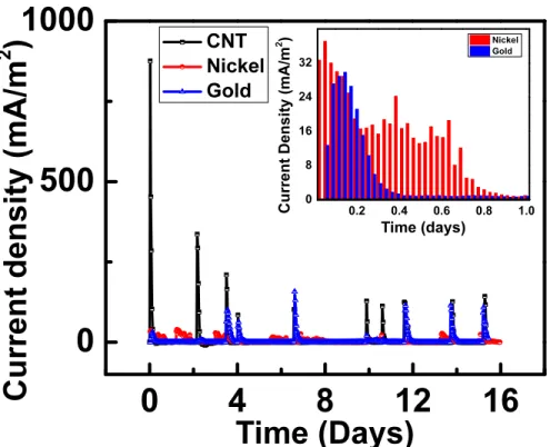
Figure 3.3 Current generation by the CNT, gold, nickel MFCs ... 76
Figure 3.4 Maximum current and power production from CNT, gold, nickel MFCs ... 81
Figure 4.2 Current and power density curves for aluminum contact... 95
Figure 4.3 Power density curve for Co anode contact areas... 97
Figure 4.4 Current production for titanium anode contact area... 97
Figure 5.1 Schematic and photograph of 75 µL one- and two- chamber MFCs ... 106
Figure 5.2 SEM image of graphene with bacteria ... 109
Figure 5.3 Current production of one- and two- chamber micro-sized MFCs ... 114
Figure 5.4 Power density curve for one- and two- chamber micro-sized MFCs... 115
Figure 6.1 Schematic of 25 µL flexible MFC with peeled graphene anode... 123
Figure 6.2 Raman spectroscopy confirming multi-layer graphene... 125
Figure 6.3 Photographs of peeling and assembly process of 25 µL flexible MFC... 126
Figure 6.4 Current production of 25 µL flexible MFC... 127
Figure 6.5 Power density curve of 25 µL flexible MFC... 129
Figure 7.1 MFC process diagram... 136
Figure 7.2 Schematic and photographs of the flexible MFC with graphene on copper anode, air cathode, and syringe tips for easy insertion of fuel... 140
Figure 7.3 Current generation and power density curves using saliva as fuel... 142
Figure 7.4 Current generation and power density curves using high concentrations of acetate as fuel... 147
Figure 8.1 Schematic of micro-sized MFCs in series ... 159
Figure 8.2 Photograph of micro-sized MFCs in series ... 160
Figure 8.3 Flow diagram of micro-sized MFC in series... 160
Figure A1.1 Summarized fabrication process flow ... 163
Figure A1.2 Digital photograph of the experimental setup. ... 165
Figure A1.3 Polarization plot comparing MWCNT and carbon cloth (CC) anode ... 166
Figure A3.1 Current over time for cobalt Ohmic and Schottky devices ... 168
Figure A3.2 Polarization curve for Ti Schottky device ... 169
Figure A4.1 Optical image and Raman spectrum of graphene... 171
LIST OF TABLES
Table 1.1 Dissertation organization by micro-sized MFC themes and studies
corresponding to papers published/submitted... 40
Table 2.1 Summary of the characteristics and performances of demonstrated micro-sized MFCs. ... 57
Table 5.1 Design considerations for sustainable micro-sized microbial fuel cell. ... 111
Table 7.1 Table of Air Cathode micro-sized MFCs ... 143
Chapter 1 Introduction
1.1 The Water-Energy Nexus
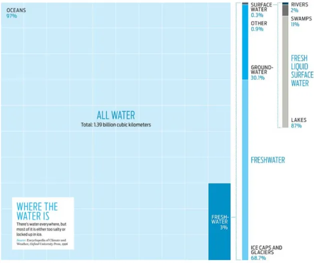
Today, the scarcity of potable water is a priority concern in the world. 1.2 billion people do not have access to safe drinking water; 2.6 billion people have little or no sanitation. Millions of people die every year, almost 4,000 children a day, from water borne diseases1,2. Since water greatly affects food production and the environment, economies are also affected by lack of access to clean water. Only 3% of the earth’s water is fresh water with over 60% of fresh water locked in glaciers and ice3 (Figure 1.1). It is therefore imperative we utilize efficiently the fresh water we do have available in the form of groundwater, lakes, rivers, and swamps. In order to be used, this water must be collected, transported, distributed, and treated which requires energy.
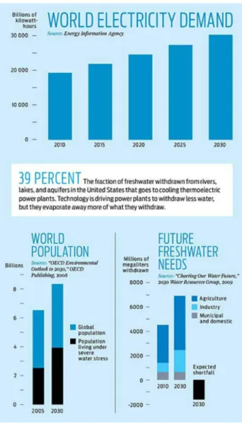
Water and energy are inextricably linked. In the US alone, it is estimated that 5% of the electricity produced is used in the transport and treatment of water4. Desalination techniques have been introduced to convert salt water to fresh water but many of the most advanced water treatment and desalination techniques, such as Reverse Osmosis, require large amounts of energy to operate1,5. Water production depends on energy and energy production depends on water. Electricity production, requiring approximately 39% of the freshwater collected in order to run thermoelectric cooling towers, is the second largest water consumer in the United States behind agriculture (Figure 1.2)3. To put it another way, on just one average day in the United States, there are more than 500 billion liters of
freshwater that are consumed through power plants throughout the country which is more than twice the amount of water that flows through the Nile3. On the global scale, 15% of the world’s total freshwater withdrawal in 2010 was used to produce energy and water use by the energy sector is expected to increase by 20% over 2010-20356.
Figure 1.1 Global water resources
With limited water resources, it is important to explore all options of obtaining fresh water. Reproduced from: The coming clash between water and energy, IEEE Spectrum Special Report: Water vs Energy. http://spectrum.ieee.org/static/special-report-water-vs-energy. 2010.
Overall, global energy consumption is projected to increase by 56 percent until 2040 (Figure 1.3)7. Developing nations outside of the Organization for Economic Cooperation
and Development (non-OECD) such as India and China account for more than 85 percent of the increase in global energy demand in this time frame due to expanding populations and strong economic growth7.
Figure 1.2 World electricity demand
Water and energy are inextricably linked and with a growing population comes an increasing need for electricity and freshwater. Reproduced from: The coming clash between water and energy, IEEE Spectrum Special Report: Water vs Energy. http://spectrum.ieee.org/static/special-report-water-vs-energy. 2010.
Although fossil fuels, including oil, gas, and coal, are forecasted to remain the primary sources of energy globally, their supply cannot last forever6,7. Other sources of energy must be found, not necessarily as a substitute for fossil fuels, but combined with fossil fuels to create a more diversified global energy portfolio that can sustainably provide energy to the growing population in the upcoming decades. New technologies should be explored to gather energy efficiently from the sun, wind, and wastes.
The continued search for clean and renewable energy sources and energy conservation techniques is an imperative of the world population today. There is one Figure 1.3 Global energy consumption
Global energy consumption (expressed in quadrillion Btu) is expected to double from 1990 to 2040 with non-OECD countries consuming the majority of energy in the future. Reproduced from: U.S. Energy Information Administration. International Energy Outlook 2013. http://www.eia.gov/forecasts/ieo/world.cfm
technology, even though it is only in laboratory phase currently, that addresses both energy and water challenges by treating waste water and simultaneously producing renewable energy, the Microbial Fuel Cell (MFC)8. Independent of the amount of sun or wind, the MFC converts organic matter in waste waters into electricity using bacteria. Although not expected to overtake fossil fuels as a major energy supplier, the unique ability of the MFC to turn liquid wastes into electricity can play a role as one of the newest approaches in diversifying the global energy and water portfolio. Therefore, the exploration and optimization of MFCs is important in understanding the limits and possibilities of the technology and in making the mass commercialization of MFCs a reality.
1.2 Microbial Fuel Cell Background
The earliest MFC concept was demonstrated by Potter in 1910 when he produced electrical energy from bacteria using platinum electrodes9. Since then, there was not
much interest in MFC work until the 1980s when the addition of electron mediators were found to increase the current and power production in MFCs10,11. The continuous addition of electron mediators made applications of the MFC outside of the laboratory infeasible and the real breakthrough in MFC technology came in 1999 when it was found that the addition of electron mediators was not necessary and the bacteria themselves could transfer electrons directly to the anode12.
A microbial fuel cell is an innovative device for energy production that captures the electricity produced by bacteria during natural decomposition of organic matter8,13,14.
Bacteria can decompose organic matter from a wide variety of fuels that are generally abundant and non-toxic, ranging from environmental liquids like domestic and industrial wastewaters to medical liquids like urine and glucose, making the process of refueling simple and inexpensive15. Most frequently, wastewater is used which serves a dual purpose because when the bacteria decompose the matter to produce electricity they are also cleaning the water.
Microbial Fuel Cells typically have an anode and a cathode separated by a proton exchange membrane in a two chamber set up (Figure 1.4). Both electrodes must be conductive and the anode must also be biocompatible as bacteria introduced into the system will form a biofilm on the anode. Certain bacteria found naturally in waste water or grown as a pure culture have unique electrogenic qualities in its ability to decompose organic materials and release electrons extra-cellularly8. When an organic liquid feed is Figure 1.4 Schematic of basic components of a microbial fuel cell
Basic components and functions of the microbial fuel cell including an anode where bacteria grow and a cathode.
inserted, the bacteria oxidize the substrate and produce protons and electrons. The protons pass through the proton exchange membrane to the cathode and electrons are transferred through an external circuit from the anode to the cathode driving an external load and reducing the electron acceptor at the cathode.8,16
One of the major challenges with current MFCs is their long testing times (from weeks to months) making it difficult to evaluate new materials or conditions quickly, a necessity in determining the optimal materials for a new technology. The first miniaturized MFC was developed in 2006 with the goal of cutting down testing time to be able to “turn on” an MFC (inoculate with bacteria) in seconds or minutes instead of days and to complete a full run of the experiment in hours instead of weeks17.
Development of milli-liter and micro-liter scale MFCs have essentially continued with applications expanding into remote and self-sustained power sources as well as on-chip powering. By using microfabrication, the fabrication and assembly of micro-sized MFCs is inexpensive and can be mass-produced. It is the exploration and optimization of the micro-sized MFC that is the overall objective of this dissertation.
1.3 Dissertation Objective and Themes
The development of micro-sized MFCs requires an interdisciplinary understanding of environmental and water engineering, semiconductors and nanotechnology, as well as materials science. With this in mind, the objective of the dissertation research was to take a holistic approach to explore and improve upon many key features of the micro-sized MFC, developing a variety of reactors (volumes from 1- 75 µL) to test nano-engineered
materials and new fuels in an effort to increase power and current production and push micro-sized MFCs one step closer to actual implementation into usable devices and out of the laboratory. With fewer than 20 studies done on micro-sized MFCs18, there are numerous gaps in knowledge related to this area. Therefore, many topics are explored in our effort to optimize micro-sized MFCs and we asked questions such as: Can we fabricate the smallest ever MFC? Can we make the anode a nano-sized forest instead of a flat surface? Can we make the micro-sized MFC completely mobile? Can the MFC be powered by saliva?
There are four major areas or themes of micro-sized MFCs that were explored and improved upon in the studies included in this dissertation. Each theme will be presented below with a general background explanation of its role in the micro-sized MFC as well as a brief introduction of the specific variables within that theme that were tested. The four themes are: Anode, Cathode, Reactor Design, and Fuels.
1.3.1 Theme 1: Anode
The first theme explored in the optimization of micro-sized MFCs is the anode material. The general requirements for all MFC electrodes include good conductivity, chemical stability, non-corrosivity, high mechanical strength and low cost8,19. As the anode must also support the growth of bacteria in an MFC, it requires special characteristics to better enable biocompatibility and adhesion of bacteria to the surface, such as high surface-to-volume ratios20 and efficient electron transfer between bacteria and electrode surface21.
The most versatile and frequently used anode material in macro-scale MFCs is carbon-based typically due to its stability in microbial cultures, high electric conductivity and large surface areas22. Non-corrosive metals, such as gold, have also been used, especially in micro-sized fuel cells, due to their simple fabrication requirements23. Different carbon forms have been used to increase surface areas and promote microbial adhesion to the surface, including graphite24, carbon cloth25,26, carbon paper27, carbon foam28, and reticulated vitrified carbon29. Higher power production in MFCs is possible with increased surface area-to-volume ratios and novel anode designs22,28. For example, graphite fiber brushes have been used to increase surface-to-volume ratios but their use in micro-sized cells is difficult due to their bulky architecture22. Therefore, we sought to
utilize nano-engineered carbon materials into a micro-sized MFC, particularly carbon nanotubes (CNTs) and graphene. The properties of these carbon nanomaterials and their use in microbial fuel cells will be described including a note on the introduction on silicon process technology into MFC anodes. Also, a subset theme in anode exploration will be introduced, anode contact area engineering enhancements that increase the amount of electrons that can be shuttled from the anode to the cathode. Common semiconductor contact materials were chosen and compared, including nickel, aluminum, titanium, and cobalt, on two different anode locations with different fabrication methods.
Carbon Nanotubes
Carbon nanotubes (CNTs) are a graphene sheet of sp2 carbon rolled into tubes of tunable diameter and length that can be capped or not30,31. The CNTs can be subdivided
into two types: Single Walled Carbon Nanotubes (SWCNTs) and Multi Walled Carbon Nanotubes (MWCNTs) which consists of multiple concentric nanotubes.
Although first found in the 1950s, the most profound CNT research occurred in the past decade (Figure 1.5)30. CNTs have exceptional electrical and mechanical properties with the ability to carry current up to 109 A-cm2 32 and a tensile strength of over 100
GPa33, over 10 times higher than any other industrial fiber. While both types of CNTs are highly conductive and can be purified in mineral acids to remove their cap and functionalized to increase biocompatibility, the use of MWCNTs in electrochemical applications is generally preferred31. MWCNTs are metallic conductors while SWCNTs can be semi-conductors depending on diameter and chirality31. Also, MWCNTs can be
fabricated rapidly, without requiring as much precision, and inexpensively, making production in bulk possible30. The ability to align MWCNTs into CNT forests of a specified size increases control of the CNTs for use in intended applications and robustness of the surface34.
Figure 1.5 Trends in carbon nanotube research
Trends in CNT research including publications, patents, and production capacity. Reproduced from: De Volder, M.F.; Tawfick, S.H.; Baughman, R.H.; Hart, A.J. Carbon Nanotubes: Present and Future Commercial Applications. Science. 2013, 339, 535-539.
Because of the unique electrical and structural properties of carbon nanotubes, recent microbial fuel cell studies have included CNTs anodes generally in a hybrid form such as carbon nanotubes integrated into carbon cloth35, textiles36, and polymer composites37 finding the CNT enhanced anode outperformed the control. These hybrid anodes blend CNTs with other materials and are not CMOS compatible, though, making these anodes unable to be integrated on-chip for micro-scale applications. Therefore, we integrated pure MWCNTs grown in an aligned forest on top of a silicon chip as anode as they have excellent electrochemical capabilities, can be fabricated directly on chip, and can be functionalized to improve cell adhesion.
The use of pure MWCNTs as anode can be found in Chapters 2 and 3.
Graphene
Although graphene is the building block of carbon nanotubes, the material, itself, was not isolated until 200438. Since then, there has been much interest by scientists to
incorporate graphene into electrochemical applications due to its reported large electrical conductivity, vast surface area, and low production costs39,40. Graphene is the first two-dimensional (2D) atomic crystal easily available for our use. At one atom thick, it is the thinnest known material and the strongest ever measured41. Many of its material parameters, such as mechanical elasticity, strength and stiffness as well as high electrical and thermal conductivities are exceptional. Combining properties of graphene has allowed many researchers to envision breakthrough technologies integrating the material into current systems or disrupting the status quo technologies completely.
These properties are currently only achieved with the purest of graphene samples in the laboratory and scientists are rapidly trying to make pure graphene in an easier and mass-produced method which is expected to then attract wide-scale industrial attention (Figure 1.6)42.
In Microbial Fuel Cells, graphene was first introduced as a cathode and then as an anode. In a cathode, graphene acts as an inexpensive replacement to precious-metal electrocatalysts which aid in the oxygen reduction reaction43,44. As an anode, there are a
few studies in which a hybrid graphene or graphene oxide modified anode was formed on other anode materials like carbon cloth45-47, stainless steel48 or polyaniline49. The use of pure graphene, utilized directly after growth without requiring combinations with other materials, had not been tested as an MFC anode nor had any graphene studies been performed in micro-sized MFCs.
Figure 1.6 Methods to fabricate graphene
Different methods of producing graphene produce materials with varied values of quality and cost. As graphene becomes cheaper to produce in bulk, its use in industrial applications is expected to increase. Reproduced from: Novoselov, K.S. et al. A roadmap for graphene. Nature. 2012, 490, 192-200.
Therefore, we tested three different types of pure graphene anodes in micro-sized MFCs.
Graphene grown on nickel on a silicon chip is found in Chapter 5.
Peeled graphene and nickel thin film used as a flexible anode is found in Chapter 6. Graphene grown on a copper foil found is in Chapter 7.
Silicon Process Technology
As the second most abundant element in the earth’s crust, silicon is found everywhere and in its purest form, plays a critical role in the global economy and technology through silicon process technology, the most frequently used technology in fabrication50. Almost all of our modern day electronics require advanced circuits and functions fabricated onto a silicon chip. The importance of silicon cannot be overstated and, therefore, the building of a microbial fuel cell onto a silicon chip is essential in integrating MFC technology as a miniature power source into hand held electronics.
While a variety of micro-sized MFCs fabricate their anodes on top of glass or polydimethylsiloxane (PDMS)18, only two have used silicon51,52 leaving a large area open for optimization of micro-sized MFCs in this area.
Contact area engineering
One of the most important features of designing a high power micro-sized MFC is the contact area to the anode. The contact area can be considered like a gate at the anode that determines how many electrons can pass through based on its inherent resistance and conductivity properties. The performance of the contact area can, therefore, be improved by material selection and position21. In macro-scale MFC designs, a titanium or stainless steel wire is often pressed to the electrode to provide contact with the surface8. By borrowing contact engineering knowledge from the semiconductor industry, we can improve upon contact areas to be able to increase current production as well as utilize silicon process technology to more easily access the electrons from a different location on the silicon instead of having to directly touch the anode.
When considering contact engineering options in micro-sized MFCs there are three parameters that can be varied: 1) location of the contact area 2) material of the contact 3) method of fabricating the contact material. There are two novel examples of contact engineering described in this dissertation.
In the first example found in Chapter 2, the anode is fabricated onto a 25 mm2 area on a silicon chip and the contact area is located on the topside of the silicon (same side as the anode) but 2 mm from the anode. The material used is nickel with has been annealed to make nickel silicide.
The second example which is found in Chapter 4, utilized a contact area located on the bottom side of the silicon chip (opposite side as the anode). The materials used are
aluminum, titanium, and cobalt fabricated in both thin film (Schottky) and annealed (Ohmic) methods.
1.3.2 Theme 2: Cathode
The second theme explored in the optimization of micro-sized microbial fuel cells is the cathode where we looked to optimize both the cathode and electron acceptor materials to make a practical, usable micro-sized MFC. The material selection for the cathode, like that of the anode, requires a highly conductive material and is most typically carbon in macro-scale MFCs8. Micro-sized MFCs, on the other hand, have most
frequently used gold as a cathode as it is easily fabricated18,52,53. Gold, though, is expensive and therefore, unsustainable in any scaled up version of the micro-sized MFC. Also, silicon manufacturing foundries do not allow access of gold to silicon based devices because of its high diffusivity to shorten integrated circuits unintentionally. Therefore, we chose to utilize a carbon cathode in all of our micro-sized MFCs.
Variations on the carbon cathode were made depending on the electron acceptor chosen. MFCs, particularly micro-sized, are often constrained by the use of liquid chemical electron acceptors that require a two-chamber architectural configuration and continuous refilling when the electron acceptor is depleted making it an unsustainable design feature for use outside of the laboratory. Thus, the use of oxygen in the air has been explored in macro-scale MFCs as an electron acceptor, as it is readily available and does not need to be regenerated8,54,55. The use of oxygen as an electron acceptor requires some type of air cathode in which protons can reach the cathode on the inside and air on
the outside. Typical air cathodes in macro-scale MFCs utilize carbon cloth with a painted platinum side facing inside (towards the liquid fuel) while the outside has a layer of hydrophobic carbon/polytetrafluoroethylene (PTFE) so that the liquid fuel does not leak from the device55. Although air cathodes are used in larger scale MFCs, ferricyanide is almost exclusively used in micro-sized MFCs18,52,53 since it is generally found to produce
higher power densities than more readily available electron acceptors such as oxygen8,19. Oxygen is thermodynamically favorable to ferricyanide as seen in the following equations, but ferricyanide is still found to increase power by 1.5 to 1.8 times oxygen in larger scale MFC studies19 partly because it has a low over-potential making the cathode working potential close to the open circuit potential8,56,57.
O2 + 4H+ + 4e-→ 2 H2O with a theoretical cathode potential of 1.229 V
Fe(CN)63- + e- → Fe(CN)64- with a theoretical cathode potential of 0.361 V
In order to make sustainable micro-sized MFCs that can be scaled up or be self sustained power generators, though, the use of an air cathode must be explored at the micro-scale. Two micro-sized MFC studies have recently introduced the use of air cathodes with proton exchange membranes hot pressed onto a carbon cloth cathode58,59. Membranes increase cost and increase internal resistance of a device which lowers overall power production19,55. Therefore, we have introduced an air cathode in a membrane-less one-chamber micro-sized MFC system for the first time, in an effort to make a more sustainable and mobile device.
1.3.3 Theme 3: Reactor design
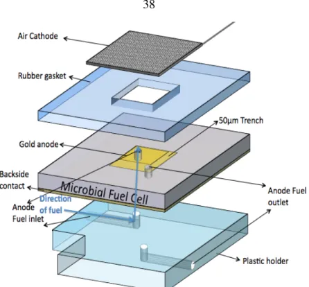
The variety of materials discussed in themes one and two must be assembled and utilized into the final system design which ultimately affects the efficiency of the MFC as well as power and current production8. Therefore, the third theme of this dissertation is the building high power and current producing reactors with sustainable and usable designs in mind. Four different reactor types were tested with variations made to accommodate different applications of the micro-sized MFCs. The first is the high power and current two-chamber device that at 1.25 µL was the smallest ever fabricated at the time of its publication (Figure 1.7). Similar stacked architecture two-chamber devices exist such as the 1.5 µL MFC by Qian et al.51 and the 4.5 µL MFC by Choi et al.53. As this device required the use of the chemical ferricyanide which is unsustainable due to the continual need to be refilled, the next device was made with conditions closer to larger scale MFCs using an air cathode in a larger (75 µL) plastic structure with titanium wire contacts (Figure 1.8). The contact to the nano-engineered anode was difficult in this set up and leaks were also prone to occur leading to the third design. This design continued to utilize an air cathode in a 25 µL device but with innovative bottom feed holes etched through the silicon anode to decrease leaks as well as bottom contact to the anode (Figure 1.9).
All three of the previous designs utilized anodes on silicon chips to prepare for applications integrated on the chip. We also developed a design for possible applications that did not require the complexity of integrated circuitry on a silicon chip such as a
power source for point-of-care diagnostics. Emerging medical Lab-on-a-chip devices are being developed as point-of-care diagnostics used to diagnose infectious diseases and perform drug and bacterial resistance tests specifically in the developing world where state-of-the-art laboratory facilities are not available. These applications require a device with a robust and inexpensive architecture that is easy to use and only requiring the user to input commonly used materials60. Micro-sized MFCs can play a valuable role in point-of-care diagnostics if designed accordingly. Although there are many factors that need to be addressed before a device would be ready for field application, we focused on the development of an inexpensive robust architecture. The final design (25 µL) was made out of inexpensive rubber to be flexible, robust, and easy to feed as syringe tips were incorporated into the device (Figure 1.10). Initial studies have been made on running micro-sized MFCs in series for increased power production and initial results, including photographs, will be included in the Outlook in Chapter 8.
The 1.25 µL reactor is found in Chapter 2. The 75 µL reactor is found in Chapters 3, 5.
The 25 µL reactor with bottom feed holes is found in Chapter 4. The 25 µL reactor with flexible structure is found in Chapters 6, 7.
Figure 1.7 The 1.25 µL two-chamber micro-sized MFC reactor.
Figure 1.9 The 25 µL reactor with bottom feed holes and backside anode contact.
Figure 1.10 The 25 µL flexible reactor made using inexpensive rubber as support and anode chamber.
1.3.4 Theme 4: Fuels
The last major theme explored in micro-sized MFCs was in the utilization of a wide variety of possible fuels used to power the MFC. (As a note, the term “fuel” will be used throughout to describe the liquid fed to the bacteria since the term more typically used in MFC literature, “substrate”, means the silicon wafer in microfabrication terminology.) Typically, acetate is utilized at 1 g/L in phosphate buffer solution (composed of NH4Cl,
NaH2PO4 H2O, and KCl) with vitamins and minerals as described previously61 since it
is a simple carbon material easily able to be converted into energy by the electrogenic bacteria8,19. A variety of fuels have been explored in the environmental and medical fields
including domestic62,63 and industrial64,65 waste waters as well as urine66 and glucose15,67. Here, the use of saliva as a fuel was tested which opens up the possibility of biomedical applications running on saliva or miniature power generators usable anywhere. Also, initial studies on the use of liquid yogurt whey have been done to explore the use of MFCs in new applications. The Greek yogurt industry is currently facing an environmental waste disposal dilemma with strained liquid yogurt whey waste produced from their yogurt manufacturing68 and the micro-sized MFC is the perfect testing venue to test this fuel before scaling up into larger scale MFCs. Preliminary results from the yogurt whey research are found in the Outlook of Chapter 8.
1.4 Organization of Chapters
As each individual micro-sized MFC study was a combination of the four themes, every chapter in this dissertation will correspond to a first author publication/submission. Each paper will be introduced with an abstract connecting the objectives and results of the paper with the four overall themes above with a conclusion at the end of the dissertation.
As a reference, below is a table of each chapter and paper labeled with the overall thematic areas described above. As part of the Chapter 8, the Outlook section is composed of coauthored publications (in preparation) of further work in MFCs including testing novel fuels and integrated architecture designs.
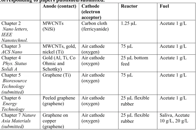
Table 1.1 Dissertation organization by micro-sized MFC themes and studies corresponding to papers published/submitted.
Anode (contact) Cathode (electron acceptor) Reactor Fuel Chapter 2 Nano letters, IEEE Nanotechnol. MWCNTs (NiSi) Carbon cloth (ferricyanide) 1.25 µL Acetate 1 g/L Chapter 3 ACS Nano MWCNTs, gold, nickel (Ti) Air cathode (oxygen) 75 µL Acetate 1 g/L Chapter 4 Phys. Status Solidi A
Gold (Al, Ti, Co Ohmic and Schottky) Air cathode (oxygen) 25 µL bottom feed Acetate 1 g/L Chapter 5 Bioresource Technology (submitted)
Graphene (Ti) Air cathode (oxygen) 75 µL Acetate 1 g/L Chapter 6 Energy Technology Peeled graphene (graphene) Air cathode (oxygen) 25 µL flexible rubber Acetate 1 g/L Chapter 7 Nature Asia Materials (submitted) Graphene on copper (graphene) Air cathode (oxygen) 25 µL flexible rubber Saliva, Acetate 10 g/L, 20 g/L
1.5 Literature Cited
1. Shannon, M.A.; Bohn, P.W.; Elimelech, M.; Georgiadis, J.G.; Marinas, B.J.; Mayes, A.M. Science and technology for water purification in the coming decades. Nature. 2008, 452, 301-310.
2. Montgomery, M. A.; Elimelech, M. Water and sanitation in developing countries: including health in the equation. Environ. Sci. Technol. 2007, 41, 17–24.
3. The coming clash between water and energy, IEEE Spectrum Special Report: Water vs Energy. http://spectrum.ieee.org/static/special-report-water-vs-energy. 2010.
4. Logan, B. E. Invited Editorial: Energy Diversity Brings Stability. Environ. Sci. Technol. 2006, 40, 5161.
5. Veerapaneni, S., Long, B., Freeman, S. & Bond, R. Reducing energy
consumption for seawater desalination. J. Am. Water Works Assoc. 2007, 99, 95– 106.
6. International Energy Agency. World Energy Outlook 2012. < http://www.worldenergyoutlook.org/publications/weo-2012>.
7. U.S. Energy Information Administration. International Energy Outlook 2013. http://www.eia.gov/forecasts/ieo/world.cfm
8. Logan, B. E. Microbial Fuel Cells, 1st ed.; John Wiley & Sons, Inc.: Hoboken, New Jersey, 2008.
9. Potter, M.C. Electrical effects accompanying the decomposition of organic compounds. Proc R Soc Ser B. 1912, 84, 260–276.
10. Allen, R.M.; Bennetto, H.P. Microbial fuel-cells: electricity production from carbohydrates. Appl Biochem Biotechnol. 1993, 39, 27–40.
11. Ieropoulos, I.A.; Greenman, J.; Melhuish, C.; Hart, J. Comparative study of three types of microbial fuel cell. Enzyme Microb Tech. 2005, 37, 238–245.
12. Kim, B.H.; Kim, H.J.; Hyun, M.S.; Park, D.H. Direct electrode reaction of Fe(III)-reducing bacterium, Shewanella putrifaciens. J Microbiol Biotechnol. 1999, 9, 127–131.
13. Lovley, D. R. The microbe electric: conversion of organic matter to electricity. Curr. Opin. Biotechnol. 2008, 19, 564.
14. Rittmann, B. E. Opportunities for renewable bioenergy using microorganisms. Biotech. and Bioengr. 2008, 100, 203.
15. Pant, D.; Van Bogaert, G.; Diels, L.; Vanbroekhoven, K. A Review Of The Substrates Used In Microbial Fuel Cells (MFCs) For Sustainable Energy Production. Bioresour. Technol. 2010, 101, 1533-1543.
16. Zhou, M.; Wang, H.; Hassett, D.J.; Gu, T. Recent Advances In Microbial Fuel Cells (MFCs) And Microbial Electrolysis Cells (MECs) For Wastewater Treatment, Bioenergy And Bioproducts. J. Chem. Technol. Biotechnol. 2013, 88, 508-518.
17. Crittenden, S.R.; Sund, C.J.; Sumner, J.J. Mediating electron transfer from bacteria to a gold electrode via a self-assembled monolayer. Langmuir. 2006, 22, 9473–9476
18. ElMekawy, A.; Hegab, H.M.; Dominguez-Benetton, X.; Pant, D. Internal resistance of microfluidic microbial fuel cell: Challenges and potential opportunities. Bioresour. Tech. 2013, 142, 672-682.
19. Logan, B.E. et al. Microbial Fuel Cells: Methodology and Technology. Environ. Sci. Technol. 2006, 40, 5181-5192.
20. Wei, J.; Liang, P.; Huang, X. Recent Progress in electrodes for microbial fuel cells. Bioresource Technol. 2011, 102, 9335-9344.
21. Inoue, S.; Parra, E.A.; Higa, A.; Jiang, Y.; Wang, P.; Buie, C.R.; Coates, J.D.; Lin, L. Structural Optimization Of Contact Electrodes In Microbial Fuel Cells For Current Density Enhancements. Sens. Actuators, A. 2012, 177, 30-36.
22. Logan, B.E.; Cheng, S.; Watson, V.; Estadt, G. Graphite fiber brush anodes for increased power production in air-cathode microbial fuel cells. Environ. Sci. Technol. 2007, 41, 3341–3346.
23. Qian, F.; Morse, D. Miniaturizing microbial fuel cells. Trends in Biotechnol. 2011, 29, 62-69.
24. Richter, H.; McCarthy, K.; Nevin, K. P.; Johnson, J. P.; Rotello, V. M.; Lovley, D. R. Electricity generation by Geobacter sulfurreducens attached to gold electrodes. Langmuir. 2008, 24, 4376.
25. Fan, Y. Z.; Hu, H. Q.; Liu, H. Enhanced coulombic efficiency and power density of air-cathode microbial fuel cells with an improved cell configuration. J. Power Sources. 2007, 171, 348.
26. Cheng, S.; Liu, H.; Logan, B. E. Power generation in a continuous flow MFC with advective flow through the porous anode and reduced electrode spacing. Environ. Sci. Technol. 2006, 40, 2426.
27. Min, B.; Logan, B. E. Continuous electricity generation from domestic wastewater and organic substrates in a flat plate microbial fuel cell. Environ. Sci. Technol. 2004, 38, 5809.
28. Chaudhuri, S. K.; Lovley, D. R. Electricity generation by direct oxidation of glucose in microbial fuel cells. Nat. Biotechnol. 2003, 21, 1229.
29. He, Z.; Minteer, S. D.; Angenent, L. T. Electricity generation from artificial wastewater using an upflow microbial fuel cell. Environ. Sci. Technol. 2005, 39, 5262.
30. De Volder, M.F.; Tawfick, S.H.; Baughman, R.H.; Hart, A.J. Carbon Nanotubes: Present and Future Commercial Applications. Science. 2013, 339, 535-539.
31. Gooding, J.J. Nanostructuring electrodes with carbon nanotubes: A review on electrochemistry and applications for sensing. Electrochimica Acta, 2005, 50, 3049-3060.
32. Wei, B.Q.; Vajtai, R.; Ajayan, P. M. Reliability and current carrying capacity of carbon nanotubes. Appl. Phys. Lett. 2011, 79, 1172.
33. Peng, B. et al. Measurements of near-ultimate strength for multiwalled carbon nanotubes and irradiation-induced crosslinking improvements. Nat. Nanotechnol. 2008, 3, 626.
34. Li, J. et al. Carbon nanotube nanoelectrode array for ultrasensitive DNA detection. Nano Lett. 2003, 3, 597.
35. Tsai, H. Y.; Wu, C. C.; Lee, C. Y.; Shih, E. P. Microbial fuel cell performance of multiwall carbon nanotubes on carbon cloth as electrodes. J. Power Sources. 2009, 194, 199.
36. Xie, X.; Hu, L.; Pasta, M.; Wells, G. F.; Kong, D.; Criddle, C. S.; Cui, Y. Three- dimensional carbon nanotube-textile anode for high-performance microbial fuel cells. Nano Lett., 2011, 11, 291.
37. Qiao, Y.; Li, C. M.; Bao, S. J.; Bao, Q.L. Carbon nanotube/polyaniline composite as anode material for microbial fuel cells. J. Power Sources. 2007, 170, 79.
38. Novoselov, K.S. et al. A.A. Firsov. Electric Field Effect in Atomically Thin Carbon Films. Science. 2004, 306, 666-669.
39. Castro, A. H. et al. The electronic properties of graphene. Rev. Mod. Phys. 2009, 81, 109-162.
40. Brownson, D.A.; Kampouris, D.K.; Banks, C.E. An overview of graphene in energy production and storage applications. J. Power Sources. 2011, 196, 4873-4885.
41. Geim, A.K. Graphene: Status and Prospects. Science. 2009, 324, 1530-1534.
42. Novoselov, K.S. et al. A roadmap for graphene. Nature. 2012, 490, 192-200.
43. Li, Y. et al. An oxygen reduction electrocatalyst based on carbon nanotube– graphene complexes. Nature Nanotech. 2012, 7, 394-400.
44. Ren, Y. et al. Effect of polyaniline-graphene nanosheets modified cathode on the performance of sediment microbial fuel cell. J. Chem. Technol. Biotechnol. 2013, 88, 1946-1950.
45. Xiao, L. et al. Graphene particles for microbial fuel cell electrodes. J. Power Sources. 2012, 208, 187-192.
46. Liu, J. et al. Graphene/carbon cloth anode for high-performance mediatorless microbial fuel cells. Bioresour. Technol. 2012, 114, 275-280.
47. Yuan, Y.; Zhou, S.; Zhao, B.; Zhuang, L.; Wang, Y. Microbially-reduced graphene scaffolds to facilitate extracellular electron transfer in microbial fuel cells. Bioresour. Technol. 2012, 116, 453-458.
48. Zhang, Y. et al. A graphene modified anode to improve the performance of microbial fuel cells. J. Power Sources. 2011, 196, 5402-5407.
49. Yong, Y.; Dong, X.; Chan-Park, M.; Song, H.; Chen, P. Macroporous and monolithic anode based on polyaniline hybridized three-dimensional graphene for high-performance microbial fuel cells. ACS Nano. 2012, 6, 2394-2400.
50. Meindl, J.D.; Chen, Q.; Davis, J.A. Limits on silicon nanoelectronics for terascale integration. Science. 2001, 293, 2044-2049.
51. Qian, F.; Baum, M.; Gu, Q.; Morse, D. E. A 1.5 µL microbial fuel cell for on-chip bioelectricity generation, Lab Chip. 2009, 9, 3076.
52. Chiao, M.; Lam, K. B.; Lin, L. Micromachined microbial and photosynthetic fuel cells. J. Micromech. Microeng. 2006, 16, 2547.
53. Choi, S.; Lee, H.; Yang, Y.; Parameswaran, P.; Torres, C. E.; Rittmann, B. E.; Chae; J. A µL-scale micromachined microbial fuel cell having high power density. Lab Chip. 2011, 11, 1110.
54. Sell, D.; Kramer, P.; Kreysa, G. Use of an oxygen gas diffusion cathode and a three-dimensional packed bed anode in a bioelectrochemical fuel cell. Appl. Micrbiol. Biotechnol. 1989, 31, 211-213.
55. Cheng, S.; Liu, H.; Logan, B. Increased Performance Of Single-Chamber Microbial Fuel Cells Using An Improved Cathode Structure. Electrochem. Comm. 2006, 8, 489-494.
56. Ter Heijne, A.; Hamelers, H.V.M.; De Wilde, V.; Rozendal, R.A.; Buisman, C.J. A Bipolar Membrane Combined with Ferric Iron Reduction as an Efficient Cathode Sytem in Microbial Fuel Cells. Environ. Sci. Technol. 2006. 40, 5200-5205.
57. You, S.; Zhao, Q.; Zhang, J.; Jiang, J.; Zhao, S. A microbial fuel cell using permanganate as the cathodic electron acceptor. J. Power Sources. 2006, 162, 1409-1415.
58. Hou, H.; De Figueiredo, P.; Han, A. Air-Cathode Microbial Fuel Cell Array: A Device For Identifying And Characterizing Electrochemically Active Microbes. Biosens. Bioelectron. 2011, 26, 2680-2684.
59. Chen, Y. et al. An Innovative Miniature Microbial Fuel Cell Fabricated Using Photolithography. Biosens. Bioelectron. 2011, 26, 2841-2846.
60. Yager, P.; Domingo, G.; Gerdes, J. Point-of-Care Diagnostics for Global Health. Annu. Rev. Biomed. Eng. 2008, 10, 107–44.
61. Lovley, D.R.; Phillips, E.J.P. Appl. Environ. Microbiol. 1988, 54, 1472-80.
62. Jang, J.K. et al. Construction and operation of a novel mediator- and membrane-less microbial fuel cell. Process Biochem. 2004, 39, 1007–1012.
63. Wang, X. et al. Accelerated start-up of two-chambered microbial fuel cells: effect of positive poised potential. Electrochem. Acta. 2009, 54, 1109–1114.
64. Patil, S.A. et al. Electricity generation using chocolate industry wastewater and its treatment in activated sludge based microbial fuel cell and analysis of developed microbial community in the anode chamber. Bioresour. Technol. 2009, 100, 5132–5139.
65. Feng, Y.; Wang, X.; Logan, B.E.; Lee, H. Brewery wastewater treatment using air-cathode microbial fuel cells. Appl. Microbiol. Biotechnol. 2008, 78, 873–880.
66. Kuntke, P. et al. Ammonium recovery and energy production from urine by a microbial fuel cell. Water Res. 2012, 46, 2627-2636.
67. Catal, T.; Li, K.; Bermek, H.; Liu, H. Electricity production from twelve monosaccharides using microbial fuel cells. J. Power Sources. 2008, 175, 196– 200.
68. Elliot, J. Whey too Much: Greek Yogurt’s Dark Side. Modern Farmer.
http://modernfarmer.com/2013/05/whey-too-much-greek-yogurts-dark-side/. Last Accessed: October 1, 2013.
Chapter 2
Vertically Grown Multi-walled Carbon Nanotube Anode and Nickel Silicide Integrated High Performance Micro-sized (1.25 µL) Microbial Fuel Cell
Abstract
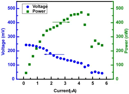
As a new subset of microbial fuel cells, micro-sized microbial fuel cells were first introduced in 2006. In our first micro-sized MFC design, we sought to integrate semiconductor and nanotechnology concepts into the MFC in order to increase current and power production in the first step of creating self-sustained electricity generator for Lab-on-chip and similar integrated devices. Nanotechnology advancements were applied to fabricate a 1.25 µl micro-sized MFC with a nano-engineered anode containing a vertically aligned forest of pure multi-walled carbon nanotubes (MWCNT) on a silicon chip as well as a semiconductor industry standard nickel silicide (NiSi) contact area that allowed the electrons to be transferred to the cathode for the first time without requiring contact with the anode directly. The MWCNTs increased the anode surface-to-volume ratio, which improved the ability of the microorganisms to couple and transfer electrons to the anode. The use of nickel silicide also helped to boost the output current by providing a low resistance contact area to more efficiently shuttle electrons from the anode out of the device. The MFC successfully produced 197 mA/m2 of current and 392
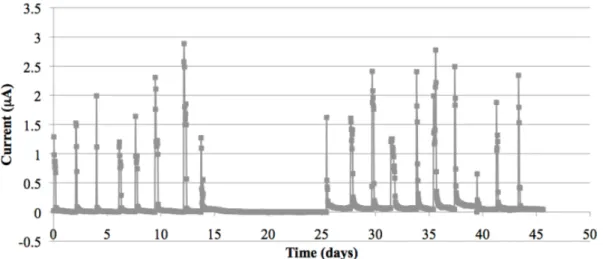
mW/m3 of power. At the time of its fabrication (2011), it was the smallest MFC by volume that had ever been manufactured and published. Unique features include its small size, comparatively high current densities, as well as the use of nickel silicide contact area. The high endurance of the MWCNT anode is highlighted at the end of the chapter
with an excerpt from the IEEE Nanotechnology Conference Proceedings in which a replicate 1.25 µL device was run for over 50 days with repeatable current production.
This chapter was published as∗:
Mink, J.E.; Rojas, J.P.; Logan, B.E.; Hussain, M.M. Vertically Grown Multi-walled Carbon Nanotube Anode And Nickel Silicide Integrated High Performance Microsized (1.25 µL) Microbial Fuel Cell. Nano Lett. 2012, 12, 791-795.
With an excerpt from:
Mink, J.E.; Hussain, M.M. Excellent Endurance Of MWCNT Anode In Micro-Sized Microbial Fuel Cell. IEEE Conf. Nanotechnol., 12th. 2012, 1-4.
2.1 Introduction
Microbial Fuel Cells (MFCs) are an innovative method for generating power that can also be used for treating wastewaters1–3. Milli- to micro-liter scale MFCs provide a unique on-chip power source that could be used at a remote location or in lab-on-a-chip applications making external power sources or refined chemicals unnecessary4. Micro-sized MFCs can also be used for rapid screening of electrode materials and
∗ Reproduced with permission from Mink, J.E.; Rojas, J.P.; Logan, B.E.; Hussain, M.M. Vertically Grown Multi-walled Carbon Nanotube Anode And Nickel Silicide Integrated High Performance Microsized (1.25 µL) Microbial Fuel Cell. Nano Lett. 2012, 12,791-795.
Copyright 2012 American Chemical Society.
© 2012 IEEE. Reprinted, with permission, from J.E. Mink, M.M. Hussain, Excellent Endurance Of MWCNT Anode In Micro-Sized Microbial Fuel Cell, IEEE Conf. Nanotechnol., 12th, August/2012.
electrochemically active microbes4,5. Micro-sized MFCs offer high surface area-to-volume ratios, short electrode distances, and fast response times. Many nanomaterials are electrically conductive and biocompatible with microorganisms. Micro-fabrication techniques can therefore be used not only for precise and inexpensive production of these devices, but also they allow for direct incorporation of advanced nanomaterials, like carbon nanotubes, into the reactor.
2.2 Materials and Methods
2.2.1 Carbon Nanotube Anode
The most versatile and frequently used anode materials are carbon-based. Different carbon forms have been used to increase surface areas and promote microbial adhesion to the surface, including graphite6, carbon cloth7,8, carbon paper9, carbon foam10, and reticulated vitrified carbon11. Higher power production in MFCs is possible with
increased surface area-to-volume ratios and novel anode designs10,12. For example, graphite fiber brushes have been used to increase surface-to-volume ratios but their use in micro-sized cells is difficult due to their bulky architecture12. Because of the unique electrical and structural properties of carbon nanotubes (CNTs), recent studies have included CNTs13–15 and CNT textiles16 in MFC anodes. Several other studies also use DC
and AC electrochemical characterization of CNT-based electrodes, through cyclic voltammetry and electrochemical impedance spectroscopy (EIS), that show enhanced electrochemical properties compared with conventional materials17-21.
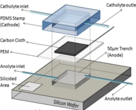
In order to enhance current generation in an MFC, we developed an anode containing a vertically aligned forest of pure multi-walled carbon nanotubes (MWCNT) in a 1.25 µL reactor (Figure 2.1). The vertically aligned MWCNTs were grown with controlled and uniform shapes and sizes using vapor-liquid-solid (VLS) self-assembly processes and micro-fabrication techniques. The specific materials and methods used for assembly of the entire MFC are described in the Supplementary Information in Appendix 1. The MWCNTs had a high surface area-to-volume ratio (66,000 cm-1 before functionalization) that was expected to be helpful for bacterial colonization, and a high electrical conductivity (resistance of 2.1 mΩ m for a single nanotube) to enhance transfer of electrons to the anode surface. Other possible biological advantages of the MWCNT surface included increased biocompatibility, chemical stability, catalytic activity, and Figure 2.1 3D Schematic and images of the fabricated 1.25 µL microbial fuel cell (a) Schematic (3D) of various components of the fabricated vertically stacked microbial fuel cell; (b) the digital image of the assembled microbial fuel cell in plexiglass clamp showed sidewise it occupying 5 cm on each side and (c) transmission electron
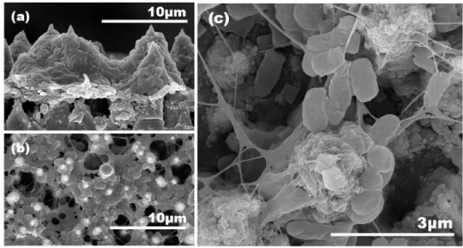
resistance to decomposition16,22,23. Surface properties such as hydrophilicity, hydrophobility, and functional groups can affect cell adhesion, growth, and metabolism. A functionalization process was performed on the CNTs in which they were cleaned in an acid treatment (nitric and sulfuric acids) to remove residual metal catalysts and other impurities. The acid treatment also has been found to improve cell adhesion by thickening the MWCNTs in an oxidation process that generates carboxylic groups in the walls and tips of the MWCNTs, and forms 3D structures using capillary tensile forces, which make the MWCNTs collapse onto each other24. After functionalization, the average height of the CNTs was 35 mm and their diameter ranged from 200 to 400 nm (Figure 2.2).
An MFC electrode requires a contact area to measure the voltage generated. In macro scale MFC designs, a titanium or stainless steel wire is often pressed to the electrode to provide contact with the surface1. Here, we integrated a low resistance nickel silicide contact area onto the silicon surface so that the electrode contact point did not directly touch the anode. This method provided good electrical contact and avoided the need to Figure 2.2 Scanning electron microscopic (SEM) images of CNT forest after growth and functionalization
make contact with the anode inside the solution chamber. The use of nickel silicide also enabled the entire fabrication process to be more state-of-the-art complementary metal oxide semiconductor (CMOS) compatible, allowing for rapid manufacturing and deployment as an on-chip power source.
2.2.2 Fabrication
The device was constructed using a highly doped silicon wafer in a specially designed micro-fabrication process (details and a summarized flow chart in Fabrication section of the Supplementary Information in Appendix 1; Figure A1.1). Since the process to fabricate the micro-sized MFC did not use any unconventional or expensive materials (the MWCNTs were synthesized using nickel catalysts instead of conventionally used gold, for example), the use of CMOS compatible fabrication processes substantially decreased cost and fabrication times.
2.3 Results
2.3.1 Current Generation
The MWCNT anode was tested for current and power generation using a mixed culture inoculum and a ferricyanide catholyte solution (see Supplementary Information for experimental and operational setup). MFCs were initially inoculated with wastewater