Tiny Web Services: Design and Implementation of
Interoperable and Evolvable Sensor Networks
Nissanka B. Priyantha, Aman Kansal, Michel Goraczko, and Feng Zhao
Microsoft Research{
bodhip, kansal, michelg, zhao
}@microsoft.com
ABSTRACT
We present a web service based approach to enable an evolutionary sensornet system where additional sensor nodes may be added af-ter the initial deployment. The functionality and data provided by the new nodes is exposed in a structured manner, so that multiple applications may access them. The result is a highly inter-operable system where multiple applications can share a common evolving sensor substrate. A key challenge in using web services on resource constrained sensor nodes is the energy and bandwidth overhead of the structured data formats used in web services. Our work pro-vides a detailed evaluation of the overheads and presents an imple-mentation on a representative sensor platform with 48k of ROM, 10k of RAM and a 802.15.4 radio. We identify design choices that optimize the web service operation on resource constrained sen-sor nodes, including support for low latency messaging and sleep modes, quantifying trade-offs between the design generality and re-source efficiency. We also prototyped an example application, for home energy management, demonstrating how evolutionary sensor networks can be supported with our approach.
Categories and Subject Descriptors
C.2.4 [Computer Systems Organization]: Computer Communi-cation Networks—Distributed Systems; J.7 [Computer Applica-tions]: Computers in Other Systems
General Terms
Measurement, Performance
Keywords
web services, TCP/IP, battery life
1.
INTRODUCTION
As sensornets move from labs to long-running real-world de-ployments, a major problem we are facing is the difficulty in aug-menting and evolving an existing sensing infrastructure over time, with additional hardware and software capabilities. Such evolution-ary sensornets are representative of a broad class of applications
Permission to make digital or hard copies of all or part of this work for personal or classroom use is granted without fee provided that copies are not made or distributed for profit or commercial advantage and that copies bear this notice and the full citation on the first page. To copy otherwise, to republish, to post on servers or to redistribute to lists, requires prior specific permission and/or a fee.
SenSys’08,November 5–7, 2008, Raleigh, North Carolina, USA. Copyright 2008 ACM 978-1-59593-990-6/08/11 ...$5.00.
where heterogeneous sensors are deployed for multiple co-existing sensing tasks within a single confined physical space such as an office, home, or warehouse. Consider as an example a home en-ergy usage monitoring and control system. In the US, residential energy usage is a significant fraction of the total energy consumed. In 2001, for instance, the 107 million US homes consumed 21.86 Quadrillion (1015) Btu of energy costing USD 157.5 billion [18]. Efforts such as energy efficient construction and energy saving ap-pliances [12] are underway, and many believe that better visibility into how energy is delivered and consumed in homes will be a key towards enabling further energy savings. Sensornet can play a sig-nificant role, for example, in optimizing home energy consumption in response to the activity state of the occupants.
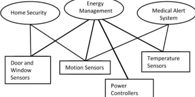
The home energy management application can be more cost-effective when allowed to use a sensornet deployed in an evolu-tionary manner. The home may have pre-existing wireless sensors deployed for a security application based on intrusion sensors on doors and windows, and motion detection sensors in indoor areas near the perimeter. The home may also have a temperature sen-sor used to control a cooling or heating system. At a later time, more motion or activity sensors may be added to the home in other indoor areas for monitoring the activity of a senior resident (such as for detecting disruptions to normal routine). The home energy management application can use many of these sensors to detect home occupancy and user activity. In addition to using the existing sensors, it may add new sensors to the deployment for measuring, visualizing, and controlling power usage.
In many existing sensornet usage scenarios, each application de-ploys its dedicated set of sensors. Each node is programmed with a sensor data collection, event detection, or query processing capa-bility and sends its data (sensor readings, events, query responses) to its user application using custom protocols and message for-mats [20, 27]. This mode of usage is not well suited for situa-tions where sensor nodes with different protocols, say from differ-ent manufacturers, may be added to a sensor deploymdiffer-ent over time. The custom protocols, new data types, and new functionality of the new nodes may not be exposed by the gateway. Adding new end-user applications to the existing deployment becomes difficult due to lack of direct access to sensor capabilities. An alternative will be to support the evolution of a sensing system and hardware with a common, well-understood application-level interface, so that all deployed sensors are available to all applications (Figure 1). As new sensors are added for new applications, existing applications may also benefit from the added sensors. Certain new applications that may not be cost effective to deploy with dedicated sensors may become feasible.
Door and Window Sensors Motion Sensors Temperature Sensors Power Controllers Home Security Energy
Management Medical Alert System
Figure 1: An example of evolutionary sensornet with sensors shared by multiple applications.
To support such system evolution, two fundamental features are needed:
Structured data: The first is that the data generated by the sensor nodes be represented in a structured format that any applica-tion may understand. For instance, data objects represented in XML may be read by any application while a custom bit representation requires a detailed documentation to interpret.
Programmatic description of functionality: The second feature is that the functionality of a sensor node be understood pro-grammatically. While a new sensor node added may auto-matically connect to the network using say DHCP and related methods, an application cannot use it until the functionality of the device is known. Programmatic access to sensor node functionality may allow a new user application to discover all sensors it may use or even allow existing application to add features as new sensor nodes are deployed.
As an added advantage, this could make end-user application devel-opment less prone to bugs since most of the message formats and packet exchanges can be programmatically and automatically gen-erated from the programmatic description rather than by manually reading the documentation for required bit sequences and message protocols for each custom gateway device format.
The above capabilities already exist for Internet connected de-vices and are available through web serde-vices: web method calls al-low structured data objects to be exchanged with remote resources and the web service description enables programmatic ways to ex-press the device functionality. The keychallengewe must address in using such an approach for sensornets is the minimization of re-source cost for providing structured data formats and functionality descriptions at the sensor nodes. These resource costs are negligi-ble for wired nodes. However, for low-power wireless sensor nodes that run for years without battery replacement, all resources includ-ing bandwidth, processor capability, and the active duty cycle are very limited. In this case, it is not obvious if the additional data size and processing costs for such structured access can be supported.
Thegoalof this research is to quantify the resource costs of pro-viding structured and programmatic access to sensor nodes using web services, and to identify design options that minimize these costs and trade-offs between interface generality and resource ef-ficiency. We characterize the costs of using web services in sen-sornets, and describe our design choices for making these costs acceptable on a resource constrained wireless device. To support ease of programming, our design choices maintain compatibility with commonly used web service development tools.
To constrain our design exploration and implementation, we use
a prototype sensor node that we built using an MSP430 proces-sor and an IEEE 802.15.4 radio (Figure 2). The procesproces-sor runs at 6Mhz, contains 48k of ROM, and operates at power levels typical of many low-power sensor nodes designed for multi-year lifetimes. The radio provides a maximum raw data rate of 250kbps. We
im-Figure 2: The wireless sensor platform, with an MSP430 pro-cessor and 802.15.4 radio, for carrying out the experiments re-ported in the paper.
plement web services on the above low-power platform, using only 15.8kB of ROM space. The energy and latency overheads com-pared to sending the raw data in 802.15.4 packets are very small: the battery lifetime is reduced by less than 11% and the latency in-crease is only 23.09ms when transmitting a 40 byte message every 10 minutes.
Our research yields several important guidelines for efficient use of TCP/IP and web services on sensornets, including the use of persistent TCP connections, disabling delayed acknowledgments in TCP, and using link layer retransmissions. While traditional web service usage assumes that the server hosting the service is always on, we show how web services can be hosted in an energy efficient manner on duty cycled nodes that must enter a low power discon-nected state for long periods of time. We further discuss the proper choice of web service bindings and XML decoding for efficient im-plementation on sensors with very limited memory.
We use the home energy application to provide realistic require-ments and application constraints for an evolutionary sensornet, such as to obtain sample message types required, events generated, sampling rates, and other system constraints. Further, to test the application, we built prototype power sensor nodes that measure the energy used by an appliance (for up to 2kW) plugged into our sensor node. The sensor node doubles as an actuator and can turn the power to the appliance on or off as well, similar to the sys-tem in [19]. As a test case, we deployed the power sensor-actuator nodes in a home with wireless motion sensors and perimeter intru-sion sensors for a period of 12 days. Sample sensor traces from the deployment are shown in Figure 13. Using the sensor data, a sim-ple occupancy-based optimization algorithm was able to achieve a 7.2% saving in home energy usage. More details of the case study are in Section 6.2.
Thecontributionsof the paper are threefold:
1. Characterize the energy costs of various overheads associ-ated with using web services,
2. Enumerate the design options available and the associated trade-offs in implementing web services, indicating the most suitable choices for sensor nodes, and
3. Present our implementation of the web service approach us-ing only 15.8kB of ROM and<1kB of RAM.
While the home energy application is used as a concrete test case for this research, the device resource constraints for the sensor nodes used are representative of many other wireless sensor network de-ployments and our design is thus relevant to more general systems. The rest of the paper is organized as follows. Section 2 discusses related work. Section 3 discusses the relevance of web services to sensor networks. Section 4 discusses our design space explorations to optimize the operation of web services on resource-constrained sensor nodes. Section 5 presents the experimentally measured en-ergy and latency overheads of the proposed approach. Section 6 describes our prototype implementation, including our power sen-sor node, and the test deployment of the home energy management application. We discuss the objectives achieved by our design and some of the key open issues in Section 7.
2.
RELATED WORK
The use of XML-based structured data has previously been ex-plored in sensor networks in IRISnet [9]. However, XML was used to represent a logical view of the data available across mul-tiple sensor nodes rather than to expose sensor node functionality via web services. The implementation was focused on gateways and non-resource constrained sensor nodes such as video cameras. Our work focuses on the low-power sensor nodes and uses XML to support web services, enabling a very different set of features compared to [9]. Another effort, SensorML [29], provides descrip-tions of sensor systems using XML, focusing on the data formats and functions for a wide range of sensors. Our focus is on pro-viding structured data and programmatic access to functionality on resource-constrained nodes.
Web services have been prototyped on embedded systems [16, 17], though for devices with more resources than the low-power sensor nodes. The code size and memory footprints achieved there are an order of magnitude larger than the ones in our system. We discuss the key design trade-offs in achieving a reduced overhead implementation.
Another related web service implementation for devices is pro-vided in SOCRADES [8], a middleware architecture for building production processes on top of Devices Profile for Web Services (DPWS) enabled smart objects. Due the limitations of device ca-pability, DPWS is implemented on gateway devices. We imple-ment web services directly on resource-constrained devices using the Web Services Description Language (WSDL) [6] specification, eliminating the need for application layer gateways that may get tied to a custom format between the gateways and sensor nodes hampering evolvability.
Another closely related work is the support for network layer in-teroperability using TCP/IP in sensor nodes [10, 11]. Our paper focuses on the application layer interfaces provided through web services, and assumes that the network layer interoperability, us-ing the TCP/IP implementation from [10], is already available. We use IPv4 in our evaluation of network layer overheads and resource costs for web services. A newer version, IPv6, is now widely sup-ported and is expected to have greater overheads in terms of the number of bytes transferred and resultant number of packets. How-ever, efforts such as 6lowpan [21] provide methods to reduce those overheads. An implementation of 6lowpan for low power sensor networks is available [1].
Web services have also been built using UDP [7] instead of TCP, using SOAP encapsulation. However, UDP does not provide end-to-end reliability and in order to avoid re-inventing TCP like func-tionality at the application layer, our design uses TCP.
In hosting web services on power-constrained sensor nodes, we include support for sleep modes and duty cycled operation through
the use of event notifications. The use of events has been proposed for web services through the WS-Eventing [28] specification. We keep our design compatible with [28] to enable easy integration with web service based Internet applications.
We also explore the design advantages of compressing the XML-based structured data formats used in web services in order to re-duce their bandwidth and energy overheads. XML compression has been considered before [5, 2]. The compression ratios for sev-eral XML compression schemes are compared in [2] but most of those methods are not suitable for implementation on low-power sensor nodes. We discuss the relevance of such XML compression to low-power sensor nodes in Section 4.5.
Standards such as ZigBee1[30], Zwave, X10, and Echelon may also support interoperability of low-power devices. However, each of these standards is tied to a single physical layer standard and, these standards need application layer gateways to connect to the rest of the Internet. We focus on an alternative approach that is built on widely-used open standards such as TCP/IP and web services. The TCP/IP layer enables any two devices with IP-compatible phys-ical layers to communicate; while the web services layer enables an application to access resource-constrained devices using the same tools that are used for accessing other online services hosted on more powerful servers, without the need for application-layer gate-ways. We do not aim to provide an exhaustive comparison between our approach and other standards that enable device interoperabil-ity; rather, we provide an evaluation point that helps compare a web services-based solution to other standards.
3.
WEB SERVICES FOR SENSORNETS
To explain the relevance of web services for sensor networks, we briefly summarize the capabilities of web services and show their advantages for sensor networks.
3.1
Structured data and functionality
Web services provide a mechanism for distributed applications to use resources that are on remote devices in a manner similar to local resources. A typical usage scenario is that some functionality available on one server is exposed as a method call for applica-tions running on remote devices. The web service protocol stack internally creates and exchanges the appropriate network messages required for the call, and provides the returned data object to the calling application. The programmer does not have to be concerned with the network protocols, packet formats, or other low-level de-tails of the underlying network. For example, a weather server may provide a method to obtain temperature:Float temperature
= GetTemperature(string Location)and any
applica-tion, running on an Internet connected device, can call this method. To realize the above functionality, web services standards spec-ify two key components: portsandbindings. The ports represent the application layer functionality to be provided: method calls that the web service supports. The bindings specify which network pro-tocols are supported. For instance, if the data and arguments for the ports are carried in a SOAP [14] formatted packet, then the binding is said to be SOAP.
Both the ports and bindings for a web service are specified us-ing the web service description language (WSDL) [6]. The spec-ification of a web services is usually referred to as its WSDL de-scription. If the functionality of a sensor node is expressed using a WSDL description, it can simply be accessed using the specified method calls.
1Currently, only members of the ZigBee Alliance may implement
3.2
Advantages
The use of web services on sensor nodes goes beyond simply enabling a new format for packet exchanges. It has the following significant advantages.
The first key advantage is interoperability. Our approach enables sensor deployments to be shared across multiple applications in a very flexible manner. Not only does it improve the performance of existing applications due to more sensors being available, but also enables deploying new applications that may not be cost ef-fective to deploy if dedicated hardware is required. For instance, in the example shown in Section 1, once the sensors required for the security, medical monitoring, and energy management applica-tions have been deployed, it becomes inexpensive to add a home automation application.
Second, the use of web services improves the programmability of the system. The WSDL description of the sensor node can be au-tomatically parsed by high level language development tools such as Visual Studio and NetBeans IDE. The programmer only sees a high level language object with the appropriate methods. Using the sensor node in the application is as easy as calling the appropriate method calls of this object. The development tool and the protocol stack automatically generate the messages to be transmitted over the radio, receive the response, and simply provide the end result to the application. The programmer is no longer required to code multiple custom protocols.
A third advantage is the ease of integration with enterprise sys-tems through the Internet. Many network applications are already built using web services. If similar interfaces can be supported on sensor nodes as well, much physically sensed data can be incorpo-rated into the existing information technology infrastructures, en-abling cyber-physical systems with many new capabilities.
Fourthly, the approach of running web services directly on the device eliminates the need for providing multiple gateways con-verting between the custom message formats of each sensor manu-facturer and the applications.
In addition to the application layer advantages of web service based protocols, the use of IP for the network layer also provides many benefits, including ease of network management, use of DHCP based address assignment, and the ability to work with many PHY layers. The proposed 6lowpan specification reduces the IP over-head by over-header compression, and it also enables the use of sensor network-specific routing within the low power sections of a net-work to avoid the overheads of full scale IP routing on low-power nodes. Several routing protocols optimized for sensor networks have been developed and can be incorporated at the 6lowpan shim layer for routing. Several sensor network specific MAC layers have also been proposed and these can be implemented at the lower lay-ers without affecting the web services application layer specifica-tion.
It may be noted that the web service approach is meant to im-prove the interface between sensor nodes and end user applications. The programming of the sensor nodes themselves is not signifi-cantly affected and existing tools such as [26, 15] may be used. The only impact is that a web service interface is provided along with its WSDL description. Some of the methods provided may even result in the node communicating with other nodes for in-network processing. These messages may continue to be in custom formats since they are not meant for client applications but are only used in-ternally by a group of coordinating sensor nodes deployed together. The end result of such joint processing may be offered through the web service interface.
The many advantages of using the structured web service based approach come with a non-negligible resource cost. Conventional
wisdom calls for designing custom protocols that optimize message formats to the last bit for reducing communication energy over-heads for matching the resource constraints of sensor networks. The obvious question then is: are the resource costs of web ser-vice based interaction is acceptable?
4.
DESIGN SPACE EXPLORATION AND
IMPLICATIONS
To address the above question regarding resource costs, we ex-plore the design space relevant to supporting web services on sen-sor nodes. Compared to using raw data over the link layer, using web services involves overheads at three layers: the network layer (IP), transport layer (TCP) and the web service application layer. We address the challenges in each of these areas by first charac-terizing the overheads and then designing our system to minimize these overheads.
The feasibility of implementing TCP/IP on resource-constrained devices with limited code space has already been addressed in [10]. However, given the implementation, actually using it for hosting web services on sensor nodes leads to further challenges, in terms of the energy and latency costs of communication. For instance there is a'3000%overhead in message size when using TCP/IP. We discuss the design choices including the effective use of per-sistent TCP, link layer retransmissions and related options to mini-mize the TCP/IP overheads. Our optimizations achieve significant reduction in overheads, reducing the latency to a mere21ms for a TCP exchange, without loosing compatibility.
The web service layer introduces significant overheads in mes-sage size and processing complexity. Our goal is to keep the en-ergy and latency overheads to only what is needed for evolutionary and interoperable development. We optimize the operation of the web service layer by enabling the web service host sensor nodes to enter long sleep modes through the use of eventing. We also optimize web service message size overheads through efficient en-capsulations and reduce the processing overhead of parsing XML messages by exploiting sensor specific information.
4.1
Network and transport layer design
We use TCP/IP at the transport and network layer as it is a widely used protocol and will support communication with a large num-ber of applications. It has the added advantages of ease of net-work management using well-established tools, ease of interaction with existing IP based networks, and the better chance of adop-tion by a wider community. The TCP/IP standards were developed for always-on devices while sensor nodes must be duty cycled to achieve long battery lifetime. Any increase in the length of data transfers due to TCP/IP headers and control messages will lead to higher battery overheads. Effectively using these standards, even with an available implementation, is non-trivial.
To optimize our design and minimize these overheads, we char-acterize the latency associated with TCP/IP using the experimen-tal setup from Section 5.1. We useduIP [10] as our TCP/IP im-plementation on sensor nodes. We obtained various TCP/IP per-formance measurements presented below by applying appropriate TCP/IP options.
4.1.1
TCP/IP overheads
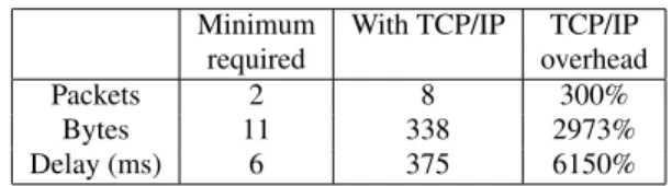
Consider a small amount of raw data (such as an event report with sensor values) to be transmitted, say 10 bytes. A conventional sensornet would transfer this data in a barebone 802.15.4 packet to reduce overhead. With TCP/IP, the packets must also carry 40 bytes of TCP/IP header. The minimum number of bytes required
for acknowledgment is 1 for the custom protocol while the standard TCP acknowledgment is used for TCP/IP. To examine the delay, message, and packet overhead associated with a TCP transfer, we capture network message timing for this communication, between a wireless sensor node and an application running on a PC.
Figure 3 shows the TCP message exchange and the timing cap-tured at the sensor node and at the PC. Table 1 shows the various overheads due to TCP/IP compared to sending data directly using 802.15.4 packets. We observe that the percentage overhead due to TCP/IP is extremely large. The number of bytes sent, the number of packets sent, and the total latency are affected significantly.
Minimum With TCP/IP TCP/IP required overhead
Packets 2 8 300%
Bytes 11 338 2973%
Delay (ms) 6 375 6150%
Table 1: Overhead due to TCP/IP compared to sending raw data (assuming raw data is 10 bytes and acknowledgment in the absence of TCP/IP is 1 byte).
Device PCTime ms Time ms 0 24 209 230 351 373 0 24 25 231 232 252 374 375
Figure 3: TCP Message exchange latencies.
4.1.2
Optimizations for sensor nodes
It is possible to optimize the operation without compromising interoperability with standard devices. We examine some of the techniques for reducing the above overheads below.
Persistent TCP connections.The overhead in number of packets required for a TCP transfer can be reduced using persistent TCP. A typical use of TCP connections is for two machines to estab-lish a connection, transfer some data, and terminate the connection. However, for a sensor node, all the web service-related communi-cation would be with a small number of applicommuni-cations using it. Here, it is much more efficient for the client application to maintain a per-sistent TCP connection with the sensor node and use it to transfer data as needed. With persistent TCP connections, from the previ-ous example (Figure 3), only 2 message transfers (message labeled
[PSH,ACK] DATAand the corresponding[ACK]message are
needed, resulting in a latency of(231−25) = 206ms. This reduces the delay, number of packets, and number of bytes associated with a TCP transfer significantly. The only overhead for persistent con-nections is the TCP heartbeat message, which is very infrequent. However, persistent TCP connections introduce one complication when implementing web services. Our web service implementation
makes heavy use of the HTTP protocol. In the older HTTP specifi-cation (version 1.0), a web server indicates the end of data transfer by closing the TCP connection. The current HTTP 1.1 specifica-tion [13] mandates that an HTTP 1.1 client correctly interprets the
content-length:field sent by the server to determine the end
of a HTTP transfer, and ending the TCP connection is not required to indicate end of transfer. However, if a client application states the older version in the HTTP request header, the sensor node will be forced to terminate the TCP connection after the data transfer, and the reduction in overheads possible through persistent TCP will not be realized. Device PCTime ms Time ms 0 24 45 45 72 0 23 25 48 68 73 75 46
Figure 4: TCP Message exchange latencies with delayed ac-knowledgments disabled.
Disable delayed TCP acknowledgments. The latency overhead after using persistent TCP can further be reduced by disabling the delayed acknowledgment feature of TCP. TCP uses cumulative ac-knowledgments; an acknowledgment for byte numbern acknowl-edges all the bytes up ton. Delayed acknowledgment feature uses the cumulative acknowledgment feature to reduce the number of messages sent over the network: after receiving a packet, the re-ceiver waits for one other packet before sending the acknowledg-ment. For every other packet received at a host, the TCP protocol stack starts a 200ms timer. If another packet is received before this timer expires, an acknowledgment is sent immediately. Other-wise, an acknowledgment is generated when the timer expires. This mechanism works well when a TCP connection is used to transfer a long sequence of packets. However, when sending a single message at a time over a persistent connection, the delayed acknowledg-ment feature causes an extra'200ms delay (the [209ms, 24ms] interval on the PC side in Figure 3) between sending of a message and the receipt of the acknowledgment. To reduce this delay, the TCP delayed acknowledgments must be disabled on both the host PC and the sensor node. Delayed acknowledgments is a TCP op-tion; hence, turning off delayed acknowledgments does not require changes to the existing TCP implementations. However in current TCP implementations, unlike most TCP options, delayed acknowl-edgments can only be turned off at a network interface or machine level granularity. If applying this option at such a coarse granular-ity is a concern, a gateway device can act as a proxy and have the delayed acknowledgment feature turned off. This can be achieved without knowing the exact nature of new sensor nodes that may be added after the gateway is installed. Essentially, the applica-tion layer is not using the gateway and hence no sensor-specific iunformation is used by the gateway; the gateway is only provid-ing a TCP connection. Figure 4 shows the same data transfer as in Figure 3, with delayed acknowledgments disabled on the PC side.
We observe that the combination of no delayed acknowledgments with persistent TCP connections results in a, much smaller delay,
(46−25) = 21ms, for transmitting the 10 byte payload and re-ceiving the corresponding acknowledgment.
Link layer retransmissions. TCP uses packet retransmissions to achieve end-to-end reliability of data. These retransmissions incur significant delays. For example, in Figure 5, when the packet num-ber 4 is lost due to a collision, that packet get retransmitted (packet number 5) only after a 2965ms delay. Such end-to-end retransmis-sion is less suitable for wireless links since packet loss probability is higher compared to wired links. Similar to the use of link-layer ARQs in commonly used in wireless standards such as 802.11, we can recover almost all packet losses using much faster link layer retransmissions without causing TCP timeouts.
Device PC Time ms 0 24 2989 3012 3034 0 2 21 2986 2989 3011 3013 3033 Time ms 24 3034 3055 3039 3041
Figure 5: TCP Message exchange latencies with TCP retrans-mission delay.
Low power mode between TCP messages.The energy overhead for keeping the radio on can be further reduced by turning off the radio in between TCP messages. From the timing diagrams in Fig-ure 3 and FigFig-ure 4, we observe that there is always some delay between a packet transmission and the corresponding reply. Al-though part of this delay will be random due to various network and application level randomness, there is a fixed minimum delay defined by the link capacities, hop count, and the packet size. If this delay is known, either through calculations or measurements, the battery-powered sensor node can safely sleep for this minimum period after receiving the link layer acknowledgment.
6lowpan. IPv6 is now being widely supported in many networks and this causes the network layer header size to increase beyond the overheads measured in our experiment above. In fact, the increased size of the header may even make the IPv6 packet too large to fit into a single 802.15.4 packet. The 6lowpan specification [21] pro-vides a way for IPV6 packets to be transmitted over 802.15.4, with mesh routing and shorter addresses. The reduced length addresses suffice for ensuring unique node addresses within a local sensor network in most cases. Also, 6lowpan uses a 8 byte header (includ-ingMesh Underheader) compared to the 20 byte header used in IPV4 enabling further savings. Thus, when IPv6 compatibility is needed, the sensor nodes may use 6Lowpan and a standard 6low-pan gateway for connecting them to the rest of the IPv6 network.
Link layer fragmentation. The 802.15.4 radio packet can sup-port a maximum of 127 bytes, including TCP/IP headers. With this
limited payload size, when a large amount of data needs to be sent over TCP, the data needs to be broken into multiple TCP segments resulting in increased message delivery times and power consump-tion. These overheads can be reduced using the link layer tation provided by 6lowpan specification. This link layer fragmen-tation enables us to take a large TCP/IP segment and break it into multiple 802.15.4 packets, which can be sent as a burst of packets to limit the message delivery delays and to reduce the packet retrans-missions byacquiringthe channel for the duration of the packet burst. The shorter delays and reduced packet retransmissions also reduce the energy consumption.
4.2
Supporting duty cycled nodes
Traditional web service implementations assume that the server hosting the web service is typically on and available. Battery-powered sensor nodes however, must enter low power modes to conserve battery and they cannot be reached when in the low power state.
There are two main techniques for interacting with a sensor or an actuator node – one in which the node is always ready to receive messages (the client application connects to the node as needed) and the other in which the node is event driven (the sensor node sends an event when the sensor detects some interesting change). Considering the example of the home sensor network previously described (Section 1), one may observe that some nodes, such as the power actuator nodes on lights or power sockets, the heating controller, or other actuators may need to be always ready to receive messages. Regardless of whether web services are used or not, these nodes will need to be reachable when required.
On the other hand, sensors such as PIR-based motion sensors, glass-brake detectors, door intrusion sensors, smoke detectors, and several others benefit from event driven operation. If web services are not hosted on the sensor node, it may easily turn off its radio and enter deep sleep state, periodically polling its sensor or waking up on an interrupt generated by the sensor, to reduce energy con-sumption. It would turn on the entire node and radio only when an event is detected. A large class of sensor nodes fall into this category and if web services are to be used on such nodes with-out causing excessive energy overheads, the ability to enter sleep modes must be supported. One possibility is to use the duty cy-cling at the MAC layer, similar to what is available in 802.15.4 and 802.11. However, such MAC layer solutions use short sleep durations to preserve the responsiveness of the node, while a typi-cal sensor that generates events has long inactive periods that can easily extend to several hours. Hence a MAC layer-based solu-tion with an acceptable response time can increase the node energy consumption, compared to a solution that enables the node to sleep between sensing events. We support duty cycled nodes through the use of web service eventing (WS-Eventing) [28]. With eventing, a sensor node hosting a web service can be in sleep mode for the entire duration between sensing events.
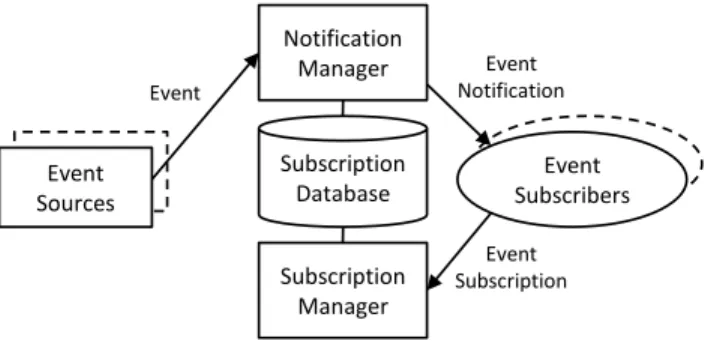
WS-Eventing describes five functional entities (Figure 6):
1. Event sourcesthat generate events (e.g. a smoke detector),
2. Event subscribersthat are interested in a particular event,
3. Asubscription mangerthat accepts and manages requests from subscribers,
4. An event subscription databasethat stores all active sub-scriptions, and
5. Anotification managerthat receives the original event and sends it to all active subscribers found in the database.
Event Sources Event Subscribers Event Sources Notification Manager Subscription Manager Subscription Database Event Subscribers Event Subscription Event Notification Event
Figure 6: Web Services Eventing architecture.
When implementing WS-Eventing in a sensor network, the sub-scription manager and the notification manager should be imple-mented on a gateway device that is always on, rather than on the sensor node itself, to reduce computational complexity and energy consumption. A single such device can handle event subscriptions and notifications for multiple sensors (a fail over device may be used to eliminate the single point of failure in the system). WS-Eventing specifies only the interface exposed by the subscription manager and the notification manager, while the format and the delivery mechanism of an event is left open (although an XML message describing the event is preferred). This implies that any sensor node that is designed with the specified event subscription and notification interfaces can be supported by the gateway. New devices may be added without changing the gateway. The sensor node could define its own events and send notifications containing data that is semantically relevant to the sensor node’s function. For instance, a smoke detector may generate events corresponding to smoke detection and low battery. To achieve the goal of structured data, our implementation encodes events in XML, and describes the events in the WSDL description of the sensor node.
4.3
Web service method encapsulation
As we described in Section 1, our web services implementation is centered around the WSDL standard. WSDL supports several encapsulation protocols for sending the method calls to the web service host device. Currently supported encapsulation protocols are SOAP, HTTP, and MIME. Thebindingsection of the WSDL file describes which one of these standards is used for accessing device methods.
Currently, SOAP is considered the de-facto standard for transfer-ring web service messages. However, a fully standards compliant SOAP server implementation requires considerable computational and memory resources than those provided by low-power proces-sors such as MSP430. The SOAP envelop is very verbose and also needs significant radio bandwidth. Referring back to the home sen-sor network example discussed earlier, two of the method calls used by the applications are listed in Table 2 along with the byte size for their SOAP encapsulations (two versions of SOAP are in common use and are listed). Both the processing complexity and the mes-sage size make the use of SOAP incompatible with the resource constraints of a sensor node. Most of these envelopes are too large to fit within a single 802.15.4 packet, and fragmentation will also worsen the communication latency.
However, SOAP provides much more functionality than what is required for accessing devices with limited functionality. A more lightweight approach for sending web service messages is to use HTTP. Since a standards compliant HTTP sever can easily be im-plemented on a resource-constrained processor such as an MSP430,
Method Name SOAP 1.1 SOAP 1.2 HTTP
GetTemperature 491 442 162
GetTemperatureResponse 479 499 258
SetTemperature(70) 528 482 202
SetTemperatureResponse 455 475 230
Table 2: Web service message sizes for different encapsulations.
HTTP binding becomes the ideal choice for sensor networks. Apart from the reduction in the computational complexity, the HTTP bind-ings also result in smaller messages (Table 2) due to the elimination of the relatively large SOAP envelopes from method calls.
The WSDL standard specifies multiple techniques for encod-ing method calls and call parameters within HTTP. The first one, called URL Encoding, maps the method call to a particular path within the HTTP server. For example, theSetTemperature()
method on the sensor with IP address192.168.1.4may map to thehttp://192.168.1.4/setTempURL. The URL en-coding technique for sending method parameters specifies a direct mapping between different fields (tags and parameters) in an XML document representing a method call and the parameters encoded in an HTTP GET request. The URL encoding method is identi-cal to the way parameters are passed in a URL using an HTTP query string when an HTML form is submitted with a GET request. For example, the SetTemperature(25) method can be en-coded ashttp://192.168.1.4/setTemp?temp=25. The second option, called URL Replacement, is similar to URL encod-ing except that instead of encodencod-ing the parameters in a HTTP query string, the parameters are mapped to the path of the HTTP GET URL. TheSetTemperature(25)method described above can be encoded as192.168.1.4/setTemp/temp/25. The third option is XML POST. In this approach, an XML formatted string is sent containing the method name and parameters, using HTTP POST. The sensor decodes the XML string and extracts the method parameters.
All the above methods are supported by the standard and the WSDL description of the sensor node’s web service can specify which alternative is used. The web service implementation on the host sensor node should use the URL encoding or URL replace-ment methods whenever possible. First, these techniques results in a smaller message size compared to sending a full XML mes-sage; second, the decoder for the URL encoding/replacement can be much simpler than for XML encoding. In section 5, we show that simple method calls can easily be encoded within a single 802.15.4 packet. However, if the method parameters are speci-fied within a complex XML message with varying number of el-ements (e.g. a variable length array), it may not be possible to specify a direct mapping from method parameters to a URL encod-ing/replacement, requiring a POST-based XML solution.
4.4
XML parsing on sensor nodes
XML parsing at the sensor node is only needed when URL en-capsulation does not suffice, such as for passing structured argu-ments. The overheads of implementing a general purpose XML parser are unlikely to be compatible with the resource constraints of a low-power processor. However, a key observation is that, when the device functionality is limited, the WSDL description only ex-poses a small number of methods and events. All messages that the sensor is required to respond to are created as specified in the WSDL description provided by the sensor. Clearly, the XML parser on the sensor can be designed to only parse the simple messages that it expects. Thus, simple text matching to search for the method
name and argument names suffices. Typically, the sensor node manufacturer who specifies the WSDL implements the parser. Al-though such a parser can be auto generated from the WSDL, we implemented a hand-coded custom XML parser on each device. The use of a custom parser remains transparent to the client appli-cations since they receive web service responses or events as spec-ified in the WSDL description and the sensor node remains fully compliant.
4.5
Compression and optimization
The XML format used for structured representation of data and methods was not designed for constrained sensor nodes and can be very verbose. There are several techniques that can be used to help reduce the message size increase due to XML. A first approach is to use compression. Either generic compression based on LZW algo-rithms, such as zip, or XML-specific compression methods (some-times referred to as binarization since they do away with the text representation) such as [5, 2] may be used. This approach does require a predetermined compression scheme be chosen and imple-mented by sensor nodes as well as a gateway node that connects the sensor network to rest of the network. The message size after compression is shown in Table 3 for generic (Zip) and XML spe-cific (XMLPPM) compression. A second approach is to optimize
Compression GetTemp. GetTemp SetTemp. SetTemp
Response Response Original 85 181 125 153 Xmlppm 65 98 85 92 Zip 114 157 138 151 Comp1 81 101 101 107 Comp2 26 46 46 53
Table 3: Sizes of request and response message payloads (ex-cludes encapsulation) with different compression schemes.
the XML format by replacing some the method names and argu-ment names that are defined by the sensor node, with very compact tags. For instance, the method nameGetTemperaturethat is 14 bytes (112 bits) may be replaced by single byte (allowing up to 28 tags within a single WSDL description). The XML node and element markers are left uncompressed for automated tools to continue working as before. For human readability, a dictionary that lists the mapping from the compact tags to the human readable method or parameter names may be provided. Table 3 also shows the compression achieved using this approach, labeled Comp1. A further variation, where in addition to the method names and pa-rameters, the common strings such as the XML header marker and namespace URL are also replaced with compact tags, labeled Comp2, is also shown.
Since the XML payloads in the sensor node method calls in our application context are relatively small, the use of Zip is not very efficient. The second approach of using compact tags is most ef-ficient. The tag mapping dictionary is retrieved only infrequently from the sensor node, similar to the access frequency of the sensor WSDL.
5.
EVALUATION
We implemented web services on a resource-constrained sensor node, using the design choices discussed in the previous section. In this section we evaluate the performance of the web services implementation, in terms of its communication, energy, and code-complexity overheads.
Detailed measurements reveal that for a variety of practical sce-narios, the overheads in energy and latency are very acceptable. For instance, for a sensor node generating one event every 10 min-utes, the reduction in battery lifetime is only 10.84%. The latency increase is within a few tens of milliseconds and is typically accept-able for most sensing applications. The measurements also reveal scenarios where the overheads may lead to significant performance degradation.
5.1
Experiment setup
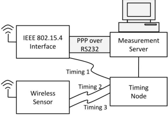
The evaluations require detailed visibility into the latency and energy overheads due to the increased message sizes, processing overheads, and increased number of packets due to the web service based approach. We use the setup shown in Figure 7 to measure the fine-grained timing behavior of communication over 802.15.4 radio links.
IEEE 802.15.4
Interface
PPP over
RS232
Measurement
Server
Wireless
Sensor
Timing
Node
Timing 1 Timing 2 Timing 3Figure 7: Experimental setup for evaluating network perfor-mance
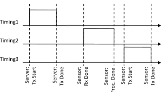
A measurement server is set up with an IEEE 802.15.4 network interface2. The wireless sensor used is our prototype node (Fig-ure 2) consisting of a MSP430F1611 processor running at 6MHz and a CC2420 radio. This node runs theuIP TCP/IP implemen-tation [10] along with our web service implemenimplemen-tation. To ob-tain packet transmission and processing delays, we disabled the random delays between the application’ssend()command and the start of CC2420 data transmission. We used a timing node consisting of a MSP430, wired to the server over USB, to collect timing of various events at the sensor node and the server’s wire-less interface. To obtain timing, we connected a wire, denoted as signal (Timing1), to the server’s wireless interface and 2 wires,
(Timing2andTiming3), to the wireless sensor. Figure 8 shows
the timing of the three signalsTiming1. . .Timing3: the server’s wireless interface asserts theTiming 1signal when it starts send-ing a radio packet, and clears it when the packet transmission is fin-ished. The wireless sensor asserts theTiming2signal on receiv-ing a radio packet, and clears it after processreceiv-ing the packet. The sensor assertsTiming3when it starts sending a packet, and clears it after the packet is sent. The difference between,Timing1and
Timing2represents the time taken by the sensor to decode and
as-semble the packet in the radio module. To obtain accurate timing,
2The 802.15.4 interface is a MicaZ mote connected on the serial
port at 115200 baud, using the PPP [25] protocol. A local IP sub-net is implemented over this PPP connection, bringing the packets received on the radio to the server’s TCP/IP stack.
Server: TxSt art Server: TxDo n e Se n so r: Rx Don e Se n so r: Pro c. Don e Sen so r: Tx St art Se n so r: Tx Don e Timing1 Timing2 Timing3
Figure 8: Communication activity timing in the experiment set up.
the timing node used a temperature compensated clock source run-ning at 6MHz. To capture timing at the server, the Wireshark packet sniffer was used. A single run using this setup produces an output of the form shown in Table 4. This sample output also shows that the packet processing times on the sensor, that include the web ser-vice method call parsing and the TCP/IP stack processing, are very small: for the first packet the processing time is10.67−9.68 = 0.99ms and for the second one, it is36.35−35.53 = 0.82ms.
Time (ms) Event TCP Action 0.00 Server Tx start TCP data 6.19 Server Tx done (74 byte request) 9.68 Sensor Rx done
10.67 Packet processed
10.68 Sensor Tx start TCP ACK 11.71 Sensor Tx done
29.29 Server Tx start TCP data 33.35 Server Tx done (27 byte request) 35.53 Sensor Rx done
36.35 Packet processed
36.36 Sensor Tx start TCP data 37.78 Sensor Tx done (37 byte reply)
Table 4: Message communication and processing times.
5.2
Energy cost
The use of TCP/IP and structured XML data for web services increases the message sizes and hence the energy consumption at sensors. The increased energy consumption reduces the battery life. In this section, we examine the impact on battery life due to web services. Suppose the application wishes to transferxbytes of pay-load. A barebone protocol can send this data directly over 802.25.4 packets with no additional headers, while the web service approach does involve the TCP/IP and encapsulation headers. For encapsula-tion, we use HTTP 1.1 that has request and reply headers of 21 and 37 bytes respectively. We varyxfrom 1 to 80. Payload sizes for example methods in our prototype (Table 3) lie in this range with XML optimization. With web services, whenxis increased beyond 53 bytes, two packets are needed to transmit the complete request (due to TCP/IP and HTTP headers) while in the barebone case one packet suffices. As discussed in section 4, we use persistent TCP connections and disable TCP delayed acknowledgments.
For the energy numbers, we use a MSP430F1611 processor run-ning at 5MHz (internal DCO) consuming'3mA when active, and 2µA during sleep, and a CC2420 radio that consumes 18.8 mA in receive, 17.4 mA in transmit (0dBm output power), and 0.02
µA in sleep modes. Timing is measured using the experimental setup from section 5.1. We use this timing to compute the power consumption and the resultant battery lifetime assuming two AA (2200 mAh) batteries. The battery self-discharge for typical alka-line batteries is used: '3% loss of capacity per year due to self discharge [3]. With timetexpressed in years, this yields the capac-ity,c(t)at timetas: ct = c0e−t×ln(0.97)wherec0 is the initial
capacity. The battery is assumed dead when the voltage falls to 1.05V (corresponding toc(tdead) = 400mAH, using the battery
discharge curve) from the initial 1.5V.
Figure 9(a) shows the battery life assuming that the radio is turned off during the gaps between TCP message transmissions, and Fig-ure 9(b) shows the battery life if the radio is kept powered on (re-ceive mode) during the whole TCP transfer, for both the web ser-vice (WS) and the barebone approaches. The three curves represent three application scenarios requiring one message every 1 minute, 10 minutes, or 100 minutes. 0 20 40 60 80 0 5 10 15 20 25 30 35 Payload (Bytes) Lifetime (years) Barebone (1 min) WS (1 min) Barebone (10 min) WS (10 min) Barebone (100 min) WS (100 min)
(a) Radio Off Within Transfer
0 20 40 60 80 0 5 10 15 20 25 30 35 Payload (Bytes) Lifetime (years) Barebone (1 min) WS (1 min) Barebone (10 min) WS (10 min) Barebone (100 min) WS (100 min)
(b) Radio On For Entire Transfer
Figure 9: Battery life variation with client request size.
We observe that incremental cost due to different message sizes is comparatively small compared to the total battery life, when the complete message can fit inside a single packet. When a message is sent every 10 minutes, the reduction in lifetime is 4.74% at a request size of 40 bytes, and with the radio on for the entire TCP transfer, the reduction is 10.85%. The reduction becomes more significant with very frequest message exchanges, such as once ev-ery minute are considered, but such high rates are less likely to be needed. In our prototype deployment of the home energy man-agement application over 12 days (Section 6.2), we observed that sensor states for door intrusion sensors, motion sensors, and power sensors changed only 2 to 20 times a day, keeping the event genera-tion rate between once every 100 minutes to once every 10 minutes. Also, while at high message rates, there is a significant impact on
lifetime when the request splits into multiple packets under the web service approach, the impact becomes negligible at more practical message rates.
In summary, we observe that the incremental cost of using web services is not significantly higher than the barebone protocol. The comparisons made above in fact give an unfair advantage to the barebone protocol. In the above evaluation, we assumed there are no overheads due to message retransmissions, carrier sensing de-lays, link layer acknowledgments, or radio wake-up schemes. The communication was assumed to be synchronized so that radios were turned on only during active communication. In practice, such packet losses and retransmissions will occur and even the barebone protocol usage will involve some overheads in waking up the next-hop nodes before transmission. When such overheads are included in the comparison, the incremental overhead of web services would be even smaller.
5.3
Response time
In certain time-critical sensor network applications, such as those involving human interaction, the response time of the system be-comes very important. Consider as an example the time to turn on a lamp when a home automation application on the user’s cellphone sends a turn-on request. While web service overheads are accept-able for most of the network links, the latency increase on the last leg involving 802.15.4 links to the sensor is a concern. Assume for such applications that the wireless sensor/actuator is already on. The lamp power actuator in the previous example may stay on by using power from the wall socket. The wake-up overheads, if in-volved, would be similar for a barebone protocol or the web service approach.
The response time depends on the time taken to complete a web services method call. We measured the response time for varying web method request sizes, using the setup from Section 5.1. Fig-ure 10 shows the results. We note that the response time is not significantly affected by the request size as long as the request can fit in to a single IP packet (53 bytes of request payload). For a 40 byte payload at an average message rate of once every 10 minutes, the latency increase is only 23.09ms.
The delay is a few tens of milliseconds, even when the request breaks up into two packets. There is a potential to reduce the de-lay increase when the payload splits across multiple packets even within the web service based approach. The delay increases sharply because the TCP/IP stack fromuIP used in our prototype sends and acknowledges each packet individually. Schemes such as frag-mentation and reassembly at the link layer (Section 4) or sending multiple packets without having TCP wait for individual packet ac-knowledgments can reduce this delay in case of larger web method requests. 0 10 20 30 40 50 60 70 80 0 10 20 30 40 50 60 Payload (Bytes) Response Time (ms) Barebone WS
Figure 10: Response time for comparison.
6.
PROTOTYPE IMPLEMENTATION AND
DEPLOYMENT
In this section, we demonstrate the use of our web services solu-tion to support an evolving sensor network deployment in the con-text of a home energy management application. We also show that the ROM space required by our prototype implementation for host-ing a power sensor web service on a low power sensor is only 15.8k, including the XML parser, HTTP server, and the TCP/IP stack. We also present the design of our power sensing and actuating node along with a 12 day deployment of the home energy management application.
6.1
System description
We implemented web services on a resource-constrained plat-form using an MSP430 processor and an 802.15.4 radio (Figure 2). A central controller was implemented on PC with a 802.15.4 net-work interface. Figure 11 shows the block diagram of our imple-mentation.
The components shown in the figure are described below:
Sensors:Each sensor node contains two WSDL files that describes the WSDL ports and binding:dev.wsdl, specifying the method calls supported by a device, and bindings.wsdl, specifying how the methods are encapsulated and transported. The informa-tion in dev.wsdlcompletely describes the method names, pa-rameter names, and the data types of the papa-rameter and return val-ues. Thebindings.wsdlWSDL file imports thedev.wsdl, makingbindings.wsdlthe complete WSDL description of the sensor. For devices that generate events, bindings.wsdl in-cludes three additional methods, and a separate Port type. Two of these methods,void eventOn(string eventName)and
void eventOff(string eventName)are used for enabling
and disabling specific events; the other methodvoid
setHandlerURL(string url) sets the URL to which the
events are posted. These three methods are only accessible by the
Controllerwhile the methods defined indev.wsdlare accessible to applications. As described in section 4,bindings.wsdluses HTTP bindings with URL encodings for method calls, and XML messages for return values. The sensor runs an HTTP server for accessing WSDL files and for calling device methods.
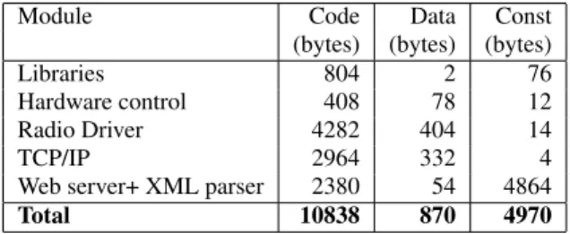
Table 5 shows the RAM and ROM storage requirements for im-plementing web services on the power sensing node, including the storage for the WSDL files. The column labeled ‘Const’ represents the constants stored in ROM. As the table shows, the device
imple-Module Code Data Const (bytes) (bytes) (bytes)
Libraries 804 2 76
Hardware control 408 78 12 Radio Driver 4282 404 14
TCP/IP 2964 332 4
Web server+ XML parser 2380 54 4864
Total 10838 870 4970
Table 5: Power sensor memory usage.
mentations can easily fit inside a low-power processor such as the MSP430. The two WSDL filesdev.wsdlandbindings.wsdl
are large: 2.7kB and 1.3kB respectively. However, this is not a ma-jor concern since they are accessed only very infrequently, for pop-ulating the controller’s internal state as described in the following sections.
Sensor Registrar:The registrar is responsible for registering new devices with the controller. In our current implementation, a user
HTTP Server/Proxy Device Info. Eventing Info. HTTP Client Registration Info. HTTP Server dev.wsdl bindings.wsdl
Sensors
(Web Service hosts)
Sensor Registrar
Controller
Client
Applications
Home Energy
Management
Figure 11: Block diagram of web services implementation for sensor networks.
enters a pre-assigned device IP address and a user-friendly device name using a GUI. Future work includes supporting DHCP-based address assignment and exchanging a secret key for link layer se-curity. Once a sensor is registered, the registrar accesses the device and downloads the two WSDL files. It combines these two WSDL files, the user-friendly name, and the device IP address into a sin-gle XML file and uploads it to the Controller. Although currently implemented on a PC, registrar and the controller may be imple-mented on a device such as an 802.15.4 access point or a set-top box.
Controller: The controller acts as the central entity that bridges the sensor network and the client applications that wish to use the sensors. The controller acts as an HTTP server for registering new devices and for accessing the currently registered list of de-vices. When a client application or a web browser, accesses the
http://Controller/index.htm, the Controller dynamically
generates an HTML page listing the currently registered sensors. Each sensor’s listing also includes a link to a sensor WSDL descrip-tion of the formhttp://Controller/wsdl/<sensorName
>.wsdl, When the sensor WSDL link is accessed, the Controller
uses the sensor’s stored WSDL files to dynamically generate a new WSDL file with SOAP bindings, in place of the original HTTP binding in the sensor’sbindings.wsdl.
The SOAP bindings allow additional SOAP-based functional-ity to be supported on connections between the Controller and the client applications. For instance, the client applications may be running on a device connected to the home through the Internet, and the security features of SOAP may be used for authenticating this access. Note that the conversion of bindings does not require sensor specific knowledge, and can be performed for old or new sensors added to the system. This conversion also has a side effect that some web service development tools that only support SOAP bindings can also be used by the client application developer. When a client application calls a sensor’s method using SOAP, the Con-troller intercepts the SOAP message, extracts the method name and method parameters, and sends them to the sensor using HTTP bind-ings. If the call is successful, the controller encapsulates the XML file returned from the sensor within a SOAP message and returns the SOAP message to the application. If the call fails (an HTTP er-ror message is received), the Controller returns a SOAP fault. The Controller also implements the event subscription manager, sub-scription database, and notification manager required for eventing (Figure 6). When an application subscribes to a sensor event, the
Controller updates its subscription database and itself subscribes to this event by using the sensor’s event subscription method call. Whenever the sensor generates the event, the Controller (being also the notification manager) distributes the event to all client applica-tions that have subscribed to it.
The sensor may enter a low power state with its radio turned off after receiving a threshold number of event subscription requests, assuming some applications are using the data it generates. It will now turn on its radio only to transmit events when generated. If more applications wish to call any of the web service methods on the sensor, the Controller must wait for the sensor to wake up and then send the method call to it. Since this can have a significant delay, client applications may benefit from using the asynchronous mode for a sensor’s web service method calls. Our current imple-mentation does not support this functionality yet. The Controller can use methods such as repeated beaconing [24] to wake up sen-sors or simply wait for the sensor to wake up at a scheduled time for achieving this functionality.
Client Applications: The client applications are end user appli-cations that use the sensor network through the web service in-terfaces. They call the methods exposed by sensors using SOAP method calls to the sensor’s web service address as provided by the Controller-generated sensor WSDL description. Web services de-velopment environments such as Visual Studio and NetBeans IDE can automatically parse the WSDL description to generate a high level language object, such as a Java object, that represents the web service on the sensor. The application developer simply calls the methods of this object to use the sensor. The developer only needs to know the semantics of the sensor, such as how to use the sensor data (for instance, temperature may be used to control the heat-ing), but does not need to read any detailed documentation about how the arguments required to be sent for a particular functionality are represented in a bit sequence or what is the sequence of packet exchanges required. The client application in our system, home energy management, and its deployment are discussed in the next section.
6.2
Home energy management application
As an example of an evolutionary sensor system we present a home energy management application that uses sensors that are typically deployed for other home sensor networking applications such as security and medical alerts. The energy management appli-cation adds a small number of new nodes in the existing network.
The new nodes are power sensors that provide the capability to both measure the power drawn by the appliance plugged into it and to power on or off that appliance. The application also includes a GUI that lets a user manually control the power actuators or visualize the energy usage of appliances plugged into our power sensors.
Electronic Switch (TRIAC) Power Meter (ADE7757) Current Sense Resistor Radio + Processor Module Power Voltage Sense NEUTRAL NEUTRAL LIVE LIVE
Power IN Power OUT
Figure 12: The smart-socket block diagram.
The sensor platform used is our prototype shown in Figure 2. We also built the power sensor-actuator node, denoted a “smart-socket.” A block diagram of the smart-socket is shown in Figure 12. The smart-socket plugs into an existing wall power socket and pro-vides another socket to plug in the appliance. Our design supports appliances up to 2kW which is sufficient for most typically used lamps, home entertainment electronics, home computers and net-work equipment, and kitchen appliances. The measurement and vi-sualization of power consumption is known to be useful for saving energy [23] the smart-socket may be used in an energy visualiza-tion system to help users reduce their carbon footprint. Our home energy management application goes one step further and uses the smart-sockets in conjunction with other sensors in the home to au-tomatically reduce energy usage.
We deployed the power and motion sensors in a volunteer fam-ily’s home for a period of 12 days. Smart-sockets were deployed on most-used entertainment electronics and lamps. To represent the evolutionary deployment, we assumed that a medical alert applica-tion has already deployed moapplica-tion sensors in the home (we built these by interfacing an off-the-shelf motion sensor [22] to a Te-los mote). Motion sensors were deployed in the living area, study room, and each bedroom. To represent the sensors deployed as part of the security system, we obtained the data from the same home’s security system. This system had an on-line interface exposed by its monitoring company’s website that allows downloading secu-rity sensor data. Sample traces from a motion sensor in the living area, the main door security sensor, and a smart-socket connected to a dim-able lamp are shown in Figure 13. The time axis details are omitted to protect the volunteer family’s privacy. The home en-ergy management application uses the data from multiple sensors to determine whether the home is occupied, and which room is the one occupied. This information can be used to save energy spent on heating, home electronics, and lighting by turning off devices when not required.
Energy Savings:To illustrate the usefulness of the evolutionary approach, we use the motion activity to control the heating. The en-ergy savings achieved by the evolutionary application are shown in Figure 14. Total reduction in heating energy was7.2%3. Energy is
0 2 4 6 8 Time Motion Events
(a) Motion sensor, partial trace
0 100 200 300 Time Power (W)
(b) Power Sensor, partial trace
0 0.2 0.4 0.6 0.8 Time
Door Open Events
(c) Security sensor, partial trace
Figure 13: Test case: sample data from a deployed home energy management system. 2 2.2 2.4 2.6 2.8 3 3.2 3.4 3.6 3.8 1 2 3 4 5 6 7 8 9 10 11 12 En e rg y ( th e rm s) Time (Days) Static Energy Saver
Figure 14: Savings achieved by adding an energy management application to a home sensor system.
saved by setting the desired temperature to a lower value when the home is not occupied. The algorithm aggregates the motion output from all motion sensors to determine home occupancy status and sets the indoor temperature to a lower value. Since the furnace in the deployment home was not interfaced to our sensor network we experimentally measured the home’s heat loss model4and the heat-ing furnace energy usage. The energy savheat-ings were then computed
3
The monthly gas consumption was 90.8 therms and these savings with the local energy price convert to USD 8.44 per month.
4