neuronal layers implementation using a common digital bus multiplexed in time, the AER bus. This representation assigns a unique digital word (address) to each neuron.
One of the main advantages of this neuromorphic approach is the fact that the process to perform does not need to be delayed until all the input data needed is gathered, as it occurs in classical artificial vision systems where any processing step needs to wait to have a complete frame or picture in memory. When using adequate neuromorphic sensors, the sensed reality is translated into a sequence of spikes or events. These events represent those pixels that have detected a change (i.e. luminosity change, edges in a moving object..., etc.) with the presence of the pixel address on the AER bus and quantizing the intensity of the detected change with a larger or smaller stream of events. The potential of this approach allows the implementation of pseudo-instantaneous preliminary results of complex processing algorithms [17]. Their FPGA implementations are being a very popular and attractive way to demonstrate these properties of neuromorphic systems from sensors to robotic actuators [8][13][14][15][16].
Classical control approaches of degree-of-freedom (DoF) actuators in robots use Proportional-Integral-Derivative (PID) controllers where the error signal is the source of the controller. There are two spike-based controllers [13][14], where spikes are used to directly power the motors, which considerably reduces power and latencies between the decision taken and the change in the motor. These two works can be used in the ED-Scorbot as IP cores for FPGA: a translation of a classic PID to the spikes domain, and a neuro-cortex inspired controller (described in section IV).
This paper presents the ED-Scorbot neuromorphic robotic framework as a test bed for cognitive robotic algorithms. The framework was born during the BIOSENSE project and it is intended to be used by the neuromorphic community researchers locally or remotely. It is mainly composed of hardware components (robotic arm, event-based sensors and FPGA-based AER boards), and a library of IP cores for FPGAs for event-based sensor’s filtering /processing /fusion and spike-based motor controllers. Computer interfaces are supported in jAER [12]. The next section reviews those sensors that are compatible with this framework. Section III summarizes sensor’s processing IPs for FPGA. Section IV is devoted to motor controllers IPs. And section V describes the platform with details.
II. EVENT-BASED SENSORS
This section reviews and summarizes the two main sensors initially available in this framework, although any other could be adapted with little effort.
ED
-
Scorbot: A Robotic test
-
bed Framework for FPGA
-
based
Neuromorphic systems
F.
Gómez-Rodríguez, A. Jiménez-Fernández, F. Pérez-Peña, L. Miró, M.J. Domínguez-Morales,
A.Ríos-Navarro, E. Cerezuela, D. Cascado-Caballero, A. Linares-Barranco
Abstract— Neuromorphic engineering is a growing and promising discipline nowadays. Neuro-inspiration and
brain understanding applied to solve engineering
problems is boosting new architectures, solutions and
products today. The biological brain and neural systems process information at relatively low speeds through small components, called neurons, and it is impressive how
they connect each other to construct complex
architectures to solve in a quasi-instantaneous way visual and audio processing tasks, object detection and tracking, target approximation, grasping…, etc., with very low power. Neuromorphs are beginning to be very promising for a new era in the development of new sensors, processors, robots and software systems that mimic these biological systems. The event-driven Scorbot (ED-Scorbot) is a robotic arm plus a set of FPGA / microcontroller’s boards and a library of FPGA logic joined in a completely event-based framework (spike-based) from the sensors to the actuators. It is located in Seville (University of Seville) and can be used remotely. Spike-based commands, through neuro-inspired motor controllers, can be sent to the
robot after visual processing object detection and
tracking for grasping or manipulation, after complex visual and audio-visual sensory fusion, or after performing
a learning task. Thanks to the cascade FPGA
architecture through the Address-Event-Representation (AER) bus, supported by specialized boards, resources for algorithms implementation are not limited.
I. INTRODUCTION
Neuromorphic systems currently provide a high level of parallelism, interconnectivity, and scalability, carrying out complex processing in real time, with a good relation between quality, speed and resource consumption. Neuromorphic engineers work in the study, design and development of neuro-inspired systems, like analog VLSI chips for sensors [6][1][7], and neuro-inspired sensor’s processing, filtering and learning [2][3][4][8][9], among others [5][13][14]. Signals in spikes-domain are represented by short pulses in time (i.e. spikes). Information is carried by spikes, and it is usually measured in spike frequency (following a Pulse Frequency Modulation (PFM) scheme), inter-spike-interval timing (ISI) [3], time-from-reset to a spike, spike rate or other higher level modulations.
Address-Event Representation (AER), proposed by Mead lab in 1991 [10][11], solved the problem of connecting silicon neurons in hardware along chips, to allow different Francisco Gómez-Rodríguez, Angel Jiménez-Fernández, Lourdes Miró, Manuel J. Domínguez-Morales, Antonio Ríos-Navarro, Elena Cerezuela, Daniel Cascado-Caballero and Alejandro Linares-Barranco are with the Robotic and Technology of Computers Lab. Higher Polytechnic and Computer Engineering Schools. University of Seville, Sevilla, SPAIN (emails: {gomezroz, ajimenez, lmiro, mdominguez, arios, ecerezuela, danic, alinares}@atc.us.es). Fernando Pérez-Peña is with the Applied Robotic Lab University of Cadiz ([email protected]).
Dynamic Vision Sensors [6] mimic part of the biological retina’s functionality in silicon chips using typically CMOS circuits in weak-inversion regions with asynchronous communications (AER) [10][11]. Each sensing unit or pixel is equivalent to the ON and OFF bipolar cells after the cones of a biological retina. They work independently of each other, they sense incoming visual information and then they send events that codify its (positive and negative) changes, like an increment or decrement in luminosity. These sensors send out the visual information with a small latency, due to the circuitry itself. A sensed change is sent out in the precise instant it is produced. This philosophy is radically different to the one in artificial vision. All digital cameras work by measuring reality for a short period of time (exposure time) and then they spend a considerable amount of clock cycles sending out a whole picture or frame, even though only a few pixels have changed since the last frame captured. For hard real-time systems, such as mobile robots or high-speed manipulation, this biological mimicking approach is crucial and it is allowing nowadays the development of embedded systems working with visual information that are able to perform relatively complex visual tasks, like fast object detection and tracking [15]. Several groups have developed similar sensors, but the operational principle is the same, like ATIS/cnmDV [6]. There are other kinds of event-based analog sensors, like cochlea [1] and olfactory ones [7].
The biological cochlea is a part of the inner ear that plays a central role in hearing. It moves in response to vibrations caused by sound signals entering the ear and making the basilar membrane vibrate. Thousands of hair cells on the membrane sense the vibration and excite the spiral ganglion cells, which generate spikes that are sent to higher-order auditory brain areas. Because of the physical properties of the basilar membrane, high-frequency inputs activate the basilar membrane area closest to the base of the cochlea, while low-frequency waves travel further down the membrane [19]. The first silicon cochlea was proposed by Lyon and Mead [20] with a cascade of 480 second-order filter sections. In biological cochleae, the acoustic wave is filtered mechanically and its frequency components are represented by neural pulses in the auditory nerve. In this robotic framework, we use a novel way to process the sound wave using Spikes Signal Processing (SSP)[25].
We use two spiking audio systems for FPGA: the Neuromorphic Auditory Sensor (NAS) for FPGA and a
spiking digital-filter-based cochlea. The NAS transforms the information in the acoustic wave into an equivalent spike rated representation, and then it uses a bank of cascaded spike-based low-pass filters, which is inspired on Lyon’s model of the biological cochlea [18]. This auditory system processes information directly encoded as spikes using Pulse Frequency Modulation (PFM), decomposes PFM audio into a set of frequency bands, and propagates that information by means of an AER interface (see Fig. 1).
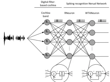
The spiking digital-filter-based cochlea for FPGA has been implemented together with a spiking neural network for Spanish commands recognition (Fig. 3) [27]. The frequency-selective displacement characteristic of the basilar membrane is modelled using an array of 21 band-pass digital filters and a set of spike generators. The band-pass filters, whose cut-off frequencies range is over the human speech frequencies (20 Hz - 20 KHz), split the speech signal into different frequency components. It is based on the subdivision of the audible frequency range into critical bands proposed by Zwicker [28]. Each digital filter is connected to a spike generator [29] that mimics the functionality of the inner hair cells (IHCs).
III. EVENT-BASED SENSORY PROCESSING
Fig. 2 shows the architecture of the logic for multiple objects detection and tracking for this framework. It is composed of two main blocks: the background activity filter (BAF) and the object tracker with center of mass calculation (CMCell), where the second one is replicated several times in a concatenated way.
A. Background Activity Filter
The ON/OFF bipolar events of dynamic vision sensor, which represent the temporal contrast changes (DVS events), are processed firstly by a Background Activity Filter (BAF) to remove all the non-spatially and non-temporally correlated event-rate activity. These DVS chips usually send sporadic events due to noisy currents not related to light changes in their pixels. This activity can decrease the performance of any processing. BAF uses an always-on 32-bit timer for time measuring.
B. Event-based Tracker
This logic has to detect a potential object from DVS output and it then has to follow the object in the visual field. To accomplish this, the implementation used for this framework waits for an object at a particular initial position
Analog Audio AC’97
Audio Codec AC’97 FSM L – NAS Filter Bank (L-NFB) L - Synthetic Spikes Generator .. . BPF_L_HF BPF_L_LF R – NAS Filter Bank (R-NFB) R - Synthetic Spikes Generator .. . BPF_R_HF BPF_R_LF L-Data R-Data AC’97 FPGA AER Monitor AER REQ ACK ... Spikes_L_0 Spikes_L_N Spikes_R_0 Spikes_R_N ...
Digital Audio Spikes
20
20
Right Left Analog Audio
Fig. 1: NAS Architecture. From left to right: analog audio signal is digitalized through commercial AC’97 audio codec. A FSM on the FPGA split left
and right signals into spikes generators. These spike-streams are processed by two cascade SSP filters that decompose audio into channels or bands in
and sub-window of the visual field, called cluster. This initial cluster location and size are configurable parameters. As soon as a number of events, N, fall into the cluster within a configurable period of time, the tracker is said to have detected an object. A configurable extension over the cluster size is always monitored by the tracker for dynamic decision making on cluster size and position updates. Even N can be dynamically updated for automatic adaptation to different object speeds. Depending on the evolution of next events falling in the cluster several tasks are performed in parallel: (1) position update through the visual field according to the CM calculation of last N events. (2) Cluster size update (enlarged or shrunk) depending on the presence or absence of events both in the cluster and its extension. If there is activity in this extension area the cluster is enlarged. If the activity is concentrated around the center of the cluster then it is shrunk. (3) Current CM can be averaged with the number of the last CM events (only a power of 2 for simple implementation) to low-pass-filter for smoothing changes in the trajectory. (4) N update: if the last N events have been detected in a very short period of time (i.e. the object speed is increasing), N is increased; but if that time for receiving N events is increased (i.e. the object speed is decreasing), then N is decreased to reduce the latency in the CM calculation (precision can be reduced).
Each of these trackers in the FPGA has one input and three different outputs: CM events, cluster events and pass through events. The latter sends out all the events that are not falling into the cluster of the current tracker, so this output represents the output of the DVS where all the events of the first detected object have been filtered. This output is used by the next tracker for detecting a new object in the visual field. The number of trackers to be implemented is only limited by the resource limit of the selected FPGA.
C. Acoustic frequency bands classification
The AER output of the NAS codifies the frequency activity of the sound. Each address corresponds to the mid frequency of a band-pass filter. Different channels output must be properly correlated in order to detect or classify different acoustic features like pure tones, musical notes,
vowels, etc. Spiking neural networks for SpiNNaker have demonstrated good accuracy [24], but simpler convolution filters for FPGA (with properly adjusted / learned weights) have also demonstrated good results [26]. The ED-Scorbot framework has the convolution-based approach available (as an IP core), although SpiNNaker platforms could be easily connected to the framework for cognition task improvement.
D. Words recognition
A spiking neural network is used for detecting phonemes and words, as sequences of phonemes. It is composed of three types of neurons: Recognition-neurons (RNeuron) spike when a set of their inputs spike simultaneously and when a pre-set pattern is detected in their inputs; Winner-neurons (WTANeuron) are used for empowering the most active RNeuron and depressing the rest [32]; and Delay-neurons (DelayNeuron) are needed for detecting commands such as sequences of phonemes. These neurons, which are based on an integrate and fire model [30][31], are able to recognize auditory frequency patterns, such as vowel phonemes.
E. Sensory fusion and integration
Sensory fusion is understood as a trained technique that is able to use a mixture of the information from both types of sensors in order to properly classify different scenarios. Usually, neural networks and deep learning approaches have been used for that purpose. Sensor integration is a term devoted to those techniques that make different approximations for a decision separately with different sensors, which are then combined statistically for the final decision. The IP library of this framework includes a sensory integration module [23]. The sensory fusion for FPGA in terms of an IPcore is currently being tested.
IV. EVENT-BASED MOTOR CONTROLLERS
The IP library of the ED-Scorbot framework also includes two motor controllers implemented in the spike domain: a classic approach of a PID controller (SPID) and a motor-cortex based on the Vector-Integration-To-Endpoint (SVITE).
A. SPID [13]: In control theory, a closed-loop controller compares the real system state with a desired one, getting the system error. This system error is processed, and then applied to the system under control. A classic controller is the Proportional-Integral-Derivative (PID). This controller calculates three components: (1) one is Proportional to the system error; (2) another one is proportional to the temporal Integration error; and (3) the last one is proportional to the temporal Derivative error. The addition of these three components is the value of the signal used as the input of the system under control, called actuation variable. PID controllers can be implemented as analog circuits, based on continuous system modeling (using e.g., Laplace transform), or as digital circuits, modeling a discrete controller (using e.g., the discrete Z-transform). Usually, these systems execute PID-controllers as sequential algorithms, which generate quantized output samples with fixed sample time. Their implementations need to multiplex in time hardware units and share resources for every discrete controller. For
these reasons, it is difficult to implement a high number of digital real-time controllers running fully in parallel inside a single device.
A spike-based PID-controller is very different to the discrete ones mentioned above. Analog PID controller implementation performs control operations over analog signals, and the hardware elements, which perform these operations, are usually operational amplifiers (OA) and passive components such as resistors or capacitors. SPID develops similar architectures but using only spikes (both internally and externally). For that, it uses hardware components that perform the same basic operations used in analog circuits, but over the spike-domain.
Fig. 3 shows our spike-based PID controller, with its internal blocks. There are only spikes flowing between these blocks, being processed while they flow, with low latencies, until they are applied to a motor (DC motor in our tests). Like neurons that are small specialized computational units that perform specific operations, the SPID controller has been constructed using small hardware units designed as building blocks [13]. Since each controller is using basic digital components (counters, registers and comparators), it is feasible to implement many SPID controllers in the same FPGA (or chip) working in parallel without resource sharing in time. Each of those spike processing building-blocks has to provide a new stream of spikes that modifies the spike frequency according to a specific mathematical primitive operation, which can be addition/subtraction, integration and derivation for our case. Other elements are mandatory, like the conversion of motor/robot sensor information into a spike-coded stream for the close-loop. In the case of brushless motors or steps motors, these output spikes from
controllers cannot be applied directly to the motors, and special bridges are needed for changing accordingly the phases to be applied to the motors. These elements are written in VHDL, which can be synthesized as digital circuits for FPGAs, and they can be used as building blocks for larger systems.
These building blocks allow to reuse and combine them in different ways, offering the opportunity to build other systems for spike-based signal processing (SSP), like, for example, spike-based filters [5]. SSP building blocks are composed of dedicated hardware components that work independently from each other, and thus, when synthesizing several of them on the same FPGA, they can behave as parallel processing units.
At the system level, the idea behind the SPID controller is to use a spike stream in order to achieve a fixed position for ED-Scorbot motor with a closed-loop controller. The reference for the controller can be translated into spikes through a synthetic spikes generator (Fig. 3, left).
From these reference spikes, in order to design closed-loop control systems, those spikes that codify the real motor speed should be subtracted (left H&F in Fig. 3). The subtraction of the real speed from the reference, both of them codified into spikes, will provide a new spike stream that codifies the system error, in the same way as traditional closed-loop systems. Those error spikes will be processed by several building blocks while they are flowing through the controller until they are applied to the motor. While spikes are flowing through the controller, integrative and derivative operations are performed over the error spikes.
B. SVITE [14]:
The original VITE algorithm (referenced in [14]) is used for calculating a non-planned trajectory. It computes the difference between the target and the present position. It models planned human arm movements. In contrast to approaches that require the stipulation of the desired individual joint positions, this trajectory generator operates with desired coordinates of the end vector and generates the individual joint, driving functions in real-time by employing geometric constraints, which characterize the manipulator.
Fig. 4 shows the block diagram of the algorithm (top) and the translation into spikes processing blocks (bottom). The translation into spike-processing blocks is done by solving the equations using Laplace transform to build up a system under frequency domain. As we consider the firing rate as the information of our neural code, this method of using Laplace transform allows us to supposedly accept the match between both concepts: firing rate and Laplace frequency.
The SVITE for FPGA is composed of four different types of spike processing blocks:
Fig. 4: SPID block diagram. B1 Bi B2 Bn RNeuron WTANeuron j j I Oj 1 i n j j I Oj 1 i n Cochlea band
Spiking recognition Nerual Network
Digital-filter-based cochlea
• Hold and Fire (H&F): it performs the addition or subtraction of spike flows to compute the error signal. The task of this block is similar to that of a neuron synapse [13]. This block has two inputs: one excitatory input coming from the visual processing layer and one inhibitory input from the end-block of the algorithm.
• Spike low pass filter (LPF): the behavior of the block is the same as an analog classical low pass filter, with the difference that it operates with the spike’s input firing rate. The result of this block is a uniform distribution of the spikes input [13]. There are LPF in the SVITE algorithm: one at the H&F’s output and another one in the GO Block.
• GO Block: this block is controlling the speed of the movement and it is also the gate. It is done by modifying the input firing rate. We inject spikes according to a user parameter that defines the desired speed. The behavior of this block can be matched with an excitatory neuron.
• Integrate and Generate (I&G): this block is the analogous of the Integrate-and-Fire block in VLSI designs, with the difference that it generates a rate-coded stream of the integration part [13].
From a biological point of view, this algorithm conforms something similar to a forward model and evaluates the corollary discharge with the I&G block. Thus, no sensory discrepancies are noticed within this algorithm, as it was expected without feedback from the robot. The assumption is that the commanded position is reached. From a classic control theory perspective, this algorithm cannot be exactly matched with any of the traditional controllers, such as the PID ones. If we consider the GO block as a disturbance and the I&G one as the robot, the system could be matched with a pseudo-proportional control.
V. ED-SCORBOT FRAMEWORK
ED-ScrotBot is a research framework developed in Seville under the BIOSENSE project. It allows implementing and testing event-driven algorithms, mechanisms or strategies, using AER for blocks / boards communications. It is divided in two main parts: hardware and software. The hardware platform uses events (AER) coming from high level sensors (artificial retinas or NAS) and processes them on the fly through FPGAs in order to finally control the robot actuators with spikes. Robot joints feedback is taken through event conversion of motor encoders. The platform is composed of a modified and old-fashioned SCORBOT-ER VII and several event-based customized boards. Thus, the original robot control unit is replaced by an event-driven control unit.
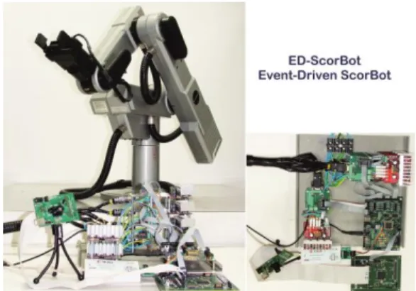
Besides the robot, the main polyvalent FPGA-based board used in this framework is the AER-Node [21]. Multiple units of this board can be connected in cascade (through AER buses) in order to increase the number of steps to perform the control, from the sensors to the actuators. Fig. 5 shows a photograph of the hardware components of the ED-Scorbot. In this figure, a DVS sensor is connected to an AER-Node board where BAF and OBT IPs are running on the FPGA. The output of the OBT is used as a reference for the 2D movement of the Scorbot. Spike-based SPID motor controllers are embedded in the same AER-Node board, although these motor controllers can be held into a different one, as it occurs with the SVITE algorithm. Its AER output bus is connected to the AER-Scorbot board, which decodes the AER bus into spikes to be sent to each motor. These spikes are properly expanded before they are sent to the motor. This expansion time constant represents the proportional constant of the SPID controller, which is also present and needed in the SVITE or any other pulse-frequency based motor controller.
AER-Node could also be devoted to implement high level cognition systems, such as vision or auditory integration / fusion systems, learning and classification through SNN [22] or ConvNets [8].
Several daughter boards can be connected to an AER-Node to improve its connectivity and functionality. The OKAER tool (used in [23]) is of particular interest; it allows sequencing and monitoring streams of events to and from the FPGA for debugging. It can also store in embedded DDR memory a long sequence of events to be sequenced repetitively. It also includes a merger for the sensory fusion algorithm implementations.
The Scorbot board collects spikes from the AER-Node in order to set the desired position of each motor. It collects information from motors (encoders and current spent by each motor) and makes a conversion of this information to spikes in order to send it back to the AER-Node. This board is connected to the power boards.
Each power driver board is composed of a bidirectional optocoupling layer, to isolate motor signals and logical signals from the AER-Scorbot board, and a Hall effect sensor. Information about encoders and current consumed by motors are sent to AER-Scorbot. Output expanded spikes from AER-Scorbot are sent to the Driver board (an H-Bridge) to supply a suitable voltage and current to drive the motor. A computer is connected to these boards in order to send parameters at running time, but it is also used for synthesizing our system for the FPGAs. This computer has access to the event-based IP library and it can be used locally or remotely through RemoteDesktop or VNC and a webcam to supervise the robot.
VI. CONCLUSIONS
This manuscript presents a test bed framework for neuromorphic systems implemented on FPGAs and it covers the whole process from sensors to actuators allowing the consecutive use of events (spikes) even for powering the motors. This framework is enriched by an IP library of
Fig. 5: Up. Block diagram of the VITE algorithm. Down. Block diagram of the SVITE generated from existing spikes processing blocks.
Hold &
Fire LPF Integrate and Generate TP PP DV PP Target Position (TP) Difference
Vector (DV) X Position (PP) Present
GO
GO BLOCK
event-based algorithms that will be continuously growing. Sensor’s filtering, integration, processing, learning and motor control are currently available.
Thanks to the use of the de facto standard AER for communicating events and wider parallel connectors, the framework boards can be connected to other existing platforms, such as SpiNNaker.
ACKNOWLEDGMENT
This research is supported by the Spanish grant (with support from the European Regional Development Fund) BIOSENSE (TEC2012-37868-C04-02) and the Andalusia Council Excellence grant MINERVA (P12-TIC-1300).
REFERENCES
[1] V. Chan, et al.,“AER EAR: A Matched FPGA Cochlea Pair With Address Event Representation Interface”. IEEE T. Circuits and Systems
54-I(1), pp. 48-59,2007
[2] R. Serrano-Gotarredona, et al., “On Real-Time AER 2-D Convolutions Hardware for Neuromorphic Spike-Based Cortical Processing”. IEEE
T. Neural Network 19(7), pp. 1196-1219,2008
[3] P. Hafliger, “Adaptive WTA with an Analog VLSI Neuromorphic Learning Chip”. IEEE T. Neural Networks18(2), pp. 551 – 572,2007 [4] G. Indiveri, et al.,“A VLSI Array of Low-Power Spiking Neurons and
Bistables Synapses with Spike-Timig Dependant Plasticity”. IEEE T.
Neural Networks 17(1), pp. 211 – 221, 2006
[5] M. Dominguez-Morales, et al.,“On the Designing of Spikes Band-Pass
Filters for FPGA”. Artificial Neural Networks and Machine Learning. ICANN 2011. LNCS 2011, 6792, pp. 389-396.
[6] Posch, C.; et al., "Retinomorphic Event-Based Vision Sensors: Bioinspired Cameras With Spiking Output," Proceedings of the IEEE , vol.102, no.10, pp.1470,1484, Oct. 2014.
[7] Koickal, T.J. et al. "Analog VLSI Circuit Implementation of an Adap-tive Neuromorphic Olfaction Chip," Circuits and Systems I: Regular Papers, IEEE Transactions on , vol.54, no.1, pp.60,73, Jan. 2007 [8] Zamarreno-Ramos, C. et al, "Multicasting Mesh AER: A Scalable
Assembly Approach for Reconfigurable Neuromorphic Structured AER Systems. Application to ConvNets," Biomedical Circuits and Systems, IEEE Transactions on , vol.7, no.1, pp.82,102, Feb. 2013
[9] D. Neil and S. C. Liu, "Minitaur, an Event-Driven FPGA-Based Spiking Network Accelerator," in IEEE Transactions on Very Large Scale Integration Systems, vol. 22, no. 12, pp. 2621-2628, Dec. 2014. [10] M. Sivilotti, Wiring Considerations in analog VLSI Systems with
Application to Field-Programmable Networks, Ph.D. Thesis, California Institute of Technology, Pasadena CA, 1991.
[11] Kwabena A. Boahen. “Communicating Neuronal Ensembles between Neuromorphic Chips”. Neuromorphic Systems. Kluwer, Boston 1998.
[12] jAER opensource project: http://sourceforge.net/p/jaer/wiki/Home/ [13] Jimenez-Fernandez A, et al. A Neuro-Inspired Spike-Based PID Motor
Controller for Multi-Motor Robots with Low Cost FPGAs. Sensors. 2012; 12(4):3831-3856.
[14] F. Perez-Pena, et al. “Neuro-inspired spike-based motion: from dynamic vision sensor to robot motor open-loop control through
spike-vite,” Sensors, vol. 13, no. 11, pp. 15 805–15 832, 2013.
[15] A. Linares-Barranco, et al, "A USB3.0 FPGA event-based filtering and tracking framework for dynamic vision sensors," ISCAS, Lisbon, 2015, pp. 2417-2420.
[16] R. Serrano-Gotarredona et al., "CAVIAR: A 45k Neuron, 5M Synapse, 12G Connects/s AER Hardware Sensory–Processing– Learning–
Actuating System for High-Speed Visual Object Recognition and Tracking," in IEEE Transactions on Neural Networks, vol. 20, no. 9, pp. 1417-1438, Sept. 2009.
[17] C. Farabet, et al. “Comparison Between Frame-Constrained Fix-Pixel-Value and Frame-Free Spiking-Dynamic-Pixel ConvNets for Visual
Processing”. Frontiers in Neuroscience. V6. N32. 2012.
[18] Lyon, R., A computational model of filtering, detection, and
compression in the cochlea. ICASSP ’82. IEEE International
Conference on Acoustics, Speech, and Signal Processing, 1982. [19] Jahn, A.F.; Santos-Sacchi, J. Physiology of the Ear. Singular, 2001.
[20] Lyon, R.F.; Mead, C. An Analog Electronic Cochlea. IEEE Trans. Acoustic Speech and Signal Processing. 1988, 36, 1119-1134. [21] T. Iakymchuk et al., "An AER handshake-less modular infrastructure
PCB with x8 2.5Gbps LVDS serial links," Circuits and Systems (ISCAS), 2014 IEEE International Symposium on, Melbourne VIC, 2014, pp. 1556-1559.
[22] F. Morgan, et al, "An evolvable NoC-based spiking neural network architecture," Signals and Systems Conference (ISSC 2009), IET Irish, Dublin, 2009, pp. 1-6.
[23] A. Rios-Navarro, et al. "Live demonstration: Real-time motor rotation frequency detection by spike-based visual and auditory AER sensory integration for FPGA," Circuits and Systems (ISCAS), 2015 IEEE International Symposium on, Lisbon, 2015, pp. 1907-1907.
[24] J.P. Dominguez-Morales. “Multilayer spiking neural network for audio samples classification using SpiNNaker”. Submitted to ICANN 2016. [25] A. Jimenez-Fernandez, et al. “A Binaural Neuromorphic Auditory
Sensor for FPGA: A Spike Signal Processing Approach”. Under review (minor changes) at IEEE-TNNLS.
[26] E. Cerezuela-Escudero, et al. "Musical notes classification with neuromorphic auditory system using FPGA and a convolutional spiking network," IJCNN-2015.
[27] L. Miró-Amarante, et al. “A spiking neural network for real-time
Spanish vowel phonemes recognition”. NeuroComputing. Under Review (minor changes)
[28] E. Zwicker, Subdivision the Audible Frequency range into Critical Bands., J. Acoust. Soc. Am. 33 (1961) 248. doi:10.1121/1.1908630. [29] F. Gómez-Rodríguez, et al, Two Hardware Implementations of the
Exhaustive Synthetic AER Generation Method, (2005) 534–540. [30] C. Kock, Biophysics of Computation, 1st ed., Oxford University Press,
Inc., New York, 1999.
[31] C. Eliasmith, Computation, Representation, and Dynamics in neurobiological systems, MIT Press, Cambridge, MA, USA, 2003. doi:10.1017/CBO9781107415324.004.
[32] M. Oster, S.-C. Liu, Spiking Inputs to a Winner-take-all Network, Adv. Neural Inf. Process. Syst. 18. (2006) 1051–1058.
Fig. 6: ED-Scorbot hardware components: Scorbot arm, Sensors (one DVS in the picture), AER-Node board, AER-Scorbot and power drivers.
Fig. 7: ED-Scorbot framework block diagram. Left are sensors (light red), AER-Node and AER-Scorbot PCBs (light green), which are parameterized through USB. The Scorbot motors are reached after a set of power drivers (purple). Many AER-Node boards can be connected in cascade.