Semantically Enhanced Mapping Algorithm for
Affinity-Constrained Service Function Chain
Requests
Niels Bouten
∗, Rashid Mijumbi
†, Joan Serrat
‡, Jeroen Famaey
§, Steven Latr´e
§, Filip De Turck
∗∗Department of Information Technology, Ghent University - iMinds, Technologiepark-Zwijnaarde 15, B-9052 Ghent, Belgium †Telecommunications Software and Systems Group, Waterford Institute of Technology, Ireland
‡Network Engineering Department, Universitat Polit`ecnica de Catalunya, 08034 Barcelona, Spain
§Department of Mathematics and Computer Science, University of Antwerp, Middelheimlaan 1, B-2020 Antwerp, Belgium
email: [email protected]
Abstract—Network Function Virtualization (NFV) and Soft-ware Defined Networking (SDN) have been proposed to increase the cost-efficiency, flexibility and innovation in network service provisioning. This is achieved by leveraging IT virtualization techniques and combining them with programmable networks. By doing so, NFV and SDN are able to decouple the network func-tionality from the physical devices on which they are deployed. Service Function Chains (SFCs) composed out of Virtual Network Functions (VNFs) can now be deployed on top of the virtualized infrastructure to create new value-added services. Current NFV approaches are limited to mapping the different VNFs to the physical substrate subject to resource capacity constraints. They do not provide the possibility to define location requirements with a certain granularity and constraints on the colocation of VNFs and virtual edges. Nevertheless, many scenarios can be envisioned in which a Service Provider (SP) would like to attach placement constraints for efficiency, resilience, legislative, privacy and economic reasons. Therefore, we propose a set of affinity and anti-affinity constraints, which can be used by SPs to define such placement restrictions. Furthermore, a semantic SFC validation framework is proposed that allows the Virtual Network Function Infrastructure Provider (VNFInP) to check the validity of a set of constraints and provide feedback to the SPs. This allows the VNFInP to filter out any non-valid SFC requests before sending them to the mapping algorithm, significantly reducing the mapping time.
I. INTRODUCTION
In traditional telecommunications networks, network func-tionality is strongly tied to the physical network device it runs on. To adapt or create network services, dedicated network appliances need to be deployed and interconnected in a strict order. Together with the ever increasing requirements for high quality and stability, this has led to long product cycles, limited service agility and substantial dependence on specialized hardware. The Network Function Virtualization (NFV) paradigm [1], [2] has been introduced to alleviate the aforementioned issues by leveraging IT virtualization technology to decouple the network functionality from the physical infrastructure. Furthermore, by taking advantage of Software Defined Networking (SDN), the network control and forwarding functions can be decoupled to allow an automated
network configuration to interconnect the various Virtual Net-work Functions (VNFs) in a flexible way. To fully exploit the benefits of both paradigms, the mapping of VNFs and the allocation of network resources interconnecting them, should be considered together. For example, when virtualizing the Customer Premises Equipment (CPE), not only the placement of the various functions (e.g., decoding function) needs to be optimized, also the allocation of network resources intercon-necting these functions should be considered (e.g., minimum throughput, maximum latency) to be able to deliver an end-to-end service.
The concepts of NFV and SDN have introduced new business opportunities for Virtual Network Function Infras-tructure Providers (VNFInPs), which act as brokers between Infrastructure Providers (InPs) and Service Providers (SPs) [3]. The VNFInPs lease the infrastructure provided by different InPs and deploy, orchestrate and interconnect VNFs to create end-to-end Service Function Chains (SFCs) [5]. Together with these new opportunities and stakeholders, a set of new interactions arises as well. For example, the SPs need a way to express their SFC requests and requirements to the VNFInP. In traditional network embedding approaches [6], only node and link restrictions can be specified. However, many scenarios can be envisioned where a SP might want to attach more detailed constraints concerning the placement and routing between Network Functions (NFs) as well as constraints on their colocation. For example, to increase efficiency, the SP may require the embedding of VNFs at a certain granularity (e.g., within the same datacenter or even on the same host). Other reasons for more detailed affinity and anti-affinity constraints could be resilience, economic, legislative and privacy issues. In this paper, a set of affinity and anti-affinity constraints is proposed that increases the control of SPs on the embedding of their SFC requests.
With this newfound ability to add custom constraints, the possibility arises that conflicting constraints are introduced by SPs in their requested SFCs. Therefore, the VNFInP requires a method to check the consistency of SFC requests and inform
1932-4537 (c) 2016 IEEE. Personal use is permitted, but republication/redistribution requires IEEE permission. See http://www.ieee.org/publications_standards/publications/rights/index.html for more information. This article has been accepted for publication in a future issue of this journal, but has not been fully edited. Content may change prior to final publication. Citation information: DOI 10.1109/TNSM.2017.2681025, IEEE
Transactions on Network and Service Management
the SP on potential conflicts. For example, if the SP states that two VNFs of certain types need to be embedded on the same host, but also requires that any instances of functions with those VNF types are required to be embedded in distinct datacenters, a conflict arises. Since SFC requests can contain many VNFs, virtual edges and constraints, detecting conflicts within these requests is not a straightforward task, neither for human operators, nor for computer systems. Since conflicts can arise between sets of constraints, pairwise detection will not suffice. Therefore, this chapter proposes to take advantage of semantic modelling to define an ontology and rule set, which can be enriched with individuals based on the specific SFC request. Using a semantic reasoner, the consistency can be determined and subsequently the validity of the SFC request can be assessed. Furthermore, the proposed framework can also be used by SPs to validate the SFC embeddings made by the VNFInP with respect to the imposed affinity requirements. Existing VNF and Virtual Network (VN) embedding ap-proaches focus on the resource constraints posed by the SFC requests or take into account other types of constraints, such as forwarding latency, processor and resource sharing, VNF precedence constraints, etc. These approaches do not provide the opportunity to add placement constraints to both VNF placement and virtual edge allocation. Therefore, this paper focuses on the the affinity-constrained SFC placement problem. First, the resource and flow conservation constraints are modeled for the concurrent mapping of SFCs sets. Second, the affinity and anti-affinity constraints are added to the model. Finally, to allow scalable SFC mapping, a heuristic procedure is proposed. This heuristic approach takes advantage of additional knowledge of the SFC set to sort the individual SFCs in a way that optimizes the objective. Both the optimal and heuristic approaches are evaluated considering different metrics and use cases, such as the number of VNFs in an SFC, the size of the physical infrastructure, the number of SFCs in a set and the impact of applying semantic filtering to the SFC request set prior to embedding.
The contributions of this paper are fourfold. First, a set of affinity and anti-affinity constraints that can be attached to an SFC request by the SP are defined. Second, we propose and evaluate a semantic conflict detection mechanism that can be employed by the VNFInP to check the validity of SFC requests. In this way, SFCs containing inconsistent constraints can be filtered out by the VNFInP before the embedding step. Third, we propose a mathematical formulation of the affinity-constrained SFC embedding problem and a set of algorithms to solve them. Finally, a heuristic approach to tackle the computationally expensive task of embedding SFC sets is proposed and evaluated.
II. RELATEDWORK
NFV has been proposed as a paradigm that allows more flexible service deployment by leveraging IT virtualization technology in combination with programmable networks [7], [8]. A recent survey on NFV by co-authors of this paper, identifies the decoupling of NFs from hardware, flexible NF
deployment and dynamic scaling as the main differences between network service provisioning in NFV compared to current practice [9].
Affinity and anti-affinity restrictions have previously been studied in the context of grid and cloud computing. Many ar-gued that the lack of influence on the placement of workflow or service components is a hindrance for the adoption of the tech-nology [10], [11]. Even though performance and economical benefits of cloud computing are clear, potential users hesitate to deploy the technology because legal, privacy, efficiency and resilience aspects are completely out of their control. Also, recent media coverage shows an increased concern by end-users, companies and governments about their data privacy, raising the need for SPs to take into account these issues when deploying and offering their services1,2. These concerns also arise for NFV when deploying VNFs at certain locations and transferring data between them over virtual paths. Therefore, we argue that also in NFV, mechanisms should be designed to allow SPs to add constraints concerning locality and affinity, both to VNFs as well as the interconnecting paths.
The solutions proposed in the affinity and anti-affinity context for cloud computing mostly relate to two aspects: developing models to describe affinity rules and developing service placement algorithms that can work under the con-straints of these rules.Konstanteli et al.present a set of affinity rules for cloud computing applications which are added to a Mixed-Integer Non-Linear Programming (MINLP) [12]. The authors define constraints that require allocating components and services in the same subnet or physical node, or prevent services from being federated. Larsson et al. and Espling et al. propose a model for defining Virtual Machine (VM) placement in cloud computing supporting a set of affinity and anti-affinity constraints [13], [14]. We extend this approach by defining affinity and anti-affinity restrictions for SFCs. To this end we add support for specification of constraints on the path between network functions and furthermore, a more expressive syntax that allows constraints to apply to specific VNFs, VNF types, locations and location types. A semantic framework is proposed which allows to check the validity of these constraints.
One of the benefits of NFV is that it supports automated deployment and orchestration of services. To achieve this, a number of descriptions are needed for everything that was configured manually in the past, including VNFs and network requirements [3]. Also, Service Level Agreement (SLA)-related parameters such as affinity and anti-affinity rules should be transformed into machine-readable description formats [15]. Huawei mentions the generation of affinity and anti-affinity policies as a mechanism for fault prevention [16]. In the definition of Service Quality Metricsby ETSI, special
1No Safe Harbor: How NSA Spying Undermined U.S. Tech and
Eu-ropeans’ Privacy – https://www.eff.org/nl/deeplinks/2015/10/europes-court-justice-nsa-surveilance
2Facebook case may force European firms to change data storage
practices – http://www.theguardian.com/us-news/2015/sep/23/us-intelligence-services-surveillance-privacy
attention is brought to the enforcement of NFV customer anti-affinity rules which can improve the availability mech-anisms [17]. The automatically generated affinity rules for VNFs in combination with user-specific affinity requirements could lead to conflicting constraints. In this paper, a machine-readable format for affinity and anti-affinity constraints is proposed. Furthermore, we establish an automated way to detect conflicting constraints based on ontologies. The pro-posed conflict detection is applicable to both user-generated as well as automatically generated affinity constraint sets. Furthermore, the proposed framework can also be used to validate SFC embeddings with respect to the imposed affinity requirements.
To attain the gains promised by NFV, the VNFs and interconnecting virtual links should be efficiently mapped onto the physical substrate. To achieve this, several placement algorithms have been proposed in the related fields of Virtual Network Embedding (VNE) [6] and Virtual Data Center Net-work Embedding (VDCNE) [18], [19], as well as for NFV [9]. In the field of NFV, Mehraghdam et al. apply Mixed Integer Quadratically Constrained Programming (MIQCP) to solve the placement problem and conclude that to obtain efficient use of resources, the placement of functions should be different according to the desired objective [20]. Beck et al. propose a coordinated allocation heuristic based on the backtracking concept in which they take into account that the structure of SFCs can be flexible [21]. This allows to reorder some of the VNFs in coordination with the allocation of the SFC. Also Mehraghdam et al. take into account such flexible structures [22]. However, they propose a two-step approach without coordination between the SFC composition and embedding. Moens et al. propose an Integer Linear Programming (ILP) based solution in which hybrid scenarios are considered where part of the functions are provided by dedicated physical hardware and part of them by virtualized instances [23]. Luizellie et al. formalize the NF placement and chaining problem and propose an ILP model to solve it [24]. Xia et al. propose a Binary Integer Programming (BIP) model for optimal VNF placement subject to minimizing the expensive optical/electronic/optical conversions for NFV chaining in packet/optical data centers [25]. Sahhaf et al.
propose an algorithm for mapping SFCs to the network infras-tructure while taking into account decompositions of NFs [26].
Yoshida et al.propose a multi-objective resource scheduling al-gorithm simultaneously optimizing possibly conflicting objec-tives with multifaceted constraints [27].Vaishnavi et al.tackle the problem of inter-domain virtual network provisioning by abstracting the resources of a domain to appear as a single node [28]. In previous work, we formulated the online virtual function mapping and scheduling problem and proposed a set of algorithms for solving it [29]. Other research focuses on specific NFV uses cases such as virtualizing the CPE, Evolved Packet Core (EPC) or Deep Packet Inspection (DPI) [30], [31], [32], [33]. For an extended overview of resource allocation in NFV, we refer to a survey byHerrera et al.[34]. None of the aforementioned approaches offers support for attaching affinity
or anti-affinity constraints to the SFCs nor do they take into account such constraints when evaluating the embeddings.
This paper is an extension of previous work [35] in which the affinity and anti-affinity constraints were first proposed. The previous paper proposed a first version of the semantic framework for affinity-constrained SFCs validation. In the current paper, the aforementioned framework was further fine-tuned and extended with embedding algorithms for affinity-constrained SFCs. Furthermore, using the mathematical model proposed in this paper, the semantic filtering is validated. Also the impact of applying semantic filtering prior to the embedding is evaluated in this paper.
III. AFFINITY ANDANTI-AFFINITYCONSTRAINTS
Currently, in an NFV context, SPs have limited control over the mapping of VNFs to physical hosts or SFC edges to phys-ical paths. Nevertheless, many situations can be envisioned where an SP might want to attach constraints to the placement of certain functions or on the routing of traffic, such as:
• Efficiency: VNFs that exchange a lot of data may want to be positioned close to one another (e.g., within the same datacenter, or even on the same physical host). • Resilience: The SP might want to spread instances of
the same VNF across multiple datacenters in order to improve resilience in case a failure occurs in one of the datacenters.
• Legislation:The SP might want to avoid hosting VNFs in certain countries due to legislative restrictions on the location of the data that is processed or transferred. • Privacy:SPs or their customers might not want the traffic
to pass through certain domains due to privacy concerns. • Economic:SPs might have economic reasons (e.g., peer-ing agreements) to place their functions in or route their traffic through certain domains.
However, currently there is no way to specify or model such requirements in an SFC template. In this section, the set of affinity and anti-affinity constraints for VNFs and their interconnecting paths are discussed. The affinity constraints apply to a set of physical locationsP, a set of VNF instances
V and a set of edges E interconnecting them. There are different location granularitiesg ∈ Gthat can be considered (e.g., countries, network domains, datacenters), leading to a hierarchical structure of locations. Two hosts in a single data-center represent different locations at the granularity of hosts, but have the same location at the granularity of datacenters.
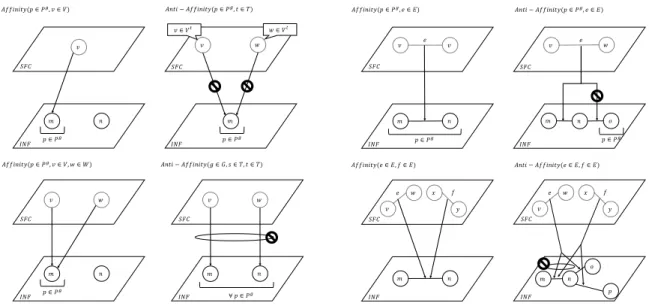
Pg ⊆ P is the set of locations at a certain granularity g. Furthermore, each VNF instance has an associated VNF type (e.g., firewall, DPI), forming subsets Vt⊆V of VNFs with typet∈T. Finally, each virtual edgee= (a, b)∈Econnects two VNFsa∈V andb∈V and maps to a single (or path of) physical network links. We propose and define four groups of constraints which model location and colocation constraints, both for VNFs and virtual edges, each consisting of pairs of affinity and anti-affinity constraints. Figure 1 shows a graphical illustration of a subset of the constraints defined below:
1932-4537 (c) 2016 IEEE. Personal use is permitted, but republication/redistribution requires IEEE permission. See http://www.ieee.org/publications_standards/publications/rights/index.html for more information. This article has been accepted for publication in a future issue of this journal, but has not been fully edited. Content may change prior to final publication. Citation information: DOI 10.1109/TNSM.2017.2681025, IEEE
Transactions on Network and Service Management
𝑣 𝑆𝐹𝐶 𝐼𝑁𝐹 𝑚 𝑛 𝑝 ∈ 𝑃, 𝐴𝑓𝑓𝑖𝑛𝑖𝑡𝑦(𝑝 ∈ 𝑃,, 𝑣 ∈ 𝑉) 𝐴𝑛𝑡𝑖 − 𝐴𝑓𝑓𝑖𝑛𝑖𝑡𝑦(𝑝 ∈ 𝑃,, 𝑡 ∈ 𝑇) 𝑣 𝑚 𝑝 ∈ 𝑃, 𝑣 ∈ 𝑉8 𝑤 𝑤 ∈ 𝑉8 𝑣 𝑆𝐹𝐶 𝐼𝑁𝐹 𝑚 𝑛 𝑝 ∈ 𝑃, 𝐴𝑓𝑓𝑖𝑛𝑖𝑡𝑦(𝑝 ∈ 𝑃,, 𝑣 ∈ 𝑉, 𝑤 ∈ 𝑊) 𝑤 𝑆𝐹𝐶 𝐼𝑁𝐹 𝑣 𝑆𝐹𝐶 𝐼𝑁𝐹 𝑚 𝑛 𝐴𝑛𝑡𝑖 − 𝐴𝑓𝑓𝑖𝑛𝑖𝑡𝑦(𝑔 ∈ 𝐺, 𝑠 ∈ 𝑇, 𝑡 ∈ 𝑇) 𝑤 ∀ 𝑝 ∈ 𝑃, 𝑣 𝑆𝐹𝐶 𝐼𝑁𝐹 𝑚 𝑛 𝑝 ∈ 𝑃, 𝐴𝑓𝑓𝑖𝑛𝑖𝑡𝑦(𝑝 ∈ 𝑃,, 𝑒 ∈ 𝐸) 𝐴𝑛𝑡𝑖 − 𝐴𝑓𝑓𝑖𝑛𝑖𝑡𝑦(𝑝 ∈ 𝑃,, 𝑒 ∈ 𝐸) 𝑣 𝑝 ∈ 𝑃, 𝑤 𝑣 𝑆𝐹𝐶 𝐼𝑁𝐹 𝑚 𝑛 𝐴𝑓𝑓𝑖𝑛𝑖𝑡𝑦(𝑒 ∈ 𝐸, 𝑓 ∈ 𝐸) 𝑤 𝑆𝐹𝐶 𝐼𝑁𝐹 𝐴𝑛𝑡𝑖 − 𝐴𝑓𝑓𝑖𝑛𝑖𝑡𝑦(𝑒 ∈ 𝐸, 𝑓 ∈ 𝐸) 𝑣 𝑒 𝑚 𝑛 𝑜 𝑒 𝑥 𝑦 𝑒 𝑓 𝑣 𝑆𝐹𝐶 𝐼𝑁𝐹 𝑚 𝑛 𝑤 𝑥 𝑦 𝑒 𝑓 𝑜 𝑝
Fig. 1: Graphical illustration of the various affinity and anti-affinity constraints ∗ Affinity(p ∈ Pg, v ∈ V or t ∈ T): a specific
instancevor all instancesv∈Vtof typet∈T must be located at a specific location p with granularity
g.
∗ Anti-Affinity(p∈ Pg, v ∈ V or t ∈ T): a specific instance v or all instances v ∈ Vt of type t ∈ T must not be located at a specific location p with granularityg.
• VNF Colocation Constraints:
∗ Affinity(p ∈ Pg or g ∈ G, v ∈ V or s ∈ T, w ∈
V ort ∈ T): a specific instance v or all instances
v∈Vsof type s∈T must be placed together with a specific instancewor all instancesw∈Vtof type
t ∈T at a specific location p∈Pg or at the same location at a specific granularityg∈G.
∗ Anti-Affinity(p ∈ Pg org ∈ G, v ∈ V ors ∈
T, w ∈ V ort ∈ T): a specific instance v or any instances v∈Vs of types∈T must not be placed together with a specific instance wor any instances
w∈Vt of typet∈T at a specific locationp∈Pg or at the same location at a specific granularity
g∈G.
• Virtual Edge Location Constraints:
∗ Affinity(p∈Pg, e∈E): a virtual edgee∈E must be fully embedded at a specific locationp∈Pgwith a granularity g ∈ G. It does not suffice to model this as location constraints on the endpoints, since physical nodes along the virtual path can still be located in other locations q∈Pg\ {p}.
∗ Anti-Affinity(p ∈ Pg, e ∈ E): the physical links comprising the virtual edge e ∈ E must not pass through a specific locationp∈Pgwith a granularity
g∈G.
• Virtual Edge Colocation Constraints:
∗ Affinity(e ∈ E, f ∈ E): two virtual edges e ∈ E
f1:Firewall c1:Cache c2:Cache d:DPI f2:Firewall s:StreamingServer t:Transcoding e1 e2 e4 e5 e7 e6 e8 c:Cache e3 Fig. 2: An example SFC.
and f ∈ E must overlap (i.e. all physical links comprising the edge e must be the same as those comprising edgef).
∗ Anti-Affinity(e∈E, f ∈E): two virtual edgese∈
E and f ∈ E must not overlap (i.e. none of the physical links comprising the virtual edges shall be part of both e and f). Modelling this as an anti-affinity constraint for the VNFs of the endpoints of
e and f does not achieve this, since the physical paths can still have overlapping links even though the endpoints are mapped to distinct physical nodes. To further clarify the presented constraint formulations, an example of an SFC request with both affinity and anti-affinity constraints is given here. Given a set of location types {Autonomous System (AS), Datacenter (DC), Host} and a set of network function types{Firewall, DPI, Cache, Transcoding, Streaming Server}. An example SFC is depicted in Figure 2, where a Streaming Server is connected via a DPI function (e.g., for tagging data packets) to a content cache. The DPI functions may either directly forward requests to the streaming server or may send them via theTranscoder for transcoding and packaging (e.g., for delivery to mobile devices). The transcoding is preceded by aCache in the chain to store the transcoded content. The end-users are connected via a firewall to the service. Suppose a SP wants to offer a Video on Demand (VoD) service in Belgium where two infrastructure providers are active: Telenet (AS6848) and Proximus (AS6774).
Further-more, the SP wants to deploy part of the service in an Amazon DC identified by DC AWS. Let us consider the following set of affinity and anti-affinity constraints:
• Affinity(AS6848, c1) • Affinity(AS6774, c2)
• Affinity(DC, Transcoder, Streaming Server) • Affinity(DC AWS, e2)
• Affinity(Host, t, c) • Anti-Affinity(e1, e3)
Specifically, the first two constraints state that the Caches c1 and c2 need to be located in the Telenet and Proximus AS respectively (e.g., because they should be close to the end user and limit uplink traffic through other networks). The third constraint states that, for efficiency reasons and for reducing the network traffic, all Transcoder functions should be colocated with the Streaming Server functions. The next constraint states that the virtual edge e2 should be fully embedded within the scope of theDCidentified byDC AWS. The fifth constraint assures that the Transcoder t and the
Cache c should be located at the sameHost. Finally, the last constraints dictates that none of the physical links that are used for the embedding of the virtual edges e1ande3are allowed to overlap.
IV. SEMANTICSFC REQUESTCHECKER
Since SPs are now free to specify their custom constraints during the SFC request, it is possible that conflicting con-straints are introduced. Extending the example from the pre-vious section and adding the constraints Affinity(Host, c1, f1)
(i.e. specifying thatc1andf1should be colocated in the same Host) and AntiAffinity(DC, Cache, Firewall) (i.e. specifying that a VNF of type Cache cannot be colocated with a VNF of type Firewall in the scope of a DC) leads to a conflicting constraint set. Also more complex conflicts can appear when multiple constraints are involved in the conflicting set that can only be detected as a conflict when considering the full set. For example, returning to the base example from the previous section and adding the constraints Affinity(DC, DPI, Cache) and Anti-Affinity(DC AWS, d) would lead to a conflict set {Affinity(Host, t, c), Anti-Affinity(DC AWS, d), Affinity(DC AWS, e2), Affinity(DC, DPI, Cache)}. Sincedand
c should be colocated in the same DC due to the VNF type affinity constraint andtandcare colocated at theHostlevel,d
andtshould be colocated at theDClevel as well. Furthermore, sincee2should be fully embedded inDC AWS,tshould also be located inDC AWS. This means thatdshould be located in
DC AWS as well. However, this inferred knowledge conflicts with the defined constraint Anti-Affinity(DC AWS, d).
When the VNFInP tries to deploy the requested SFC, none of the resulting embedding configurations will lead to a feasible realisation of the SFC request. The VNFInP should however be able to differentiate between a non-acceptance of the SFC request caused by a shortage of appropriate resources and conflicting request constraints, in order to inform the SP on the reason why the SFC deployment failed. The previous example shows the need for the VNFInP to check the validity
of an SFC request upon reception in order to exclude any conflicting constraints when trying to provision the requested SFC.
In the proposed architecture, theSFC Embedding Algorithm
(which will be discussed in the next section) is responsible for assigning resources to the SFC requests. Concretely, it decides on which VNFs should be deployed on which hosts and how many resources should be assigned to them. The
Cloud Managerperforms the management of deployed VNFs and server resources. Moreover, the algorithm selects the for-warding paths interconnecting the VNFs and assigns network resources to them through theSDN Controller. Before the SFC request is forwarded to theSFC Embedding Algorithmit needs to be checked by the SFC Request Checker to confirm the validity.
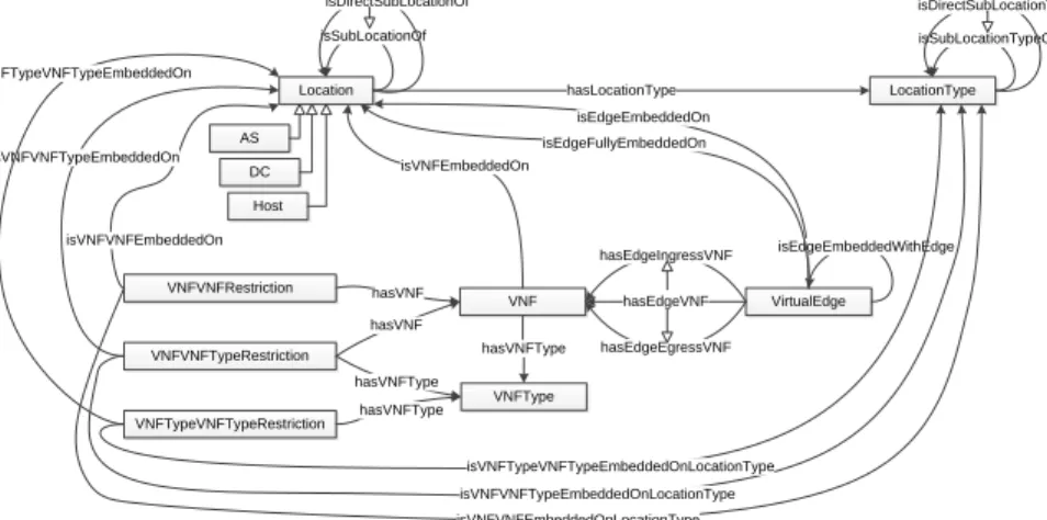
In previous work we proposed to exploit ontology repre-sentations for the purpose of modeling the physical substrate, the SFC requests and defining a set of rules that can be used to infer additional information [35]. Figure 3 represents the proposed semantic model. The SFC requests are modeled as a set of VNFs with a certain VNFType and VirtualEdges
containing an ingress and egressVNF. The physical resources are modeled at the granularity level of Hosts,DCs andASs. Each of theseLocations has a certainLocationType (i.e., AS, DC or Host). The hierarchical relations between these Loca-tions and LocationTypes are modeled by isSubLocationOf
and isSubLocationTypeOf respectively. To model affinity
(respectively anti-affinity) constraints for single VNFs and edges, positive (respectively negative) object property asser-tions of the typeisVNFEmbeddedOn,isEdgeEmbeddedOn
and isEdgeFullyEmbeddedOn are attached to VNFs and
VirtualEdges.
To be able to model more complex affinity and anti-affinity relationships between two VNFs, two VNFTypes
or between a VNF and VNFType, the additional concepts VNFVNFRestriction, VNFVNFTypeRestriction
and VNFTypeVNFTypeRestriction were added to the ontology. By adding the respective positive (respectively
negative) property isVNFVNFEmbeddedOn or
isVNFVNFEmbeddedOnType, one is able to model
affinity (respectively anti-affinity) restrictions for more complex constraints on the Location or LocationType. By using the isEdgeEmbeddedWithEdge relationship, affinity and anti-affinity constraints between edges can be modeled.
To infer new information out of existing knowledge, a set of rules is defined. For example, Rule (1) stipulates that if a certain VNF x is embedded on aLocation y and if y is a sublocation of z, thisVNF is also embedded on Location z. When aVNFType y is embedded on a Location z, eachVNF x of that VNFType y needs to be embedded at theLocation z (Rule (2)). If a VirtualEdge z contains a VNF x embedded atLocation a, thisVNF zis embedded at Location aas well (Rule (3)). For a full description of the rules, we refer to previous work [35] which focuses on the semantic validation of SFC requests.
Location LocationType AS DC Host isSubLocationOf hasLocationType VNF VirtualEdge isVNFEmbeddedOn isEdgeEmbeddedOn VNFType hasVNFType hasEdgeVNF hasEdgeIngressVNF hasEdgeEgressVNF isEdgeEmbeddedWithEdge VNFVNFRestriction VNFVNFTypeRestriction VNFTypeVNFTypeRestriction hasVNF hasVNFType hasVNFType isVNFVNFEmbeddedOn isVNFVNFTypeEmbeddedOn isVNFTypeVNFTypeEmbeddedOn isSubLocationTypeOf isVNFVNFTypeEmbeddedOnLocationType isVNFTypeVNFTypeEmbeddedOnLocationType isVNFVNFEmbeddedOnLocationType isDirectSubLocationOf isDirectSubLocationTypeOf hasVNF isEdgeFullyEmbeddedOn
Fig. 3: Graphical representation of ontology.
isV N F EmbeddedOn(x, y)∧isSubLocOf(y, z)
→isV N F EmbeddedOn(x, z) (1)
hasV N F T ype(x, y)∧isV N F T ypeEmbeddedOn(y, z)
→isV N F EmbeddedOn(x, z) (2)
hasEdgeV N F(z, x)∧isV N F EmbeddedOn(x, a)
→isEdgeEmbeddedOn(z, a) (3)
When a new SFC request arrives at the VNFInP, this request is parsed and the set of VNFs and edges are added as individuals to the Web Ontology Language (OWL) ontology. Next, the set of affinity and anti-affinity con-straints are also added by either creating new individ-uals (i.e. VNFVNFRestriction), adding property asser-tions (i.e. isVNFEmbeddedOn) or both. For example, the affinity restriction Affinity(AS6848, c1) concerning VNF c1
and AS AS6848, is modeled as a positive property
asser-tion isVNFEmbeddedOn(c1,AS6848). On the other hand,
the negative restriction Anti-Affinity(e1, e3) concerning Vir-tualEdge e1 and VirtualEdge e3, is modeled as a negative property assertion isEdgeEmbeddedWithEdge(e1,e3).
V. MODEL
In this section the affinity-constrained SFC placement prob-lem is described. First, the notations for the inputs and vari-ables used throughout the chapter are presented. Second, the general constraints involved in SFC placement are introduced. Third, the constraints related to affinity and anti-affinity based placement restrictions are explained. Finally, the placement objectives are introduced. Figure 4 shows a graphical repre-sentation of the variables and their relationships.
A. NFV Infrastructure model
The topology of an NFV infrastructure can be described as a weighted directed graphIN F ={N, L}, whereN is the set of substrate nodes in the infrastructure and Lthe set of links interconnecting them. Each substrate node n∈N represents a location where a network function could be deployed. Each
𝑎 𝑏 𝑣 𝑤 𝑢 𝑆𝐹𝐶: 𝑟 ∈ 𝑅 𝑢, 𝑣 ∈ 𝐸0 𝑠 ∈ 𝑆0 𝑐 𝑉04= 𝑎, 𝑏, 𝑐 𝐸04= { 𝑎, 𝑏 , (𝑏, 𝑐)} 𝑤 ∈ 𝑉0: 𝑅 𝐷4 𝐷(<,=) 𝑆0= 𝑠 𝑉0= 𝑢, 𝑎, 𝑏, 𝑐, 𝑣, 𝑤 𝑉0:= 𝑢, 𝑤, 𝑐 𝐸0= 𝑢, 𝑎 , 𝑎, 𝑏 , 𝑏, 𝑐 , 𝑢, 𝑣 , 𝑣, 𝑤 𝐵(?,<) 𝑚 𝑛 𝑘 l o 𝐼𝑁𝐹 𝑜 ∈ 𝑁 𝐷(F,G) 𝐵(G,H) 𝑚, 𝑛 ∈ 𝐿 𝑝 𝑞 𝑁 = 𝑘, 𝑙, 𝑚, 𝑛, 𝑜 𝐿 = { 𝑘, 𝑙 , 𝑘, 𝑚 , 𝑚, 𝑛 , 𝑛, 𝑜 , 𝑜, 𝑙 , 𝑙, 𝑘 , 𝑚, 𝑘 , 𝑛, 𝑚 , 𝑜, 𝑛 , (𝑙, 𝑜)} ℎN ℎO 𝐷𝐶 ℎ𝑜𝑠𝑡 𝑔 ∈ 𝐺 𝐶G, 𝑀G, 𝑄G ℎU ℎV ℎW 𝑥H< 𝑡, 𝐶<, 𝑀<, 𝐷<, 𝑄< 𝑦(H,G)(?,<) 𝑧0 𝑃\]= 𝑝, 𝑞 𝑁^\]= 𝑘, 𝑚
Fig. 4: Graphical representation of the SFC placement model.
substrate node n is characterized by its available processing capacityCn, available memory capacity Mn and its location
p ∈ P. This geographic location represents a hierarchical structure where each level of this structure represents a certain geographic granularity (e.g., host, rack, datacenter, network domain, etc.). The subset of geographic locations Pg ⊆ P represents the set of locations at a particular granularityg∈G
(e.g., PDC represents the set of all datacenter locations). Similarly, Npg represents the set of all substrate nodes at a geographic location p ∈ Pg at a certain granularity g (e.g.,
NpDC represents the set of all substrate nodes located at a datacenter p). It is possible that a certain network node n is not involved directly in mapping VNFs for an SFC but is along the path between VNFs and thus participates in forwarding the traffic for the SFC. Therefore we need to take into account the packet processing capacity of such a node:Qnwhen deploying
SFCs on the substrate network.
Each link (m, n) ∈ L represents a unidirectional link between two network nodes m, n ∈ N. Bidirectional links are represented as a pair of unidirectional links (i.e.
(m, n),(n, m)). This allows us to model a variety of network links with different up/download characteristics. Each link is characterized by an available bandwidth capacity B(m,n)and
latency D(m,n). Similar to network nodes, also the links are
characterized by a geographic location which is the set of locations of their endpoints{Pm, Pn}.
B. SFC model
Similarly to the VNF infrastructure model, an SFC request
r∈Rcan be described as a weighted directed graphSF Cr=
{Vr, Er}, whereVris the set of VNFs andErthe set of edges interconnecting them. An SFC typically has two or multiple endpoint VNFs which terminate the service chain. These are modeled as endpoint-VNFs Ve
r ⊆ Vr. Tr represents the set of VNF types (e.g., firewall, gateway, router). Each VNFv∈
Vr has an associated VNF typet ∈ Tr. Vrt forms the set of VNFs in the SFC that have a type t associated with them. Each VNF v requires a certain processing capacityCv and a specific memory capacity Mv. Furthermore, each VNF v has an associated processing delayDv.
Each edge (u, v) ∈ Er represents a unidirectional virtual edge between two VNFs u, v ∈ Vr. These are modeled as unidirectional connections since SFCs can have different capacity requirements for up-and downstream respectively (e.g., a video streaming SFC will have higher downstream requirements). An SFC edge can be composed of one or more substrate links or could be an internal link when bothuandv
are mapped onto the same substrate noden. Link aggregation, where a virtual edge is composed out of multiple distinct underlying paths, is not considered here. Each edge has a required capacity B(u,v) between the VNFs, this capacity is
also used to account for the packet processing requirements of the forwarding nodes (i.e. Qn). A section or path s∈Sr is a tuple composed of a set of ordered VNFs Vs
r and the ordered set of consecutive virtual edges interconnecting these VNFsEs
r. An SFC requestrcan associate a maximum allowed latencyDsfor the end-to-end flow processing of such sections.
Ar denotes the affinity and anti-affinity constraints that are defined in the SFC request r. Aar and Aaar denote the set of affinity constraint and anti-affinity constraints respectively.
C. Assignment variables
For every SFC request r ∈ R, a set of node and link mapping variables is defined. The binary variable zr defines whether the SFC r ∈ R is mapped or not as defined in Expression (4). The binary variable xis used in the mapping of the VNFs to network nodes and is defined in Expression (5), where xv
n →N·Vr. Similarly, the binary variable y is used as defined in Expression (6), where y((m,nu,v))→L·Er.
zr = 1, ifr∈Ris mapped. 0, otherwise. (4) ∀r∈R:xvn = 1, ifv∈Vr is mapped ton∈N . 0, otherwise. (5) ∀r∈R:y((u,vm,n)) = 1, if(u, v)∈Er is mapped to(m, n)∈L. 0, otherwise. (6) D. General constraints
In order to assure a correct mapping of the requested SFC, a set of constraints can be defined. Equations (7) and (8) prevent that VNFs and virtual edges respectively are mapped when the corresponding SFC to which they belong is not mapped. Equation (9) ensures that if an SFC requestris mapped (zr=
1), each VNF is assigned and that it is assigned to exactly one node. On the other hand, if the SFC requestr is not mapped (zr = 0), none of the VNFs should be mapped. Equations (10) and (11) respectively assure that the available CPU and memory capacity of each individual node is not exceeded by the capacity requirements of all VNFs v ∈ V in the request setR(V =S r∈RVr). ∀r∈R:∀v∈Vr:∀n∈N:xvn≤zr (7) ∀r∈R:∀(u, v)∈Er:∀(m, n)∈L:y (u,v) (m,n)≤zr (8) ∀r∈R:∀v∈Vr: X n∈N xvn=zr (9) ∀n∈N:X v∈V (xvn·Cv)≤Cn (10) ∀n∈N:X v∈V (xvn·Mv)≤Mn (11) ∀(u, v)∈E, m∈N : X n∈N y((m,nu,v))−X n∈N y((u,vn,m))=xum−xvm (12) ∀(m, n)∈L: X (u,v)∈E y((u,vm,n))·B(u,v) ≤B(m,n) (13) ∀n∈N: X u∈V (xun·Qu) + X (u,v)∈E 2·xun·xvn·B(u,v) + X (u,v)∈E X (m,n)∈L (n,o)∈L
y((u,vm,n))+y((n,ou,v))
·B(u,v) ≤Qn (14) ∀r∈R:∀s∈Sr : X u∈Vrs X n∈N (xun·Du)+ X (u,v)∈Es r X (m,n)∈L y((m,nu,v))·D(m,n) ≤Ds (15)
The multi-commodity flow conservation is assured by Equa-tion (12). This ensures that there exist virtual paths between the requested VNFs. Modeling that no capacity is required for a certain virtual edge (u, v), while a virtual edge (v, u)
1932-4537 (c) 2016 IEEE. Personal use is permitted, but republication/redistribution requires IEEE permission. See http://www.ieee.org/publications_standards/publications/rights/index.html for more information. This article has been accepted for publication in a future issue of this journal, but has not been fully edited. Content may change prior to final publication. Citation information: DOI 10.1109/TNSM.2017.2681025, IEEE
Transactions on Network and Service Management
by setting B(u,v) = 0 and B(v,u) > 0 respectively. Using
the constraint defined in Equation (13), we ensure that each substrate link has enough capacity to serve all virtual paths
(u, v)∈R mapped on it for a request setR(E=S
r∈REr). Equation (14) guarantees that the required processing capacity is available for each of the substrate nodes. The first term sums up the required capacityBuby each VNFu∈V. The second term assures that if a virtual edge is mapped internally within a single substrate node, the required processing capacity for this edge is added. The last term sums up the processing capacity of each ingress and egress links of a substrate node. Finally, Equation (15) ensures that the end-to-end latency incurred by the substrate links comprising the virtual paths s ∈ Sr and the processing delays at the VNFs adhere to the maximum allowed latency Ds specified by the SFC requestr∈R.
E. Affinity and Anti-Affinity constraints
To take into account the required geographic and colocation requirements for a specific VNF requestr, these are modeled as constraints for the optimization problem. Equation (16) stipulates that all VNFs of a certain typetneed to be located at a location pwith granularityg, while Equation (17) prevents the embedding of any VNF of type t at this location p. To model the affinity of certain VNF types s and t at a any location with granularity g, Equation (18) guarantees that every VNF v of types is embedded with all VNFs of typet
(=|Vt|) at a single locationpwith granularityg. Equation (19) prevents a VNF of typesto be embedded with a VNF of type
tat the same locationpwith granularityg. Similar constraints were added for the other affinity and anti-affinity constraints involving VNFs and VNF types defined in Section III.
Next to VNF affinity constraints, link affinity constraints are also modeled. Equation (20) assures that every substrate link
(m, n)on which a virtual edge(v, w)is mapped, is located at a location p∈ Pg. Furthermore, since edges can be mapped internally (i.e. both VNFsv andware mapped onto the same substrate node), Equation (21) ensures that also the VNFs v
and w are mapped onto a host at that location n ∈ Ng p. To prevent the mapping virtual edges (u, v)at a certain location
p ∈ Pg, Equation (22) ensures that none of the substrate links (m, n) for which one of the endpoints is located at that location (m∨n∈Ng
p) is used. Similarly, Equation (23 prevents the internal embedding of the virtual edge (v, w)at that location.
Equation (25) stipulates that two virtual edges need to be mapped onto the same virtual path. Equation (24) ensures that the corresponding endpoints of the virtual edge are mapped onto the same host. This constraint takes care of the cases where the virtual edges are mapped internally. Equation (26) prevents two virtual edge mappings of sharing a link. Further-more, none of the endpoints of these respective virtual edges should be colocated at the same host (Equation (27))
Affinity(p∈Pg, t∈Tr) : ∀v∈Vrt: X n∈Npg xvn=zr (16) Anti-Affinity(p∈Pg, t∈Tr) : ∀v∈Vrt: X n∈Npg xvn= 0 (17) Affinity(g∈G, s∈Tr, t∈Tr) : ∀v∈Vrs:∀p∈P g : X n∈Npg xvn· V t r = X w∈Vt r X n∈Npg xwn (18) Anti-Affinity(g∈G, s∈Tr, t∈Tr) : X p∈Pg X n∈Npg X v∈Vs r xvn· X n∈Npg X w∈Vs r xwn = 0 (19) Affinity(p∈Pg, e= (v, w)∈Er) : X (m,n)∈L m∧n∈Npg y((v,wm,n))≥ X (m,n)∈L y((v,wm,n)) (20) X n∈Npg xvn=zr ∧ X n∈Npg xwn =zr (21) Anti-Affinity(p∈Pg, e= (v, w)∈Er) : X (m,n)∈L m∨n∈Npg y((m,nv,w))= 0 (22) X n∈Npg xvn= 0 ∧ X n∈Npg xwn = 0 (23) Affinity(e= (v, w)∈Er, f= (u, z)∈Er) : X n∈N (xvn·x u n) =zr ! ∧ X n∈N (xwn·x z n) =zr ! (24) X (m,n)∈L y((v,wm,n))·y((u,zm,n)) ≥ X (m,n)∈L y((v,wm,n)) X (m,n)∈L y((v,wm,n))·y((u,zm,n))≥ X (m,n)∈L y((u,zm,n)) (25) Anti-Affinity(e= (v, w)∈Er, f= (u, z)∈Er) : X (m,n)∈L y((m,nv,w))·y((u,zm,n)) = 0 (26) X n∈N (xvn·x u n) = 0 ! ∧ X n∈N (xwn·x z n) = 0 ! X n∈N (xvn·x z n) = 0 ! ∧ X n∈N (xwn·x u n) = 0 ! (27) F. Objective functions
When embedding SFC request set R, there are multiple objectives that could be considered. To maximize the revenue of the VNFInP, the number of accepted SFC requests should be maximized as shown in Equation (28). On the other hand, to efficiently manage the infrastructure resources, the InP could have other objectives, such as minimizing the number
of substrate nodes and links that are used, minimizing the overall traffic or load balancing the traffic over the full infrastructure. To achieve this, the problem is first solved by using the acceptance maximization as an objective function. Afterwards, the solutionZsol, which characterizes the number of embedded SFC requests is added as an additional constraint by Equation (29). maxX r∈R zr (28) X r∈R zr≥Zsol (29)
Afterwards the adapted optimization problem is solved again, this time with the objective specified by the InP. Equation (30) minimizes the number of substrate nodesn∈N
that are used for embedding the requests. The total bandwidth consumption is minimized by the objective defined in Equa-tion (31). Similar objectives can be defined for other resource types as well. minX r∈R X v∈Vr X n∈N xvn (30) minX r∈R X (u,v)∈Er X (m,n)∈L y((u,vm,n))·B(u,v) (31)
To balance the bandwidth consumption over the full infras-tructure, the difference between the maximum and minimum load over all links is minimized as shown in Equation (32). To model this, two additional continuous decision variables
Loadmin ∈ [0.0,1.0] and Loadmax ∈ [0.0,1.0] are added, as well as constraints stating that the load of each link should be smaller, respectively larger, than the maximum and minimum load. The objective is then to minimize the differenceLoadmax−Loadmin. The same could be achieved with other resources than bandwidth as well.
(32) min max (m,n)∈L X r∈R X (u,v)∈Er y((m,nu,v))·B(u,v) B(m,n) ! − min (m,n)∈L X r∈R X (u,v)∈Er y((m,nu,v))·B(u,v) B(m,n) !
VI. HEURISTIC APPROACH
Solving the SFC embedding problem can be computa-tionally expensive, as will be shown later on during the evaluations. Therefore, a heuristic approach is proposed in which the SFCs are ordered according to certain criteria and the embedding algorithm proceeds to map them individually to the infrastructure taking into account different objective functions. The mathematical model that was presented before was adapted to be able to support such individual mapping of ordered SFC sets. To this end, the decision variable zr, indicating if SFC requestr∈Rshould be mapped is left out of the model. This ensures that the optimization process tries to embed the requestrif there exists a feasible solution. Similar objectives can be defined as before, however also the resource
usage incurred by previous individual embeddings should now be taken into account when evaluating the objective functions. The ordering of the SFCs in the set can be achieved in many ways. A first ordering criterion could be to order the SFCs based on the number of affinity constraints that they contain, resulting in the set Rnc (Equation (33)). Another option is to order the SFC requests based on the requested bandwidth resources as shown in Equation (34).
Rnc:r∈R, i≤j:|Ari| ≤ Arj (33) Rbw: r∈R, i≤j: X (u,v)∈Ei B(u,v)≤ X (u,v)∈Ej B(u,v) (34) VII. EVALUATION
In this section, the simulation framework that was devel-oped to evaluate the affinity-constrained SFC embedding is discussed. The implementation details of the semantic vali-dation module are discussed, as well as the implementation of the mathematical model. Furthermore, the generation of substrate topologies and SFCs is discussed. The first set of experiments evaluates the impact of the infrastructure size, the requested SFC size and the number of affinity and anti-affinity constraints on the scalability of the semantic validation. Af-terwards, the performance gain of the semantic validation on the SFC embedding is discussed.
A. Simulation Framework
The simulation framework is implemented in Java 83 and allows to generate topologies, generate random SFCs, validate these SFCs and map them onto the substrate. The models pre-sented in the previous sections are implemented using CPLEX 12.64. The topologies are generated using the BRITE topology generator5. The ASs and their interconnections are generated using BRITE after which a number of DCs are added to each of the ASs. The DC topologies that are generated for the evaluations are two-level fat-tree topologies [36].
The SFCs and their respective constraints are generated ran-domly. First a set of VNFs and interconnecting virtual edges is generated. The respective VNF types and capacity constraints for both VNFs and edges are uniformly distributed between the configured ranges. Furthermore, end-to-end segments are assigned with a maximum delay, uniformly distributed within the configured ranges. Second, random affinity/anti-affinity constraints are added and the required VNFs, virtual edges and VNF types are randomly selected from the ones that are present in the SFC. When generating these constraints, it is checked whether the same restriction or its counterpart (affinity or anti-affinity restriction with the same parameters) is not already present in the set. Finally, the locations are randomly selected from the respective location sets and added to the
3Java 8 – https://java.com/en/download/faq/java8.xml
4IBM CPLEX – http://www-01.ibm.com/software/commerce/
optimization/cplex-optimizer/
1932-4537 (c) 2016 IEEE. Personal use is permitted, but republication/redistribution requires IEEE permission. See http://www.ieee.org/publications_standards/publications/rights/index.html for more information. This article has been accepted for publication in a future issue of this journal, but has not been fully edited. Content may change prior to final publication. Citation information: DOI 10.1109/TNSM.2017.2681025, IEEE
Transactions on Network and Service Management
0 500 1000 1500 2000
Number of physical hosts 0 50 100 150 200 250 300 350 400 Execution time(s)
Semantic Checker (Relevant) Semantic Checker (All) MINLP Checker
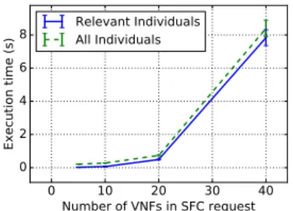
Fig. 5: Impact of the infrastructure size on MINLP based and semantic validation. 0 10 20 30 40 Number of VNFs in SFC request 0 2 4 6 8 Execution time (s) Relevant Individuals All Individuals
Fig. 6: Impact of the number of re-quested VNFs on the semantic valida-tion.
0 20 40 60 80
Number of constraints in SFC request 0.00 0.05 0.10 0.15 0.20 0.25 0.30 0.35 Execution time (s) Consistent SFCs Inconsistent SFCs All SFCs
Fig. 7: Impact of the number of con-straints per SFC on the semantic val-idation.
constraints. To select these locations, a discrete probability distribution with the following probability mass function is used for affinity restrictions (AS:0.6, DC:0.3, host:0.1) and anti-affinity restrictions (AS: 0.1, DC: 0.3, host: 0.6). The rationale behind this is that affinity constraints apply to more general location restrictions while for anti-affinity constraints, more granular specification of locations apply. The type of the constraints is uniformly distributed among the constraints defined in Section III. Table I lists the set ([x, y]) or ranges ([x−y]) for the various parameters that are set during the evaluations.
The Prot´eg´e editor6 was used to develop the SFC request modelling ontology using the OWL API7. Semantic Web Rule Language (SWRL)8 was used to express the aforementioned rules using concepts from the ontology defined in Section IV. The Prot´eg´e editor was also used to define the rules using the Manchester syntax9. The HermiT OWL Reasoner10 was used to check the consistency and the classification of the ontology. HermiT is a semantic reasoner for ontologies written in OWL. It is able to determine whether or not the ontology is consistent, identify subsumption relationships between classes, etc. The reasoner is based on a hypertableau calculus which provides efficient reasoning. The output of the reasoning process allows us to determine whether the SFC request at hand is valid or not. In the case of an invalid request, this is communicated to the requesting SP, otherwise the request is passed on to the embedding engine.
The evaluations were carried out using the STEVIN Su-percomputer Infrastructure at Ghent University11. The nodes are equipped with 2 Intel Xeon CPU E5-2680 v3 12-core processors and 32GB of physical memory. For the experi-ments, a single 2.5GHz core and 16GB of memory were requested. All evaluations were repeated 20 times with varying seed values, the graphs show the average values and 95%
confidence intervals.
6Prot´eg´e – http://protege.stanford.edu/ 7OWL2 – http://www.w3.org/TR/owl-features/ 8SWRL – http://www.w3.org/Submission/SWRL/
9Manchester – http://www.w3.org/2007/OWL/wiki/ManchesterSyntax 10HermiT OWL Reasoner – http://hermit-reasoner.com
11HPC UGent – http://www.ugent.be/hpc
Type Parameter Range
BRITE T opology #AS [2,3,4,5,8,16,32,64,128,256] #Neighbour-AS [2] #AS-Routers [8,16,32] #Neighbour-Routers [3] #DC [1,2,4] Intra-AS BW [5Gbps ... 50Gbps] Inter-AS BW [1Gbps ... 10Gbps] Intra-AS delay [5ms ... 10ms] Inter-AS delay [1ms ... 5ms] F at-tree T opology #Core switches [2,3] #Pods [1 ... 4]
#Servers per pod [5 ... 10] Link BW [5Mbps ... 10Mbps] Link delay [1ms] SFC #VNF [2,5,10,20,30,40] #Affinity constraints [5,10,20,40,60,80] Link BW [50Mbps ... 500Mbps] Segment delay [5ms ... 100ms] Processing delay [0ms ... 5ms]
TABLE I: Scenario parameters.
B. Scalability of Semantic SFC Validation
The mathematical formulation proposed in Section V can be adapted to validate affinity-constrained SFC requests by removing all resource constraints from the model. However, as indicated by the results in Figure 8, this approach scales poorly with increasing infrastructure sizes. The main reason for this is the increasing number of decision variables and constraints when modeling the validation using MINLP based solution. These experiments use a fixed number of 10 VNFs per SFC and5randomly generated affinity and anti-affinity restrictions. Furthermore, the exhaustive search that is performed when solving such a problem leads to execution times that increase exponentially with increasing infrastructure sizes. Modeling the problem using ontologies avoids having to check every possible placement, but instead allows to reason on the various constraints and their mutual impact. Nonetheless, also seman-tic reasoning times are known to increase exponentially with the number of individuals in the ontology. In Section IV, a se-mantic SFC request validation framework was discussed which loads both the substrate topology and requested SFC into an ontology. As shown in Figure 8, also the semantic validations suffers from exponentially increasing execution times when the infrastructure size grows. The semantic reasoning times can be significantly reduced when only including the relevant
parts of the infrastructure in the ontology. To determine these relevant parts, all physical locations of the substrate topology that are included in the SFC constraints are modeled. Further-more, also the parent locations are subsequently modeled. This set is typically much smaller than the complete infrastructure and can be considered constant for SFCs of the same size. When only loading relevant individuals, execution times show a constant trend at about 62ms, even when the infrastructure size increases.
Leaving out irrelevant parts of the infrastructure could have an impact on the accuracy and recall of identifying the inconsistent SFCs. Therefore, additional experiments are conducted taking the MINLP based solution as the ground truth and comparing the filtering results with those of the semantic request checker that only models relevant individuals. In the context of SFC validation, a false positive (FP) is an SFC that is considered to be invalid by the framework while in fact it is consistent, while a false negative (FN) is an SFC that is considered to be valid by the framework while in fact it is not. Filtering out valid SFCs, causing a high number of FPs, would be an unacceptable side-effect of the semantic filtering step. The proposed semantic solution based on OWL uses an Open World Assumption (OWA), meaning that in general no single agent or observer has complete knowledge, and therefore limits the kinds of inference and deductions it makes to those that follow from statements that are known to be true. Statements about knowledge that is not included in or inferred from the knowledge explicitly recorded in the system may be considered unknown, rather than wrong or false. Therefore, the semantic SFC checker will not consider an SFC to be invalid based on the absence of information about the topology. And thus, noFPs will be caused by filtering out irrelevant parts of the infrastructure. Validating 1000SFC requests using the output of the MINLP based solution yields
371 true positives (TPs),620 true negatives (TNs), 0 FPs and 9 FNs. As expected none of the SFCs are falsely marked as inconsistent by the semantic validation, leading to a precision of 100%. An example of constraints leading to a FN is a request requiring two VNFs to be located in a certain AS, while at the same time requesting them to be embedded in different DCs, when only a single DC is available in that AS. Due to the OWA, the semantic validation framework will not assume that the absence of such a DC in the ontology means that it does not exist, and therefore not mark the SFC as inconsistent.
Figure 6 shows the impact of increasing the requested SFC size on the semantic validation time. As can be expected, the execution time increases exponentially with an increasing number of VNFs per SFC. Validating SFC requests with
20 VNFs takes about 500 ms. Considering that we use a standard Hermit reasoner without optimizations on standard off-the-shelve hardware, this could be considered a reasonable processing overhead. As can be seen from the graph, only including the relevant substrate nodes has only a limited impact in this configuration, since we are considering substrate topologies with512nodes and5affinity restrictions per SFC.
To evaluate the impact of the number of affinity constraints on the semantic validation time, substrate topologies with
512 nodes were created and SFC requests with 10 VNFs instances were used. The number of randomly generated affinity constraints was varied from5to80. With an increasing number of constraints, the probability of inconsistencies in the SFC requests increases. Therefore, the average validation times for both groups of inconsistent and consistent SFC requests are shown separately. Figure 7 shows that the average validation times increase up to a certain point, after which they drop again. This behavior can be accounted to the fact that the probability of easy-to-detect conflicts (e.g., two contra-dictory constraints) increases when the number of constraints increases, quickly terminating the reasoning process. When the number of constraints is lower, the variety of constraint types and subjects on which they are posing these constraints is larger, leading to more complex conflicts that only appear when more information is inferred from the ontology, causing the validation to take more time. None of the SFCs with over
40 constraints is consistent, leading to an execution time of
0s for this subgroup.
C. Impact of Semantic Validation on Mapping Time
In this set of experiments we evaluate the impact on the mapping time when performing semantic validation on SFC sets prior to running the embedding algorithm. Furthermore, the share of the semantic validation step on the total execution time is evaluated. To this end, SFC request sets are generated where a certain percentage of SFCs has conflicting affinity constraints. The substrate topologies under consideration con-tain 512 nodes, while the request sets contain 20 SFCs, of which each SFC contains10VNFs and5 affinity restrictions. During this set of evaluations, the bandwidth minimization objective defined in Equation (31) is used.
Figure 8 shows the positive impact on the total mapping time per SFC request when semantically filtering the incon-sistent SFC requests out of the request set prior to performing the mapping step. The SFC requests are mapped as a set and contain20 SFC requests per set. By validating the SFC request set prior to mapping it, the total execution time can be reduced by 59% on average. Even when only 10% of the SFC requests are inconsistent, the execution times can be reduced with more than 25%. The relative execution time reduction approximately shows a logarithmic trend between
0% and 100% with an increasing number of inconsistent requests. These results show that it is beneficial to perform the semantic matching although it yields a small additional execution overhead when no inconsistent SFCs are present.
Figure 9 shows the same graph, but for the individual map-ping of100 SFC requests. On average, semantically filtering the request set reduces the mapping time with 50%. When no inconsistent SFC requests are present, there is an overhead incurred by the semantic matching step of 0.4%, which can be considered negligible compared to the total mapping time. For a 10% fraction of inconsistent SFCs per request set, the performance gain is about11%.
1932-4537 (c) 2016 IEEE. Personal use is permitted, but republication/redistribution requires IEEE permission. See http://www.ieee.org/publications_standards/publications/rights/index.html for more information. This article has been accepted for publication in a future issue of this journal, but has not been fully edited. Content may change prior to final publication. Citation information: DOI 10.1109/TNSM.2017.2681025, IEEE
Transactions on Network and Service Management
Fig. 8: Share of semantic matching and mapping on total execution time for SFC set mapping.
0.0 0.1 0.2 0.3 0.4 0.5 0.6 0.7 0.8 0.9 1.0 Percentage of inconsistent SFCs 0 10 20 30 40 50 60 70 80
Mapping Time vs Semantic Matching Time (s)
Consistent SFCs - mapping All SFCs - mapping
Fig. 9: Share of semantic matching and mapping on total execution time for individual SFC mapping.
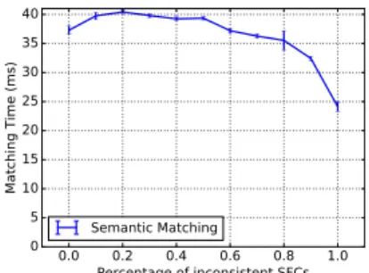
0.0 0.2 0.4 0.6 0.8 1.0 Percentage of inconsistent SFCs 0 5 10 15 20 25 30 35 40 Matching Time (ms) Semantic Matching
Fig. 10: Semantic matching execution time.
The previous graphs shows both the mapping and matching times. Figure 10 shows the matching time per SFC separately, note that the y-axis of this graph shows the time inmsinstead of s. As can be seen from the graph, the semantic filtering takes about 40ms but yields a benefit which is 28000 times greater in the case of set mapping and 355 times greater for individual request mapping.
0.0 0.2 0.4 0.6 0.8 1.0 Percentage of inconsistent SFCs 0 20 40 60 80 100 Percentage of SFCs mapped (%) Consistent SFCs All SFCs
Fig. 11: Percentage of SFC requests that are mapped. To assess the validity of the proposed semantic SFC vali-dation framework, also the number of mapped SFC requests was tracked when filtering out inconsistent SFCs, as well as when the complete SFC request set is considered for mapping. Figure 11 shows that every inconsistent SFC that was filtered out during the semantic matching process, was indeed impossible to map during the embedding phase due to inconsistencies in the request.
D. Performance of Heuristic Approach
Mapping the SFC request sets in a single step yields an increase in total execution time of the mapping process due to an increasing number of decision variables and constraints in the mathematical model. To alleviate these problems, a heuristic mapping procedure is proposed in which the different SFCs in the set are first ordered using a certain criterion, after which they are individually mapped onto the infrastructure. Figure 12 shows the impact of performing the heuristic proce-dure on the total execution time. During the experiments, both approaches are using the bandwidth minimization objective defined in Equation (31), the heuristic approach orders the SFCs according to the requested bandwidth criterion defined in Equation (34). The total execution time can be reduced
with a factor3378on average when performing the heuristic approach. The evaluations were performed using SFC request sets containing20SFCs and each SFC containing on average
5VNFs and 3affinity constraints. Mapping the SFC requests individually takes on average 0.85s, including the semantic matching.
The heuristic approach comes at a cost in optimality, since each request is considered individually, the global optimum is not achieved. Figure 13 shows the allocated bandwidth as a percentage of the total bandwidth available in the infras-tructure when minimizing the bandwidth usage. On average, the heuristic approach allocates 2.6% more bandwidth than the optimal solution. Also in terms of number of mapped SFC requests, the heuristic approach is outperformed by the optimal set mapping approach. Figure 14 shows that in some cases only 97.5% of the feasible SFC requests are mapped when applying the heuristic approach. This also implies that the resource consumption for the heuristic approach would be higher if the same amount of requests could be mapped.
E. Impact of Optimization Objective
Multiple optimization objectives were proposed in Sec-tion V. We compare the bandwidth minimizaSec-tion objective (MBW) proposed in Equation (31) with the load balancing objective (LBBW) of Equation (32). To compare the objec-tives, the maximum requested bandwidth for the virtual edges is varied. A set of 40 consistent SFC requests is generated and mapped onto the infrastructure resources. Figure 15 shows the impact of the objectives on the total resource usage. It is obvious that the LBBW optimization is outperformed in terms of total resource usage by MBW. Looking at the difference between the maximum and minimum load, shown in Figure 16, it is clear that the proposed balancing objective allows a better spread of the load compared to pure bandwidth optimization. Figure 17 shows the percentage of nodes that is used for the mapping, showing a higher node usage for LBBW. This graph also confirms that the load is spread across the infrastructure. The decrease in node usage with increasing bandwidth can be attributed to a reduced number of SFCs that can be mapped on the infrastructure due to capacity constraints.
40 50 60 70 80 90 100 110 Number of hosts 0 1000 2000 3000 4000 Mapping Time (s) Set Mapping - MBW Individual Mapping - MBW
Fig. 12: Total mapping time of Set mapping compared to Individual map-ping for increasing infrastructure size.
40 50 60 70 80 90 100 110 Number of hosts 8 10 12 14 16 18 20 22 24 26 Resource usage (%) Set Mapping - MBW Individual Mapping - MBW
Fig. 13: Objective of Set mapping compared to Individual mapping for increasing infrastructure sizes.
40 50 60 70 80 90 100 110 Number of hosts 66 68 70 72 74 Percentage of SFCs mapped (%) Set Mapping - MBW Individual Mapping - MBW
Fig. 14: Percentage of mapped SFCs when applying Set mapping compared to Individual mapping for increasing infrastructure sizes.
0 1000 2000 3000 4000 5000
Maximum requested bandwidth (Mbps) 1 2 3 4 5 Resource usage (%) MBW LBBW
Fig. 15: Total link bandwidth usage for various optimization objectives.
0 1000 2000 3000 4000 5000 Maximum requested bandwidth (Mbps) 40 50 60 70 80 90 100
Load difference (Max - Min) (%)
MBW LBBW
Fig. 16: Difference between the max-imum and minmax-imum link usage for various optimization objectives.
0 1000 2000 3000 4000 5000
Maximum requested bandwidth (Mbps) 45
50 55
Percentage of nodes used (%)
MBW LBBW
Fig. 17: Percentage of used nodes for various optimization objectives.
F. Impact of Ordering Criterion
To assess the impact of the ordering criteria proposed in Section VI, the experiments of the previous section were repeated for different criteria. The objective used is the band-width minimization objective. Each of the SFC requests has the same amount of affinity constraints attached to them. Fig-ure 18 shows the difference in acceptance rate when ordering based on the requested bandwidth, compared to ordering on the number of constraints. In this experiment, the number of constraints is constant, so ordering based on number of constraints falls back to an online processing behavior, where demands are taken one after another. Mapping the SFCs with the lowest bandwidth requirements first, increases the accep-tance rate significantly, since the load on the infrastructure is minimized.
0 1000 2000 3000 4000 5000 Maximum requested bandwidth (Mbps) 55 60 65 70 75 80 85 90 Percentage of SFCs mapped (%) Individual Mapping - NR_BW Individual Mapping - NC
Fig. 18: Impact of SFC ordering on acceptance rate. VIII. CONCLUSION ANDFUTUREWORK
This paper proposes a way for Service Providers (SPs) to attach location and colocation constraints to the mapping of Service Function Chains (SFCs) onto the substrate. These affinity constraints can be used to increase efficiency and
resilience, to adhere to legislative and privacy restrictions or for economic reasons. First, the different sets of affinity and anti-affinity constraints are formalized. Second, a semantic validation framework is proposed, which allows the Virtual Network Function Infrastructure Provider (VNFInP) to check the consistency of the constraints posed by the SFC requests. To this end, the substrate and the SFC request are modeled using an ontology of which the consistency is checked using a semantic reasoner. Finally, the SFC embedding problem subject to affinity constraints is formalized and an Integer Linear Programming (ILP) formulation for both set-based SFC and individual SFC mapping is proposed. The semantic validation and different mapping algorithms were evaluated thoroughly. By only loading the parts of the infrastructure that are relevant for the SFC request into the ontology, the number of individuals and thus the semantic reasoning time can be significantly reduced. Furthermore, by filtering out inconsis-tent SFC requests before mapping, the total execution time of the embedding algorithm can be reduced with more than
50% for the considered scenarios. Next to the set embedding formulation, also a heuristic approach is proposed in which the SFCs requests are embedded individually. To this end, the SFC requests are ordered based on certain criteria, after which the embedding is performed by solving the ILP.
In future work, alternative techniques for modeling the SFC mapping will be studied. For example, modeling it as a combined capacitated facility location-flow routing prob-lem allows greatly reducing the complexity compared to the modeling approach taken in this paper. By combining the proposed semantic filtering approach with more efficient mapping algorithms could potentially allow VNFInPs to find