County of Imperial
Oren R. Fox Medium Security Detention Facility – 270 Beds & Video Visitation / Print Shop
OAK #4812‐2759‐8120 v1 1. PARTICULARS 1.1 DATE: 9/17/15
1.2 PROJECT: County of Imperial The Oren R Fox Medium Security – 270 Beds and Video Visitation / Print Shop
1.3 OWNER: County of Imperial
1.4 B R I D G I N G A R C H I T E C T : V a n i r C o n s t r u c t i o n M a n a g e m e n t , I n c .
2. TO: DESIGN BUILDERS ‐ IMPERIAL COUNTY JAIL PROJECT (BIDDERS)
2.1 THIS ADDENDUM FORMS A PART OF THE CONTRACT DOCUMENTS AND MODIFIES THE BRIDGING DOCUMENTS ISSUED ON 8/28/15, ADDENDUM NO. 1 (4/02/15 BSCC ADDENDUM), WITH AMMENDMENTS AND ADDITIONS NOTED BELOW. THE FOLLOWING CHANGES SHALL BE INCORPORATED INTO AND SUPERSEDE AND/OR SUPPLEMENT THE BRIDGING DOCUMENTS & PREVIOUS ADDENDA WHEREVER THEY AND THE ADDENDUM CONFLICT.
2.2 Acknowledge receipt of all Addenda by inserting the addendum number and date in the space provided in Paragraph 1.04 of Document 00 4200 (Proposal Form) issued with the RFP. Failure to do so may subject Bidder to disqualification.
2.3 BIM Models and CAD files used to create the Bridging Documents are available for immediate distribution. Provide a signed Electronic Data Acceptance Waiver included in Section 00 0116.
2.4 THIS ADDENDUM CONSISTS OF 6 Pages and 10 attachments.
3. BRIDGING DRAWINGS (REVISIONS)
3.1 Revise Sheet A0.0 to read …MEDIUM SECURITY BUILDING ‐270 DORMITORY BEDS + 4 MEDICAL BEDS… in place of 228 Beds.
3.2 Revised A1.7 CONSTRUCTION STAGING PLAN see attachments
3.3 Remove AV2.1 located between AJ2.3 and AJ2.5 and replace with AJ2.4 UPPER LEVEL HOUSING FLOOR PLAN see attachments
4. CLARIFICATIONS :
4.1 Addendum #1 dated 4/02/15, was issued during the submittal phase to the BSCC. All drawings provided within Addendum #1 have been superseded by the Bridging Documents set distributed on August 28, 2015. Other items included in Addendum 1 such as review comments by the BSCC, review comments by the State Fire Marshall, and comments from County Public works shall all be resolved by the DBE.
4.2 Preproposal Meeting and Site Visit. See attachment.
4.3 Preproposal meeting instructions: The Imperial County Sheriff’s Office (ICSO) will not have any requirements/restrictions for specific “colors” of clothing that cannot be worn during the facility tour / site visit. Attendees should dress casual. Attendees should wear casual slacks or jeans, short sleeve shirts (it will be hot), do not wear open toed shoes, etc. If by chance there is
2 County of Imperial
Oren R. Fox Medium Security Detention Facility – 270 Beds & Video Visitation / Print Shop
ADDENDUM NUMBER 2 OAK #4812‐2759‐8120 v1 06729‐0001
to take our phones into the facility to take photos. However, I would encourage your team to bring a camera in the event the ICSO requests the attendees leave their phones outside the facility.
4.4 State Fire Marshall Comments and review has preliminarily approved the conceptual design to move forward with the Department of Finance approvals. It is the responsibility of the DBE to coordinate and respond to all review comments and any specific requirements by the State Fire Marshall including all requirements for fireproofing, occupancy separations, smoke separations, fire rated glazing, etc. The State Fire Marshall’s office will require the Design Build Team to submit an AMMR(Alternate Means and Methods Request) to show that Final design of the ‘Podium’/ Pedestal construction meets all code requirements and approval will be at the discretion of the Division Chiefs. The AMMR shall include specific information about the open stairs/ lobby condition within the ‘B’ Occupancy.
4.5 Note that the Architectural sheets show 2 stairways for exiting each of the cell tiers within the housing units, but many of the consultant drawings do not show the same stairway configuration. The dual stairway scenario is the only exiting scheme approved by the State Fire Marshall during the Design Development Phase. The Bridging Architect developed an earlier scheme which allowed for a door between 2 adjacent cell tiers to fulfil a second exit requirement based on occupant load on the cell tiers. This was not approved by the State Fire Marshall. It is the responsibility of the DBE to coordinate a final design which meets all applicable codes and complies with State Fire Marshall interpretations.
4.6 Architectural Space Program will not be made available to the Design Build Teams. 4.7 Imperial Irrigation District Engineering Review Comments by Samuel E. Singh, Project
Manager Sr. are to be resolved and incorporated into the final design by the DBE.
1. The overhead pole line and existing service appears to be in the way of your new construction. (see pdf with your proposed building overlapped on our mapping system labeled ‘IID review illustration.pdf’.) The three black circles are IID poles along the south side of your new construction. You had stated that the old service and pole line would be removed, but the customer must be sure that no other electrical services feed from the main panel being removed or they will be out of power.
2. The location of the transformer must be in a flat accessible area. The proposed transformer location next to the new main panel will not allow for access for our large trucks during installation or maintenance. We must relocate the transformer to the west; however the secondary wire cannot exceed 70’. The IID also suggests a flat wide area for trucks with a rolling gate for access off of Sperber Road. (see illustration in attached pdf labeled ‘IID review illustration.pdf’)
3. The existing pole location may be utilized for the new primary riser. This may happen if the overhead power line and existing service can be completely removed prior to installing the new service; this is a timing issue that would have to be resolved prior to initiation of project. If this cannot happen, the IID would utilize a new pole for the riser into the pad mounted transformer; this would be south of the existing pole.
County of Imperial
Oren R. Fox Medium Security Detention Facility – 270 Beds & Video Visitation / Print Shop
OAK #4812‐2759‐8120 v1
5. SPECIFICATIONS DIVISIONS 00 THROUGH 35 :
01 1119 RFP 3.01 E 10. c.
RFI: Is it acceptable to provide the Draft Management Plan in a separate 3 ring binder? A short summary will be included in the proposal response and each detailed plan in the appendix.
Response: Yes.
01 1119 RFP 3.01 E 10. Technical proposal Submission and 3.02 F Technical proposal organization RFI: Both sections E10 and F include Skilled Labor Force Availability and
Acceptable Safety record as evaluation factors. However, section 3.22 technical Proposal Submission, Skilled Labor Force Availability and acceptable Safety Record these factors are not required. Please clarify what is required in the Technical proposal Submission.
Response: The County has revised Section 3.01 E and F to remove Skilled Labor Force Availability and acceptable Safety Record.
01 1119 RFP 3.02 B proposed Design and Design Approach
RFI: Life cycle costs, it states that the proposer should submit a draft version of the Building Program report at the first confidential meeting. Please clarify if there will be any confidential meeting prior to the submission of proposal.
Response: There will not be any confidential meetings prior to the first submission of the proposal.
00 1119 RFP 4.03 A Interviews and Presentation pg 14
RFI: Section 00 1119 para. 4.03A states that the interviews will be undertaken during the week of October 12, 2015. Please advise the specific date and format of the interviews.
Response: The County will advise all proposers of the interview dates after receipt of proposals on October 9, 2015. The interviews will provide an opportunity for a dialogue between proposers and evaluators regarding those features of
proposers’ proposals that make them competitively superior to other proposals.
00 1119 Request for Proposals
Replace Document 00 1119 in its entirety with attached updated Request for Proposals
00 4200 Proposal Form 2.1
RFI: Please advise if each of the "TBD" Base Item amounts will be provided before submission of the proposals and will be included within the Stipulated Sum.
4 County of Imperial
Oren R. Fox Medium Security Detention Facility – 270 Beds & Video Visitation / Print Shop
ADDENDUM NUMBER 2 OAK #4812‐2759‐8120 v1 06729‐0001 00 4200 Proposal Form 2.1.3
RFI: Please advise if the [$100,000] amount shown in box brackets is intended to be an additive amount that is to be included in the Stipulated Sum.
Response: The $100,000 is not an additive amount to be included in the Stipulated Sum. For clarification, we have revised this line item on the Proposal Form.
00 4200 Proposal Form
Replace Document 00 4200 in its entirety with attached updated Proposal Form
00 4316 Bond Accompanying Proposal
RFI: Bond Accompanying proposal form lists the penal sum of the bond as the entire contract value. Please confirm that his bid bond should actually be 10% as stated in section 00 1119 para. 3.01E.2.
Response: Confirmed. The bid bond is 10% of the total proposed contract sum.
00 5200 Agreement pg 4 Section 2.04 Liquidated Damages
RFI: Clarify the amount for liquidated damages. It is shown as Seven thousand five hundred ($5000) per day.
Response: Liquidated damages are $5000 per day
00 7300 Annex 4 Project Management Plan
Replace Annex 4 in its entirety with updated Project Management Plan dated August 2015
00 7318 OCIP Manual
RFI: OCIP Manual para. 4.9 states that "Design‐Build Entity is further required to provide a full‐time qualified Safety Manager or designated competent safety representative who shall be onsite when any work is in progress". Please confirm that this Safety Manager can have other duties.
Response: Confirmed.
00 7349 Project Stabilization Agreement Proposers are advised that the Project Stabilization Agreement provided with the RFP materials is a draft document and may be subject to future changes. Imperial County is requesting that all prequalified DBE’s provide a list of their comments or concerns regarding the ICADF PSA document during the RFI period. As reflected on the amended Proposal Form (Document 00 4200) and amended Request for Proposals (Document 00 1119) attached to this Addendum, Imperial County also intends to seek pricing for the Project with and without the Project Stabilization Agreement. Proposers are notified that their Base Bid need not include the
County of Imperial
Oren R. Fox Medium Security Detention Facility – 270 Beds & Video Visitation / Print Shop
OAK #4812‐2759‐8120 v1
01 3100 Project Management and Coordination New Section provided. See attachment
01 3119 Project Meetings
New Section provided. See attachment
01 3300 Submittals
Reference Article 1.03 (A) (1) . Imperial County has NOT established “Primavera Contract Manager” for the purposes of electronic PROJECT communication. The DBE will BE RESPONSIBLE for providing their own web based project management software of ALL project communications/documents. DBE will provide licensing and training for the Owners use of the DBE’s software during design, construction and warranty periods. DBE’s should assume Owner will require training and licensing for up to 16 individuals. Refer to section 01 3100 SECTION 1.09 Project Information Management System for additional information.
01 3554 Building Information Modeling for Design Build New Section provided. See attachment
01 4519 Non Collusion Declaration
RFI: Clarify the number of the document is 00 4519 or is it 00 4520 as indicated on the form on pg 56 out of 722.
Response: The Non Collusion Declaration is Document 00 4520.
01 4520 Iran Contracting Act Certifications
RFI: Clarify the number of the document is 00 4520 or is it 00 4530 as indicated on the form on pg 57 out of 722.
Response: The Iran Contracting Act Certification is Document 00 4530.
01 4523 Quality Requirements para 1.14A
RFI: para. 1.14A states that "The Owner’s Construction Manager will employ and pay for services of an independent testing laboratory" . Spec 00 7253 para. 2.04R states that "Design‐Build Entity shall provide to Owner all tests and
measurements, laboratory analyses, and reports made or prepared in connection with the Work". Please confirm that Testing Agency services are provided by and paid for by the Owner.
Response: Confirmed.
07 5300 Mechanically Attached Membrane Roofing
Add Carlisle Syntec Systems as an approved Manufacturer of Membrane Roofing.
6 County of Imperial
Oren R. Fox Medium Security Detention Facility – 270 Beds & Video Visitation / Print Shop
ADDENDUM NUMBER 2 OAK #4812‐2759‐8120 v1 06729‐0001 ‘no substitutions’.
08 3463 Detention Door and Frames
Add Slate Security as an approved manufacturer of Detention Doors and Frames.
ATTACHMENTS WITH THIS ADDENDUM:
A1.7 CONSTRUCTION STAGING PLAN AJ2.4 UPPER LEVEL HOUSING FLOOR PLAN 00 1119 Request for Proposals
00 4200 Proposal Form
00 7300.4 Annex 4 –Project Management Plan 01 3100 Project Management and Coordination 01 3119 Project Meetings
01 3554 Building Information Modeling for Design Build Preproposal Meeting and Site Visit
IID Review Illustration
END OF ADDENDUM NO. 2
UP UP UP UP UP UP UP UP P t. 2 9 8 0 .7 6 t. 8 .0 5 E D G E M A T C H T O S H E E T 3 S H E E T 2 O F 3 C .A .S . 9 8 0 8 1 0 8 -1 1 -9 8 C .I .1 ' 1 "= 4 0 ' " S IT E 1 -E l C e n tr o , C A " C o u n ty o f Im p e r ia l, C A T a n k S ig n E D G E M A T C H T O S H E E T 2 S ig n M .H . M .H . M .H . M .H . M .H . M .H . M .H . M .H . M .H . ELECT. BOX R/W R/W 978 9 7 7 9 7 7 977 978 978 9 7 8 9 7 7 97 6 9 7 8 9 7 8 978 976 976 977 977 977 977 976 977 976 977 978 9 7 8 9 7 8 978 97 7 9 7 8 9 78 978 97 7 9 7 7 9 7 8 978 976 9 7 8 9 7 6 978 978 9 76 9 7 8 9 7 8 978 978 978 EB EB EB C LF C LF 60.0' R/W 20.0' R/W TO CL 60.0' R/W 30.0' CL 30.0' CL
Sperber Rd
(E) Adult Detention
Facility
(E) Medium Security
Facility
(E
)
P
ro
p
e
rt
y
L
in
e
P R O P O S E D P R O P E R T Y L IN E(E) PROPERTY LINE
(E) Property Line
INMATE / FOOD SERVICE CIRCULATION: CONTRACTOR MUST PROVIDE
UNINTERRUPTED ACCESS DURING CONSTRUCTION ACTIVITIES. PROVIDE TEMPORARY PAVING AS REQUIRED FOR FOOD SERVICE INMATE CIRCULATION. 16' HIGH TEMPORARY
SECURITY FENCING - TYPICAL
EXISTING PERSONNEL & VEHICLE GATE(S) FOR ICSO USE ONLY
CM / ICSO TRAILER
CONTRACTOR PARKING
& STAGING AREA
CONTRACTOR TO FURNISH AND INSTALL 16' H TEMPORARY SECURITY FENCING, PERSONNEL GATES, VEHICULAR GATES, RAZOR WIRE AS NOTED ON STAGING PLAN. INSTALL FULL HEIGHT SCREENING FABRIC ON THE OUTSIDE OF ALL "SECURITY" FENCING - TYPICAL (ALL IDENTIFIED FENCING ADJACENT TO EXISTING JAIL FACILITIES.) INSTALL TEMPORARY GRANULAR BASE, RELOCATE EXISTING EQUIPMENT FOR USE OF PARKING & STAGING AREA. STAGING AREAS TO BE CLEARED, REGRADED AND RETURNED TO LIKE NEW CONDITION.
CONTRACTOR STAGING PLAN SUBJECT TO APPROVAL BY ICSO - TYPICAL. NEW TEMPORARY VEHICLE SECURITY GATES BY DBE TO MATCH EXISTING PERIMETER SECURITY FENCING. GATES MUST BE LOCKED / SECURED DURING ALL NON-WORKING HOURS.
CONSTRUCTION TRAFFIC
NO CONTRACTOR ACCESS DURING CONSTRUCTION NO CONTRACTOR ACCESS DURING CONSTRUCTION
CONTRACTOR SHALL INSTALL FULL HEIGHT SCREENING FABRIC ALONG THE OUTSIDE OF ALL EXISTING SECURITY FENCING LOCATED ALONG EXISTING TEMPORARY CONSTRUCTION ACCESS - TYPICAL
IMPERIAL COUNTY
STORAGE / STAGING
AREA
NEW TEMPORARY VEHICLE SECURITY GATES BY DBE TO MATCH EXISTING PERIMETER SECURITY FENCING. GATES MUST BE LOCKED / SECURED DURING ALL NON-WORKING HOURS.
CONSTRUCTION TRAFFIC
NO CONTRACTOR ACCESS DURING CONSTRUCTION PARKING IN DESIGNATED
CONTRACTOR PARKING AREAS ONLY. UNAUTHORIZED CONTRACTOR
PARKING WILL RESULT IN THE TOWING OF VEHICLE(S) AT THE OWNERS EXPENSE. TYPICAL - ALL LOTS.
CONTRACTOR TO PROVIDE 6' HIGH TEMPORARY CONSTRUCTION
FENCING W/ (3) STRANDS BARD WIRE AND SCREENING - TYPICAL AT VIDEO VISITATION / PRINT SHOP SITE.
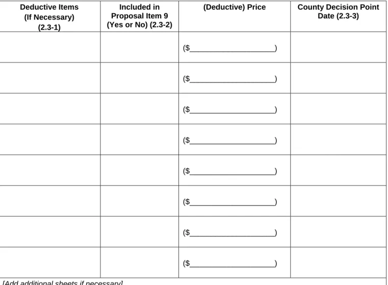
DA3: TEMPORARY CONSTRUCTION FENCING SHALL BE ELMINATED FOR THIS DEDUCTIVE ALTERNATE.
CONTRACTOR PARKING
& STAGING AREA
VEHICLE ACCESS FROM INSIDE LOOP ROAD ONLY. CONTRACTOR SHALL BE RESPONSIBLE FOR ALL TEMPORARY FACILITIES. UPON COMPLETION OF PROJECT ALL TEMPORARY STAGING AREAS TO BE CLEARED, REGRADED AND RETURNED TO LIKE NEW CONDITION.
Loop Rd
A
p
p
le
s
ti
ll
R
d
PARKING IN DESIGNATEDCONTRACTOR PARKING AREAS ONLY. UNAUTHORIZED CONTRACTOR
PARKING WILL RESULT IN THE TOWING OF VEHICLE(S) AT THE OWNERS EXPENSE. TYPICAL - ALL LOTS.
ICSO
TRANSITION
TEAM
CONSTRUCTION TRAFFIC
CONSTRUCTION TRAFFIC
CONTRACTOR IS RESPONSIBLE FOR TEMPORARY SECURITY LIGHTING WITHIN NEW AND EXISTING FACILITIES DURING CONSTRUCTION. A WELL LIT AND SECURE PERIMETER MUST BE
MAINTAINED AND COORDINATED WITH THE OWNER THROUGHOUT ALL CONSTRUCTION ACTIVITIES DBE CONSTRUCTION TRAILER
PRINT SHOP TO REMAIN IN USE BY ICSO
INMATE
RECREATION
AREA
NEW TEMPORARY VEHICLE SECURITY GATES BY DBE TO MATCH EXISTING PERIMETER SECURITY FENCING. GATES MUST BE LOCKED / SECURED DURING ALL NON-WORKING HOURS
TEMPORARY SECURITY / WORK LIGHTING - TYPICAL (LOCATIONS & SPACING TO BE APPROVED BY ICSO)
CONTRACTOR PARKING AREA
TWO (2) ROWS -16' H TEMPORARY SECURITY FENCING THIS AREA
TEMPORARY SECURITY / WORK LIGHTING - TYPICAL (LOCATIONS & SPACING TO BE APPROVED BY ICSO)
TEMPORARY SECURITY / WORK LIGHTING - TYPICAL (LOCATIONS & SPACING TO BE APPROVED BY ICSO)
TEMPORARY SECURITY / WORK LIGHTING - TYPICAL (LOCATIONS & SPACING TO BE APPROVED BY ICSO)
TEMPORARY SECURITY / WORK LIGHTING - TYPICAL (LOCATIONS & SPACING TO BE APPROVED BY ICSO)
CONTRACTOR TO PROVIDE 6' H
TEMPORARY CONSTRUCTION FENCING W./ (3) STRANDS BARB WIRE AND SCREENING AT CONTRACTOR PARKING & STAGING AREA
Phase: Drawn By: Checked By: Job No.: Issue Date:
THIS DOCUMENT IS COPYRIGHT MATERIAL, ANY DISCLOSURE, UNAUTHORIZED USE, DISSEMINATION OR DUPLICATION WITHOUT THE EXPRESS WRITTEN CONSENT OF VANIR
CONSTRUCTION MANAGEMENT IS PROHIBITED. ALL RIGHTS RESERVED.
PRELIMINARY DESIGN.
FOR DESIGN BUILD RFP.
NOT FOR CONSTRUCTION.
8/12/15
RFP ISSUE
B :\ P P ro je c ts \T 4 4 3 I m p e ri a l C o u n ty B ri d g in g D o c s \R e v it \I C S it e \I C S it e _ N e w P a rk in g L o t. rv t 9 /1 /2 0 1 5 9 :3 2 :2 7 A M Author 08/12/15T
h
e
O
re
n
R
.
F
o
x
M
ed
iu
m
S
ec
u
ri
ty
2
7
0
B
ed
s
&
V
id
eo
V
is
it
at
io
n
/
P
ri
n
t
S
h
o
p
C
o
u
n
ty
o
f
Im
p
er
ia
l
-
A
B
9
0
0
N
ew
M
ed
iu
m
S
ec
u
ri
ty
D
et
en
ti
o
n
F
ac
il
it
y
T443Site Staging Plan
A1.7
Checker T h e O re n R . F o x M e d iu m S e c u ri ty 2 7 0 B e d s & V id e o V is it a ti o n / P ri n t S h o p A 1 .7 S it e S ta g in g P la nBRIDGING
DOCUMENTS
3
2
8
A
p
p
le
st
il
l
R
d
.
E
l
C
en
tr
o
C
a
9
2
2
4
4
1" = 50'-0"
1
SITE STAGING PLAN
Revision Schedule # Date Description
Oren R. Fox Medium Security Detention Facility 01 3119 - 1 Project Meetings
OAK #4818-6580-1762 v2
DIVISION 1 GENERAL REQUIREMENTS SECTION 01 3119
PROJECT MEETINGS (Design-Build) PART 1 – GENERAL
1.01 Summary
A. Section includes description of required project meetings for construction phase of the Work.
B. Meetings are in addition to design phase and other pre-construction phase meetings required by
Contract Documents
1.02 Preconstruction Conference
A. Preconstruction Conference. Owner will call for and administer Preconstruction Conference at
time and place to be announced (usually the week prior to start of Work at the Site).
B. Design Build Entity, all major Subcontractors, and major suppliers shall attend Preconstruction
Conference. Agenda may include, but not be limited to, the following items (to the extent not previously resolved):
1. Schedules
2. Design Build Entity’s Initial Progress Schedule
3. Design Build Entity’s Schedule of Values
4. Design Build Entity’s Schedule of Submittals
5. Security
6. Personnel security clearance procedures
7. Use of premises
8. Location of the Design Build Entity’s on-site facilities
9. Housekeeping
10. Submittal and RFI procedures
11. Inspection and testing procedures, on-Site and off-Site
12. Utility shutdown procedures
13. Control and reference point survey procedures
14. Safety
15. Jurisdictional agency requirements
C. Owner DBE will distribute copies of minutes to attendees. Attendees shall have 7 Days to submit
comments or additions to minutes. Minutes will constitute final memorialization of results of Preconstruction Conference.
1.03 Schedule Review Meeting
A. Refer to Section 01 3200 Progress Schedules and Reports for required schedule meetings.
1.04 Weekly Project Meetings
A. Owner will schedule and administer weekly progress meetings throughout duration of Work’s
construction phase. Progress meetings will be held weekly unless otherwise directed by Owner. Meetings shall be held at Owner’s Offices unless otherwise specified in Contract Documents.
1. Owner’s Representative will prepare agenda and distribute it 4 Days one Day in advance of
Oren R. Fox Medium Security Detention Facility 01 3119 - 2 Project Meetings
OAK #4818-6580-1762 v2
2. Participants with agenda items shall present them.
3. Owner DBE shall record and distribute the meeting minutes. Minutes shall be distributed
by the Owner DBE to the DBE Owner within 3 business days after the meeting. Design Build Entity shall distribute the minutes to those affected by decisions made at meeting. Attendees shall have five business days to submit comments or additions to the minutes. Minutes shall constitute final memorialization of results of meeting.
4. Progress meetings shall be attended by Design Build Entity’s job superintendent, major
Subcontractors and suppliers, principle Designers, Owner, Owner consultants and Bridging Architect (at Owner’s option), and others as appropriate to agenda topics for each meeting.
5. Agenda may contain the following items, as appropriate:
a. Review, revise as necessary, and approve previous meeting minutes
b. Review of Work progress since last meeting
c. Status of Construction Work Schedule, delivery schedules, adjustments
d. Submittal, RFI, and Change Order status
e. Review of the Design Build Entity’s safety program activities and results, including report on all serious injury and/or damage accidents
f. Other items affecting progress of Work
1.05 Progress Schedule and Billing Meetings
A. Refer to Sections 01 2000 (Measurement and Payment) and 01 3200 (Progress Schedules and
Reports) for Progress Schedule and Billing Meetings.
1.06 Special Meetings
A. Any party may call special meetings by notifying all desired participants and Owner two (2) Days
in advance, giving reason for meeting. Special meetings may be held without advance notice in emergency situations.
B. At any time during the progress of Work, Owner shall have authority to require Design Build Entity
to schedule a meeting with Owner and of any or all of the Subcontractors engaged in Work or in other work, to address matters of concern to the Owner.
C. Design Build Entity shall schedule and conduct coordination meetings as necessary to discharge
coordination responsibilities in Document 00 7253 (General Conditions). Design Build Entity shall give Owner Five (5) two (2) Days written notice of coordination meetings. Design Build Entity shall maintain minutes of coordination meetings. Attendees shall have seven (7) Days to submit comments or additions to minutes. Minutes will constitute final memorialization of results of coordination meetings.
D. Design Build Entity to submit minutes of meetings to all attendees within three (3) days of the meeting in a format acceptable to the Owner.
1.07 Safety Meetings
A. Conduct Design Build Entity Safety Committee meetings as stipulated in Design Build Entity’s
Safety Plan and (as applicable) Document 00 7319 (Owner Controlled Insurance Program Safety Standards Manual).
PART 2 – PRODUCTS – NOT USED PART 3 – EXECUTION – NOT USED
SECTION 013100
PROJECT MANAGEMENT AND COORDINATION
PART 1 - GENERAL
1.01 RELATED DOCUMENTS
A. Drawings and general provisions of the Contract, including General and Supplementary Conditions and other Division 01 Specification Sections, apply to this Section. 1.02 SUMMARY
A. Section includes administrative provisions for coordinating construction operations on Project including, but not limited to, the following:
1. General coordination procedures. 2. Coordination drawings.
3. Requests for Information (RFI’s). 4. Project Web site.
5. Project meetings.
B. Design Build Entity shall participate in coordination requirements. C. Related Requirements:
1. Section 013200 "Construction Progress Documentation" for preparing and submitting Design Build Entity's construction schedule.
2. Section 017300 "Execution" for procedures for coordinating general installation and field-engineering services, including establishment of benchmarks and control points. 3. Section 017400 “Construction Waste Management and Disposal” for additional waste
salvage requirements. from
4. Section 017700 "Closeout Procedures" for coordinating closeout of the Contract. 5. Section 019110 "General Commissioning Requirements" for coordinating the Work
with Owner's Commissioning Authority. 1.03 DEFINITIONS
A. RFI: “Request for Information:” Means a formal written request submitted by Design Build Entity for clarification of what it perceives to be a discrepancy in the Contract Documents (including, without limitation, information in the Contract Documents constituting a Design Discrepancy or a variance between the information in the Bidding Documents or Contract Documents and conditions at the Site or in Existing improvements).
1.04 ADMINISTRATIVE REQUIREMENTS
A. Process: The Architect, Design Build Entity and Construction Manager shall use the DBE’s web-based Project Information Management System, , for tracking and responding to all items identified in Specification Section 013100-1.09 “Information Management System”. Forms included in the Project Manual are printed facsimiles of the response forms that should be used by the project team. DBE shall provide the County and it’s CM full access to their web-based Project Information Management System. DBE shall procure additional licenses and provide the needed training as required for utilization by the County Representative and the Construction Manager.
1. Design Build Entity shall prepare requests and submittals on electronic forms acceptable to Architect, Construction Manager and Owner provided the data included is consistent with the forms included at the end of this Section.
1.05 INFORMATION SUBMITTALS
A. Subcontract List: Prepare a written summary identifying individuals or firms proposed for each principal portion of the Work, including those who are to furnish materials or equipment fabricated to a special design. Use electronic facsimile of CSI Form 1.5A. Include the following information in tabular form:
1. Name, address, and telephone number of entity performing subcontract or supplying products.
2. Number and title of related Specification section(s) covered by subcontract. 3. Drawing number and detail references, as appropriate, covered by subcontract. B. Print Coordination Drawing: Submit two (2) opaque copies of each submittal. Architect,
through Construction Manager, will return one (1) copy.
1. Submit five (5) copies where Coordination Drawings are required for Operation and Maintenance Manuals. Construction Manager will retain two (2) copies; remainder will be returned. Mark up and retain one (1) returned copy as a Project Record Drawing.
C. Digital Coordination Drawings: Two-dimensional documents or BIM documents, such as schedules, shop drawings, product data, and general information, shall be submitted electronically in portable document format (PDF) file and uploaded to Project Web site.Key Personnel Names: Within fifteen (15) Working Days of starting construction operations, submit a list of key personnel assignments, including superintendent and other personnel in attendance at Project site. Identify individuals and their duties and responsibilities; list addresses and telephone numbers, including office, and cellular telephone numbers and e-mail addresses. Provide names, addresses, and telephone numbers of individuals assigned as alternates in the absence of individuals assigned to Project.
1. The Construction Manager shall post copies of list in project meeting room, in the Owner’s temporary field office, on Project Web site, and by each temporary telephone. The Design Build Entity shall keep their list current and provide an updated list to the Construction Manager when changes occur.
1.06 GENERAL COORDINATION PROCEDURES
A. Coordination: Coordinate construction operations included in different Specification sections to ensure efficient and orderly installation of each part of the Work. Coordinate construction operations, included in different sections that depend on each other for proper installation, connection, and operation.
1. Schedule construction operations in sequence required to obtain the best results where installation of one part of the Work depends on installation of other components, before or after its own installation.
2. Coordinate installation of different components to ensure maximum performance and accessibility for required maintenance, service, and repair.
3. Make adequate provisions to accommodate items scheduled for later installation. B. Coordination: Design Build Entity shall coordinate each Subcontractor to ensure efficient and
orderly installation of each part of the Work. Design Build Entity and Subcontractors shall coordinate its operations with operations included in different sections that depend on each other for proper installation, connection, and operation.
1. Schedule construction operations in sequence required to obtain the best results where installation of one part of the Work depends on installation of other components, before or after its own installation.
2. Coordinate installation of different components with other contractors to ensure maximum performance and accessibility for required maintenance, service, and repair.
3. Make adequate provisions to accommodate items scheduled for later installation. C. Prepare memoranda for distribution to each party involved, outlining special procedures
required for coordination. Include such items as required notices, reports, and list of attendees at meetings.
1. Prepare similar memoranda for Construction Manager, Owner and separate subcontractors if coordination of their Work is required.
D. Administrative Procedures: Coordinate scheduling and timing of required administrative procedures with other construction activities and activities of other contractors and subcontractors to avoid conflicts and to ensure orderly progress of the Work. Such administrative activities include, but are not limited to, the following:
1. Preparation of Design Build Entity's construction schedule. 2. Preparation of the Schedule of Values.
3. Installation and removal of temporary facilities and controls. 4. Delivery and processing of submittals.
5. Progress meetings.
6. Pre-installation conferences. 7. Project closeout activities.
8. Startup and adjustment of systems.
E. Conservation: Coordinate construction activities to ensure that operations are carried out with consideration given to conservation of energy, water, and materials. Coordinate use of temporary utilities to minimize waste.
1. Salvage materials and equipment involved in performance of, but not actually incorporated into, the Work. See other sections for disposition of salvaged materials that are designated as Owner's property.
1.07 COORDINATION DRAWINGS
A. Coordination Drawings, General: Prepare color coded coordination drawings according to requirements in individual Sections, and additionally where installation is not completely shown on Shop Drawings, where limited space availability necessitates coordination, or if coordination is required to facilitate integration of products and materials fabricated or installed by more than one entity.
1. Content: Project-specific information, drawn accurately to a scale large enough to indicate and resolve conflicts. Do not base coordination drawings on standard printed data. Include the following information, as applicable:
a. Use applicable Drawings as a basis for preparation of coordination drawings. Prepare sections, elevations, and details as needed to describe relationship of various systems and components.
b. Coordinate the addition of trade-specific information to the coordination drawings by subcontractors in a sequence that best provides for coordination
of the information and resolution of conflicts between installed components before submitting for review.
c. Provide coordinated, color coded composite drawings, drawn at a scale not less than 1/4 inch per foot in both plan and elevation, including, but not limited to, equipment, ducts, pipe sleeves, piping including plumbing and sprinkler systems, lighting, special supports and other items contained within the space and finished ceiling. Show mechanical and electrical services and architectural and structural features drawn to scale. Provide composite drawings for all project areas. Distribute copies of composite drawings to all trades to assure a complete, coordinated installation of work within the space available. Include elevation drawings indicating finish ceiling heights, and heights above finished floor to bottom of ductwork, piping, conduit and other overhead fixtures and equipment.
1) Sheet Size: At least 11 by 17 inches but no larger than 30 by 42 inches. 2) Draw required details at a scale not less than 3/4 inch per foot.
d. Indicate functional and spatial relationships of components of architectural, structural, civil, mechanical, and electrical systems.
e. Indicate space requirements for routine maintenance and for anticipated replacement of components during the life of the installation.
f. Show location and size of access doors required for access to concealed dampers, valves, and other controls.
g. Indicate required installation sequences.
1) Scheduling, sequencing movement, and positioning of large equipment into the building during construction.
h. Indicate dimensions shown on the Drawings. Specifically note dimensions that appear to be in conflict with submitted equipment and minimum clearance requirements. Provide alternate sketches to Architect indicating proposed resolution of such conflicts. Minor dimension changes and difficult installations will not be considered changes to the Contract.
i. Refer to Sections of Division 23 and Division 26 for specific Coordination j. Drawing requirements for mechanical and electrical installations.
k. Indicate relationship of components shown on separate Shop Drawings. B. Coordination Drawing Organization: Organize coordination drawings as follows:
1. Floor Plans and Reflected Ceiling Plans: Show architectural and structural elements, and mechanical, plumbing, fire-protection, fire-alarm, and electrical Work. Show locations of visible ceiling-mounted devices relative to acoustical ceiling grid. Supplement plan drawings with section drawings where required to adequately represent the Work. Designate fire-rated walls, partitions and floors.
a. Where indicated, include supports, components and plenum space clearances for raised access flooring.
2. Plenum Space: Indicate sub-framing for support of ceiling and wall systems, mechanical and electrical equipment, and related Work. Locate components within ceiling plenum to accommodate layout of light fixtures indicated on Drawings. Indicate areas of conflict between light fixtures and other components.
4. Mechanical, Electrical, Security Electronics, MDF and IDF Rooms: Provide coordination drawings for mechanical, electrical, MDF, IDF and security electronics rooms showing plans and elevations of mechanical, plumbing, security electronics, fire-protection, fire-alarm, and electrical equipment.
5. Structural and Through Penetrations: Indicate fire-rated and non-fire-rated penetrations and openings required for all disciplines through interior and exterior walls, interior partitions, foundation walls, and floor slabs.
6. Slab Edge and Embedded Items: Indicate slab edge locations and sizes and locations of embedded items for metal fabrications, sleeves, anchor bolts, curtain wall anchorage, bearing plates, angles, door floor closers, slab depressions for floor finishes, curbs and housekeeping and equipment pads, and similar items.
7. Mechanical and Plumbing Work: Show the following:
a. Sizes and bottom elevations of ductwork, supply piping, sanitary, floor and roof drain piping, heat tracing, vacuum system piping and conduit runs, including insulation, bracing, flanges, and support systems. Indicate access points and required maintenance areas.
b. Dimensions of major components, such as master-trol components, control boxes, dampers, valves, diffusers, access doors, cleanouts and electrical distribution equipment.
c. Fire-rated enclosures around ductwork. d. Sleeves and capped utilities for future work. 8. Electrical Work: Show the following:
a. Runs of vertical and horizontal conduit 1inch (25 mm) in diameter and larger. b. Light fixture, exit light, electrified door hardware, access controls, emergency
battery pack, smoke detector, and other fire-alarm locations.
c. Panel board, switch board, switchgear, transformer, busway, generator, and motor control center locations.
d. Location of pull boxes and junction boxes, dimensioned from column center lines.
e. Ladder trays and racks.
9. Fire-Protection System: Show the following:
a. Locations of pumps, standpipes, mains piping, branch lines, pipe drops, and sprinkler heads.
10. Site Work: Show the following:
a. Civil and electrical underground utilities, both new and existing. b. Location of all building and site ground connections and rods.
11. Review: Construction Manager will review coordination drawings to confirm that the Work is being coordinated, but not for the details of the coordination, which are Design Build Entity's responsibility. If Construction Manager determines that coordination drawings are not being prepared in sufficient scope or detail, or are otherwise deficient, Architect will so inform Design Build Entity, through the Construction Manager, and Design Build Entity shall make changes as directed and resubmit.
C. Coordination Drawing Prints: Prepare coordination drawing prints according to requirements in Section 013300 "Submittal Procedures."
D. Coordination Digital Data Files: Prepare coordination digital data files according to the following requirements:
1. File Preparation Format: Same digital data software program, version, and operating system as original Drawings.
2. File Submittal Format: Submit or post coordination drawing files using Portable Data File (PDF) format.
3. BIM File Incorporation: Develop and incorporate coordination drawing files into Building Information Model established for Project. See Specification section 013554 “Building Information Modeling (BIM)”.
a. Perform three-dimensional component conflict analysis as part of preparation of coordination drawings. Resolve component conflicts prior to submittal. Indicate where conflict resolution requires modification of design requirements by Architect.
4. Criteria Architect will furnish to the Design Build Entity, through the Construction Manager, one set of digital data files of Drawings.
a. Criteria Architect makes no representations as to the accuracy or completeness of digital data files as they relate to Drawings.
b. Digital Data Software Program: Drawings are available in Revit 2015 and AutoCAD 2015.
c. Design Build Entity shall execute an electronic data licensing agreement. d. Electronic Data Transfer Agreement included at the end of Section 017839
Project Record Documents. 1.08 REQUESTS FOR INFORMATION (RFI’s)
A. General: Immediately on discovery of the need for additional information or interpretation of the Contract Documents, Contractor shall prepare and submit to the Construction Manager, utilizing the web based Information Management System, an electronic RFI in the form specified.
1. RFI’s will be returned to the Design Build Entity for re-submission, when RFI’s are not submitted to the Construction Manager through the Web Site Information Management System,.
2. Coordinate and submit RFI’s in a prompt manner so as to avoid delays in Design Build Entities work or work of Subcontractors.
3. Limit each RFI to one subject.
4. Submit an RFI if one of the following conditions occur:
a. Design Build Entity discovers an unforeseen condition or circumstances that is not described in the Contract Documents.
b. Design Build Entity discovers an apparent conflict or discrepancy between portions of the Contract Documents that appears to be inconsistent or is not reasonably inferred from the intent of the Contract Documents.
c. Design Build Entity discovers what appears to be an omission from the Contract Documents that cannot be reasonably inferred from the intent of the Contract Documents.
B. Content of the RFI: Include a detailed, legible description of item needing information or interpretation and the following:
2. Project number 3. Date
4. Name of Design Build Entity/Subcontractor
5. RFI number, numbered sequentially starting with 0001 (4-digits). Follow RFI with sequential Revision suffix as necessary for each resubmission. For example, the first RFI would be 0001. The second RFI would be 0002. The first resubmittal of RFI 0002 would be 0002-R1.
6. RFI subject
7. Specification Section number and title and related paragraphs, as appropriate. 8. Drawing number and detail references, as appropriate.
9. Field dimensions and conditions, as appropriate. 10. Location and/or building.
11. Discipline related to the RFI.
12. Design Build Entity's suggested resolution: If Design Build Entity's suggested resolution impacts the Contract Time or the Contract Sum, Design Build Entity shall state impact in the RFI.
13. Attachments: Include sketches, descriptions, measurements, photos, Product Data, Shop Drawings, coordination drawings, and other information necessary to fully describe items needing interpretation.
a. Include dimensions, thicknesses, structural grid references, and details of affected materials, assemblies, location, building discipline (i.e., Mechanical) and attachments on attached sketches.
C. RFI Forms: Use electronic facsimile of RFI Form included at the end of this Section. The RFI Form will automatically be filled out when entering an RFI onto the Project Web site .
1. Attachments shall be electronic files in Adobe Acrobat PDF format.
D. Architect's Action: Architect, through the Construction Manager, will review each RFI, determine action required, and respond. Allow seven (7) Working Days for Architect's response for each RFI. RFI’s received by Construction Manager after 1:00 p.m. will be considered as received the following working day.
1. The following Design Build Entity-generated RFI’s will be returned without action: a. Incomplete RFI’s or inaccurately prepared RFI’s.
b. Requests for approval of submittals. c. Requests for approval of substitutions.
d. Requests for approval of Design Build Entity's means and methods.
e. Requests for coordination information already indicated in the Contract Documents.
f. Requests for adjustments in the Contract Time or the Contract Sum. g. Requests for interpretation of Architect's actions on submittals. h. Requests that are a statement or a contractual issue.
i. Requests submitted as an alternative to: 1) Reading manufacturer’s instructions,
2) Consulting references or industry standards cited by the Contract Documents
j. Requests submitted in an untimely manner without proper coordination and scheduling of Work of related trades.
2. Architect's action may include a request for additional information, in which case Architect's time for response will date from time of receipt of additional information. 3. All Architect’s actions for RFI’s pertaining to Fire & Life Safety issues must be
reviewed by the State Fire Marshal prior to final approval and/or implementation of action. These responses may require additional time for required approvals.
4. Architect's action on RFI’s that may result in a change to the Contract Time or the Contract Sum may be eligible for Design Build Entity to submit Notice of Change according to Section 012600 "Contract Modification Procedures."
a. If Design Build Entity believes the RFI response warrants change in the Contract Time or the Contract Sum, notify Construction Manager in writing within three (3) Working Days of receipt of the RFI response, utilizing a Notice of Change (NOC) document. Within fourteen (14) Days of the NOC, a Change Order Request (COR) document must be submitted to the Construction Manager.
E. RFI Log: Shall be maintained by the DBEwithin the Web Site Information Management System,.
F. On receipt of Architect's RFI response the Construction Manager will update the RFI log. Design Build Entity shall upon receipt of RFI response immediately distribute the RFI response to affected parties. Review response and notify Architect, through the Construction Manager, within seven (7) Working Days if Design Build Entity disagrees with response. G. Should Design Build Entity proceed with Work affected before receipt of a response from the
Architect, within the response time described above, any portion of the Work which is not done in accordance with the Architect’s interpretations, clarifications, instructions, or decisions is subject to removal or replacement and Design Build Entity shall be responsible for all resultant losses.
H. Design Build Entity shall not use the quantity of RFI’s as justification for additional compensation or extensions of time.
1.09 PROJECT INFORMATION MANGAMENT SYSTEM
A. Design Build Entity shall provide a web based Project Information Management System for purposes of hosting and managing project communication and documentation until Final Completion.
1. Project Information Management System shall include the following functions: a. Project Directory.
b. Contract modifications forms and logs. c. RFI forms and logs.
d. Schedule and calendar management. e. Submittals/Substitutions forms and logs. f. Payment Application Log.
g. Drawing and specification document viewing. h. Inspection Requests, logs and reports. i. Bulletin Log.
j. Non-Conformance Log k. Daily Reports
B. DBE will provide licensing and training for the Owners use of the DBE’s Project Information
Management software during design, construction and warranty periods., within fifteen (15)
Working Days of the Notice to Proceed. Design Build Entity will provide access accounts and training for designated Owner personnel up to 16 individuals. .
1.10 PROJECT MEETINGS
A. General: Construction Manager will schedule and conduct meetings and conferences at Project site unless otherwise indicated.
1. Attendees: Inform participants and others involved, and individuals whose presence is required, of date and time of each meeting. Notify Owner and Architect of scheduled meeting dates and times.
2. Agenda: DBE will prepare the meeting agenda. Distribute the agenda to all invited attendees.
3. Minutes: DBE will record significant discussions and agreements achieved. Distribute the meeting minutes to everyone concerned, including Owner, Construction Manager, and Architect, within three (3) Working Days of the meeting.
B. Quality Control Pre-Construction Conference: Design Build Entity shall schedule and conduct a quality control pre-construction conference to review the detailed quality control and construction requirements for all materials and/or systems as appropriate, not less than ten (10) Working Days prior to commencement of the applicable portion of the work.
1. The Design Build Entity shall require responsible representatives of each party concerned with that portion of the work to attend the conference, including but not limited to the following:
a. Design Build Entity's superintendent. b. Materials supplier(s) or fabricator. c. Installation subcontractor(s).
d. Agency responsible for Design Build Entity-furnished testing.
2. The Construction Manager, Architect, responsible Engineer, and Owner's Testing Agency will be present and shall be notified by the Design Build Entity, through the Construction Manager, at least seven (7) Days prior to the scheduled date of each such conference. Representatives from the Owner's Testing Agency shall include the specific individuals who will be performing the testing and inspection as well as the Project Manager for the Testing Agency.
3. Reporting: Minutes of each conference shall be recorded by the Design Build Entity and shall be distributed to each party in attendance within seven (7) Days of the meeting. One copy of these minutes shall also be transmitted to the Construction Manager for information.
4. Records: Design Build Entity shall maintain correct records on an appropriate form for all inspections and tests performed, instructions received from the Architect, responsible Engineer or Testing Agency, and actions taken as a result of those instructions. These records shall include evidence that the required inspections or tests have been performed (including type and number of inspections or tests, nature of defects, causes for rejection, etc.), proposed, or directed remedial action and corrective action taken. Design Build Entity shall document inspections and tests as required by each section of the Specifications. Design Build Entity shall provide updated daily report records to the Construction Manager not less than bi-weekly.
C. Preconstruction Conference: DBE will schedule and conduct a preconstruction conference before starting construction, at a time convenient to Owner, Design Build Entity and Architect, but no later than fifteen (15) Working Days prior to the start of construction.
1. Conduct the conference to review responsibilities and personnel assignments.
2. Attendees: Authorized representatives of Owner, Construction Manager, Architect, and their consultants; Design Build Entity and its superintendent; major subcontractors; suppliers; and other concerned parties shall attend the conference. Participants at the conference shall be familiar with Project and authorized to conclude matters relating to the Work.
3. Agenda: Discuss items of significance that could affect progress, including the following:
a. Construction schedule. b. Phasing.
c. Critical work sequencing and long-lead items. d. Designation of key personnel and their duties. e. Lines of communications.
f. Procedures for processing Construction Change Directives and Change Orders
g. Procedures for RFIs.
h. Procedures for testing and inspecting.
i. Procedures for processing Applications for Payment j. Distribution of the Contract Documents.
k. Submittal procedures.
l. Preparation of record documents. m. Use of the premises and existing jail. n. Work restrictions.
o. Working hours.
p. Owner's occupancy requirements.
q. Responsibility for temporary facilities and controls. r. Procedures for moisture and mold control.
s. Procedures for disruptions and shutdowns. t. Construction waste management and recycling. u. Parking availability.
v. Office, work, and storage areas. w. Equipment deliveries and priorities. x. First aid.
y. Security.
z. Progress cleaning.
aa. Laydown, staging and haul routes. bb. OCIP
cc. Building Information Modeling.
4. Minutes: Entity responsible for conducting meeting will record and distribute Meeting Minutes to all concerned, including Owner, Construction Manager, and Architect, within three (3) Working Days of Meeting.
D. Preconstruction Indoor Air Quality (IAQ) Conference: Schedule a preconstruction IAQ conference separately from other preconstruction conferences, at a time convenient to Owner, Construction Manager, if one is retained by Owner, and Architect, but no later than fifteen (15) Working days after execution of the Agreement. Hold the conference at Project site or another convenient location. Conduct the meeting to review responsibilities and personnel assignments.
1. Attendees: Authorized representatives of Owner, Construction Manager, Architect, Design Build Entity and its superintendent; major subcontractors; manufacturers; suppliers; and other concerned parties shall attend the conference. Participants at the conference shall be familiar with Project and authorized to conclude matters relating to the Work.
2. Agenda: Discuss items of significance that could affect progress, including the following:
a. Indoor air quality procedures: Discuss the IAQ and environmental impact compliance procedures specified in Section 018113.13 "Sustainable Design Requirements”.
1) The purpose of this agenda item is to develop a mutual understanding of the IAQ and environmental impact program requirements, and coordination of the Contractor’s management of the program with the Architect and Owner the Construction Quality Manager.
b. Product Emission Testing Coordination.
E. Pre-installation Conferences: Design Build Entity will conduct a pre-installation conference at Project site before each construction activity that requires coordination with other construction.
1. Attendees: Installer and representatives of manufacturers and fabricators involved in or affected by the installation and its coordination or integration with other materials and installations that have preceded or will follow, shall attend the meeting. Advise Architect, Construction Manager, and Owner's Commissioning Authority of scheduled meeting dates.
2. Agenda: Review progress of other construction activities and preparations for the particular activity under consideration, including requirements for the following:
a. Contract Documents. b. Options.
c. Related RFI’s.
d. Related Change Orders. e. Purchases. f. Deliveries. g. Submittals. h. LEED requirements. i. Review of mockups. j. Possible conflicts.
k. Compatibility requirements. l. Time schedules.
m. Weather limitations.
n. Manufacturer's written instructions. o. Warranty requirements.
p. Compatibility of materials. q. Acceptability of substrates. r. Temporary facilities and controls. s. Space and access limitations.
t. Regulations of authorities having jurisdiction. u. Testing and inspecting requirements. v. Installation procedures.
w. Coordination with other work. x. Required performance results. y. Protection of adjacent work.
z. Protection of construction and personnel.
3. Record significant conference discussions, agreements, and disagreements, including required corrective measures and actions.
4. Reporting: Distribute minutes of the meeting to each party present and to other parties requiring information, including the Owner, Construction Manager, and Architect, within three (3) Working Days of meeting.
5. Do not proceed with installation if the conference cannot be successfully concluded. Initiate whatever actions are necessary to resolve impediments to performance of the Work and reconvene the conference at earliest feasible date.
F. Project Closeout Conference: DBE will schedule and conduct a project closeout conference, at a time convenient to Owner, Design Build Entity and Architect, but no later than ninety (90) Days prior to the scheduled date of Substantial Completion of.
1. Conduct the conference to review requirements and responsibilities related to Project closeout.
2. Attendees: Authorized representatives of Owner, Owner's Commissioning Authority, Construction Manager, Architect, and their consultants; Design Build Entity and its superintendent; major Subcontractors; suppliers; and other concerned parties shall attend the meeting. Participants at the meeting shall be familiar with Project and authorized to conclude matters relating to the Work.
3. Agenda: Discuss items of significance that could affect or delay Project closeout, including the following:
a. Preparation of record documents.
b. Procedures required prior to inspection for Substantial Completion and for final inspection for acceptance.
c. Submittal of written warranties.
e. Requirements for preparing operations and maintenance data.
f. Requirements for delivery of material samples, attic stock, and spare parts. g. Requirements for demonstration and training.
h. Preparation of Design Build Entity's punch list.
i. Procedures for processing Applications for Payment at Substantial Completion and for final payment.
j. Coordination of separate contracts. k. Owner's partial occupancy requirements.
l. Installation of Owner's furniture, fixtures, and equipment. m. Responsibility for removing temporary facilities and controls.
n. Requirements for commissioning of security electronics, detention equipment and hardware, MEP systems and Facilities Management and Control Systems (FMCS).
o. Requirements for AB900 Jail Financing Program. p. No outstanding/unresolved change orders letter. q. Sample of closeout binders
4. Minutes: Entity conducting meeting will record and distribute Meeting Minutes to all concerned, including Owner, Construction Manager, and Architect, within three (3) Working Days of meeting.
G. Progress Meetings: Construction Manager will conduct progress meetings at weekly intervals.
1. Construction Manager will coordinate dates and location of meetings.
2. Attendees: In addition to representatives of Owner, Construction Manager, and Architect, Design Build Entity, Subcontractor, and other entities concerned with current progress or involved in planning, coordination, or performance of future activities shall be represented at these meetings. All participants at the meeting shall be familiar with Project and authorized to conclude matters relating to the Work. 3. Agenda: Construction Manager shall review and correct or approve minutes of
previous progress meeting. Review other items of significance that could affect progress. Include topics for discussion as appropriate to status of Project.
a. Design Build Entity's Construction Schedule: Design Build Entity shall present a 3 week look-ahead (short term) schedule to outline progress since the last meeting and forecast progress for the next two (2) weeks. Determine whether each activity is on schedule, ahead of schedule, or behind schedule, in relation to Design Build Entity's construction schedule. Advise Owner as to how construction behind schedule will be expedited; secure commitments from parties involved to do so. Discuss whether schedule revisions are required to ensure that current and subsequent activities will be completed within the Contract Time.
1) Review schedule for next period.
b. Review present and future needs of each entity present, including the following:
1) Project safety
3) Sequence of operations.
4) Resolution of BIM component conflicts. 5) Status of submittals.
6) Status of RFI’s and Information Bulletins. 7) Status of BIM documentation.
8) Deliveries.
9) Off-site fabrication. 10) Access.
11) Site utilization and conditions. 12) Temporary facilities and controls. 13) Project utilities.
14) Progress cleaning.
15) Quality and work standards.
16) Status of correction of deficient items. 17) Field observations.
18) Status of RFI’s and Information Bulletins 19) Record Document (As-Built) Status. 20) Pending changes.
21) Status of Potential Change Orders and Change Orders. 22) Pending claims and disputes.
23) Documentation of information for payment requests.
4. Minutes: Entity responsible for conducting the meeting will distribute the Meeting Minutes to all concerned, including Owner, Construction Manager, and Architect, within three (3) Working Days of meeting.
a. Schedule Updating: Revise Design Build Entity's construction schedule after each progress meeting where revisions to the schedule have been made or recognized. Issue revised schedule concurrently with the report of each meeting.
H. Coordination Meetings: Design Build Entity shall conduct Project coordination meetings at regular intervals. Project coordination meetings are in addition to specific meetings held for other purposes, such as progress meetings and pre-installation conferences.
1. Attendees: In addition to representatives of Owner, Owner's Commissioning Authority, Construction Manager, and Architect, each Design Build Entity, subcontractor, supplier, and other entity concerned with current progress or involved in planning, coordination, or performance of future activities shall be represented at these meetings. All participants at the meetings shall be familiar with Project and authorized to conclude matters relating to the Work.
2. Agenda: Review and correct or approve minutes of the previous coordination meeting. Review other items of significance that could affect progress. Include topics for discussion as appropriate to status of Project.
a. Combined Design Build Entity's Construction Schedule: Review progress since the last coordination meeting. Determine whether each contract is on
time, ahead of schedule, or behind schedule, in relation to combined Design Build Entity's construction schedule. Determine how construction behind schedule will be expedited; secure commitments from parties involved to do so. Discuss whether schedule revisions are required to ensure that current and subsequent activities will be completed within the Contract Time.
b. Schedule Updating: Revise combined Design Build Entity's construction schedule after each coordination meeting where revisions to the schedule have been made or recognized. Issue revised schedule concurrently with report of each meeting.
c. Review present and future needs of each Design Build Entity present, including the following:
1) Interface requirements. 2) Sequence of operations.
3) Resolution of BIM component conflicts. 4) Status of submittals.
5) Deliveries.
6) Off-site fabrication. 7) Access.
8) Site utilization and conditions. 9) Temporary facilities and controls. 10) Work hours.
11) Hazards and risks. 12) Progress cleaning.
13) Quality and work standards. 14) Change Orders.
3. Reporting: Record meeting results and distribute to all concerned, including Owner, Construction Manager, and Architect, within three (3) Working Days of meeting.
PART 2 – PRODUCTS (Not Used)
PART 3 – EXECUTION (Not Used)
SECTION 01 35 54
BUILDING INFORMATION MODELING (BIM) FOR DB PART 1 GENERAL
1.01 SUMMARY
A. The requirements of this Section provide the framework for the Owner, the Project Design-Build Entity (DBE), and Construction Manager (CM) to utilize Design-Building Information Modeling (BIM) technology and its best practices on all phases of the Project. The intent is to have a shared master 3D model that contains all of the building and/or site information together (including all design attribute information), enabling the Owner to utilize BIM as a facility management tool at the conclusion of construction.
B. The DBE shall develop and submit for approval a Federated Model (Fed Model) of the Project utilizing a Building Information Modeling (BIM) system as defined by this Section. 1. The DBE shall develop their design and construct the project in compliance with the
Project Agreement including by reference the requirements of the Owner’s Design Criteria Consultant.
2. The DBE shall:
a. The Criteria Architect’s BIM model will be available to the Contractor, upon execution of the “Electronic Data Transfer Agreement”. The Architect’s BIM model will be provided in an “as-is” condition and the Contractor may use the model at their discretion, and shall assume all responsibility for its use, and will be required to develop a BIM model to the levels defined in this Section and agreed to in the final BIM Execution Plan, regardless of Criteria Architect BIM model completeness and at no additional cost to the Owner.
b. Submit as a minimum a Level of Development (LOD) 300 Federated Model to the Owner’s representative for review and approval prior to start of construction. c. Use the Fed Model to facilitate the construction methods and means.
d. Update the Fed Model progressively throughout the construction period to
incorporate all construction actions so that the Fed Model shall be developed to LOD 500 As-built Fed Model including:
1) Shop Drawings:
2) Approved Change Orders
3) Fabrication, assembly and detailing 4) Field Modifications
e. Submit the Fed Model to the Owner for review and approvals upon fixed, mutually agreed milestones.
f. Create and submit a BIM Execution Plan (BEP) as described. g. Provide and support a BIM Share Site.
3. The Owner and Construction Manager shall be entitled to use, or add to the design model during the design and construction process as well as after project completion. This includes any model produced by the efforts of either the design team or the contractor. 4. The BIM model will be a deliverable to the Owner, for their exclusive use, after
construction completion.
5. DBE to deliver an As-Built model including the appropriate data suitable for use and implementation into a BIM Facilities Management system to be determined.