Mobile GIS - background of processing collected data
Jakub Šilhavý1, Karel Jedlička21,2
Geomatics section of Department of Mathematics, Faculty of Applied Sciences, University of West Bohemia, Univerzitní 22, 306 14, Pilsen, Czech Republic,
[email protected],[email protected],
2ndauthor was supported by the Research Plan MSM 4977751301.
Abstract.Mobile GIS has two basic parts: data collection in field (client side) and data handling in office (server side). The office part consists of both data preparation and processing the collected data. Generally, there are two possibilities of communication between client and server, online and offline. Mobile GIS often uses the offline communication.
The aim of this article is to present experiences from two examined offline approaches. First is based on using a CAD based desktop (OCAD) and GIS client (ArcPad) and the second is based on pure GIS solution (ArcPad – ArcGIS). Comparison of (dis)advantages of these particular approaches is in conclusion.
Keywords:mobile GIS, mobile GIT, OCAD, ArcGIS, GmIS, orienteering map.
1
Types of Mobile GIS
Mobile GIS (mGIS) is sometimes called field GIS. It can be understand as GIS solution for field surveying directly in digital environment. Technologies used for mobile GIS implementation are called mobile geoinformation technologies (mGIT), see more in Rapant 2006.
Global Navigation Satellite Systems (GNSS) are the core component of mobile GIS, because it is essential to know the position of the client in field. But also other technologies can be used: e.g. compass and inertial systems for orientation, camera for photo documentation, altimeter for heights or inclinometer for slopes measurement, etc. And of course there is a technology which integrates these tools together into one system – mobile GIS application. This is the description of the client side of mobile GIS.
But Mobile GIS has another one part – the server side. It can be regular server which communicates via network protocols or a desktop application. The important role in mGIS plays the communication between server and client which can be off-line or on-line:
• Off-line communication consists of checking out data from a geographic database, field survey
/ mapping and checking data back into the database.
• On-line communication is based on a permanent connection between client and server.
On-line communication can be used for mGIS which is more focused on thematic mapping or e.g. Location Based Services (LBS) but it is not widely used for primary data collection. There the off-line communication is usually used, because:
• There is not a necessity of real time communication. Just some data are used as background
data (typically an orthophoto map) and after a field survey; mapped data are uploaded to database.
• The area of interest is not completely covered by a strong enough internet connection.
It is also appropriate to notice that mobile GIS is not the only way how to get data for regular GIS (processing existing both analogue and digital data sources are the main two). But it becomes more and more used way.
The aim of this paper is to describe our experiences of technologic background of two projects focused on data collection and based on off-line communication between desktop server and mGIS client. The first one is based on mGIS client and CAD software for server side. The second project is completely built from GIS components.
2
Orienteering mapping using mobile GIS
This chapter describes key parts of the realized GIS – CAD solution. There is used ArcPad1 as a mobile client and Orienteering CAD (OCAD)2as a desktop application on server side. The aim of this system is to collect primary data for thematic map for orienteering3. The whole solution is described in
Šilhavý 2007.
2.1 The data preparation in office
The preparation in office consists two parts: data and environment preparation. The data preparation consists of background layers preparation in proper coordinate system and format and creation of supportive files. The preparation of environment consists of customization of applications. Both parts are important for making work in terrain easier and more effective. Following customization is related especially to ArcPad.
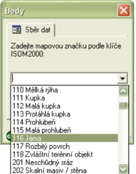
Forms allow us to customize ArcPad for effective collection of data for specific purpose, in our case for orienteering map. The created form provides us choosing map symbol from list of determined values which correspond to a map key. This value is saved in attribute table of new feature. See Chyba! Nenalezen zdroj odkazů..
The forms can be created by ArcPad Application Builder. The form can after be associated with specific shapefile simply by writing it to separate file with the same name and .aplextension. This file can be edited in any text editor. Symbology is defined by XML tags usingArcPad XMLlanguage. Using software ArcPad Application Builderis conditioned by having license key. In the other way the files created in this program can be edited in any text editor. Knowledge of ArcPad XML allows us
working without this commercial software. Forms creation is described in Šilhavý 2007.
Symbology – you can see in the Fig. 2: ArcPad – importance of symbology, the data visualization without symbology is very unsuitable. ArcPad assigns symbology in accordance with the values of feature attribute. Using symbology does not change the geometry of collected data and helps working with this data.
1http://www.esri.com/software/arcgis/arcpad/index.html 2
http://www.ocad.com/en/index.htm
3See e.g.http://www.maprunner.co.uk/content/view/75/183/
Fig. 1:ArcPad – collection data form. Explanation: pictures and screenshots from the first project are in Czech, because the of the project orientation to
There exists several ways to create the symbology. The tool Symbol Property Editor from ArcMap offers graphical symbology editing with prompt preview. Function Get data for ArcPad7 exports the symbology to format used in ArcPad. Easy way to get the symbology is to use ArcPad. In the shapefile properties is Symbology bookmark where simple symbology can be set. The most controlled way to create complex symbology is to useArcPad XML. Symbology creation is described in Šilhavý 2007.
WGS-84 – S-JTSK transformation using projection file. Working in the national spatial coordinate system JTSK in mobile GIS can be found evident for Czech Republic. S-JTSK can be set in ArcPad as coordinate system using projection fileS-JTSK Krovak EastNorth.prj. But it is necessary to know that primary spatial system of collected data by GPS is always WGS-84 and the transformation to the national system (which is realized using the projection file) influences data accuracy. Thus it is important to correctly set the area of interest (AOI). Transformation parameters set for Czech Republic is named S_JTSK_To_WGS_1984_1. This transformation has variance about 1-3 m (Urban 2006) and thus it is acceptable to transform data measured by navigation GPS4.
The background layers preparation. Background data are used for orientation in field. They can be stored in both vector and raster format. E.g. orthophoto map is typically stored as raster; digital elevation model can be stored as vector or raster. ArcPad helps get this data from IMS, WMS or WFS server (for example http://geoportal.cenia.cz). Function Add Internet server finds the server and selected layers can be added to ArcPad. Function Save Map As can save data displayed in the window as a georeferenced raster in PNG format5. To open this raster in software OCAD it must be
converted to JPEG or TIFF format and the extension of associated georeferencing file must be correctly renamed.
2.2 Data collection
This article is not focused on describing of handling with ArcPad in field. But there are shortly expressed some of our experiences with the equipments (from both projects):
• Using indoor PDA is unpractical. There are several limitative factors - low battery persistence,
unfavorable weather conditions like rain or even direct sunshine. Therefore we recommend to use resistant outdoor PDA.
• The final attainable accuracy is influenced by used GPS device. Thus it is appropriate first to
think about the desired accuracy and select appropriate GPS receiver and measurement method.
4
Using more accuracy GPS (GIS or geodetic) requires to use other way to transform data from WGS-84 (resp. ETRS-89) to S-JTSK. It means local key or grid transformation.
5
It is usually not possible to get vectors directly from a map server, because of data protection policies applied by data providers.
Fig. 2:ArcPad – importance of symbology
• An external antenna placed e.g. on head is better than integrated one. Human body covers
significant part of horizon.
Note: The navigational GPS NAVSTAR receiver has been used in both described projects. It is possible to achieve the horizontal accuracy equal to 12 meters6 under optimal conditions. The accuracy can be verified against orthophoto map and also can be controlled during mapping, when relative relationships (such as distance, angle and shape) among mapped objects are being validated. If there appears an aggravation of accuracy (signalized usually by parameter DOP or RMS7depending on receiver type) it is possible to figure it out directly in field using some of above described verification methods. Then it is possible to map the area in different time (under different satellite configuration). Or, if the situation is not time dependent (e.g. it is a problem of signal multipath or interference in the area), it is necessary to use other – usually terrestrial mapping method.
Working with ArcPad in the field is deeply described in Šilhavý 2007. 2.3 The processing of collected data
After coming back to office the data (shapefiles for points, lines and polygons) from mobile device is uploaded to desktop computer. This transfer is made by cable, memory card or Bluetooth. This shapefiles are then modified in desktop ArcPad if necessary. The data in shapefile format is necessary to convert to OCAD format. Standard versionof OCAD does not allow direct import of shapefiles, but the data can be converted by free softwareDXF Authorto DXF format.
This output is then modified by own programmed script in Python language and imported to OCAD. During this import the data is associated with correct symbols using supportive CRT files (Cross Reference Tables). CRT file is text file where in one row is one association condition. See example 1:
OCAD symbol DXF layer
504.0 Road 504 Silnicka
505.0 Vehicle track 505 Vozova cesta
506.0 Footpath 506 Pesi cesta
507.0 Small footpath 507 Pesina
(1)
The Professional version of OCAD supports direct import of shapefile format, so the conversion to DXF is not necessary in this case. But after import the data is again displayed without any symbology. As well as the import to OCAD Standard, the data imported to professional version has to be associated with symbols. The difference is that OCAD Professional uses CNT files (instead of CRT) for symbol conversion.
No matter what version of OCAD is used, attributes collected in the field (using predefined forms) are used to associate features to proper OCAD symbology.
After import and association follows cartographic work like control and map composition. That is typical map production tasks in OCAD.
3
Support of geomorphologic research in field – the mobile part of GmIS
This chapter describes key parts of the realized GIS – GIS solution. The solution is based on ArcPad as a mobile client and ArcGIS8 as a desktop application on server side. It has been created for purposes of Geomorphologic information system (GmIS)9.6
And 1.5 – 2.5 times worse vertical accuracy.
7DOP – dilution of precision, RMS – root mean square error 8
http://www.esri.com/software/arcgis/index.html 9http://git.zcu.cz/wiki/index.php/GmIS
The aim of this solution is to help a geomorphologist to properly record and consequently interpret his/her field survey. The geomorphologist has a geomorphologic database consisting of a lot of layers (see more in Minár et. al 2005 and Mentlík et. al 2006), but two of them are important for further explanation. Layer of elementary forms10 is used as a background in field survey. Collected data is stored in layer (or set of layers) of documentation materials during the survey. These data are after transported to server application and there interpreted using developed tools. The solution is also described at pages focused on GmIS11.
Either of described projects has different thematic focus, but the technology of both of them is particularly the same. There are highlighted just technologic differences against the GIS – CAD solution in following GIS – GIS solution description.
3.1 The data preparation in office
In this case all necessary data for project is prepared completely in ArcGIS software. ArcMap toolbar ArcPad and tool Get Data for ArcPad7 are determined to data preparation for ArcPad. This tool provides transferring background layers from shapefile or geodatabase, features symbology and projection file from ArcMap to ArcPad. The forms for ArcPad are made on the same way like in previous project.
3.2 Data collection
Data collection is technologically similar to previous project, only its thematic content is different. More information is written in Jedlička 2008.
3.3 The processing of collected data
To import the collected data and apply changes to database is used ArcMap toolbarArcPadespecially the toolCheck In Edits From ArcPad. The main handling with data is coming after import.
The purpose of tools developed for this project is to help with editing attributes of ElementaryForms
10
Elementary form(of georelief) is (at particular level of detail) geometrically homogeneous face with uniform genesis and assumption for homologous run of recent geomorphologic processes (dynamics of development). Therefore, elementary form boundaries mark breaks in geometric, genetic and dynamic homogeneity. Thus it is possible to say that elementary form is, at particular level of detail, naturally bounded fundamental segment of georelief. Adapted from Minár 1996.
11http://git.zcu.cz/wiki/index.php/GmIS_GmT_GUIForEditingElementaryForms
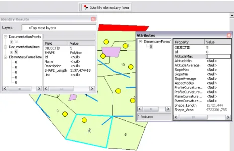
layer in office. The information fromDocumentation materialslayers (filled in field) combined with other types of (geomorphologic) information determines attributes of each elementary form. The expert – geomorphologist is necessary to interpret that information but the developed interactive tool can make his/her work easier. GmIS provides a tool that helps to edit ElementaryForms layer (see Fig. 3: Screenshot from tool). After selection of specific elementary form the tool Editing elementary form attributes displays information about features from Documentation materials layers inside selected elementary form and about nearby features from ElementaryFormslayer. This information is can be useful for determination of attributes of the specific elementary form.
To programming this useful tool the open application interface of software ArcGIS was used. The program was written using ArcObjects and Visual Basic for Application.
4
Summary and compare
The paper describes two projects, realized at University of West Bohemia in Pilsen, department of mathematics, geomatic section. Experiences from these projects and some recommendations whose can be found helpful by other people dealing with the mobile GIS follows:
The data preparation in office
• It is necessary to choose proper and precise enough transformation of coordinate systems
between WGS-84 and national coordinate system.
• Customization of mobile GIS environment can significantly speed up the work in field (e.g.
forms for ArcPad).
• The preparation of background layers: In the GIS – CAD solution it requires extra work,
whereas in the GIS – GIS solution there exists built in export tools
• The same situation is about symbology creation. In the case GIS – CAD the symbology is
written toaplfile using ArcXML or extra created inArcPad Application Builderand in the case GIS – GIS the symbology for ArcPad is automatically derived from ArcMap.
• The GIS – GIS solution has an additional benefit to GIS – CAD. It is the raster format MrSID
which is used to save disk space on mobile device. The GIS – CAD solution works with TIFF or JPEG formats that have both lower compression rates.
Data collection
• The collection of data is technologically equivalent to both projects. Some experiences were
noticed here. Indoor PDA was found unsuitable and outdoor PDA was recommended. The processing of collected data
• The data processing requires more than copy data from mobile device to desktop computer
and more than import data to software. The data must be changed to final result of the project. Each project has own way to achieve that.
• In the GIS – CAD solution the data is necessary to convert different file format. Supportive
files CRT or CNT must be created to preserve the symbology. In the GIS – GIS solution is no necessity to do a data conversion. Data is kept in the shapefile format and imported to geodatabase and the conversion is encapsulated.
• During the import after field survey in GIS – GIS case, just changed data are uploaded.
Incidental collisions can be solved using conflict manager.
On the other hand the GIS – CAD solution imports all collected data. That means the data must be mapped in not overlapping areas.
• For further processing ArcGIS offers open application interface to make own tools and scripts.
Reference
1. ESRI. 2008a. ESRI Developer Network - Documentation for developers using ArcGIS 9.2. On-line <http://edndoc.esri.com/arcobjects/9.2/welcome.htm>.
2. JEDLIČKA, K. 2008. Geomorphologic information system - use cases.In Sborník symposia GIS Ostrava 2008. Ostrava.Tanger, 2008. s. 1-9. ISBN 978-80-254-1340-1. On-line
<http://gis.vsb.cz/GIS_Ostrava/GIS_Ova_2008/sbornik/index.htm>.
3. MENTLÍK, P., JEDLIČKA, K., MINÁR, J., BARKA, I. 2006. Geomorphological information system:
physical model and options of geomorphological analysis.In Geografie. year 111, no 1., pages 15-32.
4. MINÁR, J. 1996. Niektoré teoreticko-metodologické problémy geomorfológie vo väzbe na tvorbu komplexných geomorfologických máp.Acta Facultatis Rerum Naturalium Univesitatis
Comenianae, Geographica Nr. 36, 7–125.
5. MINÁR, J., MENTLÍK, P., JEDLIČKA, K.; BARKA, I. 2005. Geomorphological information system: idea and options for practical implementation.In Geografickýčasopis.Year 57, no 3, pages 247-266,
ISSN 0016-7193.
6. RAPANT, P. 2006. Geoinformatika a geoinformační technologie. Ostrava. VŠB - Technická
univerzita Ostrava, Hornicko-geologická fakulta, Institut geoinformatiky, 2006., 463 s. ISBN: 80-248-1264-9.
7. URBAN2006.ArcPad 7 a S-JTSK. In. ArcRevue n. 2. 2006. On-line: <http://www.arcdata.cz/digitalAssets/38106_ArcRevue2-06.pdf>.
8. ŠILHAVÝ, J. 2007Využití moderních metod pro tvorbu map pro orientační běh. Plzeň. Západočeská univerzita, Fakulta aplikovaných věd, 2007. -- 39 s. On-line
<http://gis.zcu.cz/studium/ZaverecnePrace/2007/Silhavy__Vyuziti_modernich_metod_pro_tvorbu_ map_pro_orientacni_beh__BP.pdf>.