C 16 MANUFACTURING ENGINEERING: Materials Science JOURNAL OF ENGINEERING SCIENCES
ЖУРНАЛ ІНЖЕНЕРНИХ НАУК
ЖУРНАЛ ИНЖЕНЕРНЫХ НАУК
Web site: http://jes.sumdu.edu.ua DOI: 10.21272/jes.2019.6(1).c4 Volume 6, Issue 1 (2019)
UDC 621.791.927.5
Study of a Welding Pool Harmonic Oscillations Influence
on the Welded Metal Hardness and Weld Bead Width
Lebedev V. A., Solomiichuk T. G., Novykov S. V.*
E. O. Paton Electric Welding Institute of the National Academy of Sciences of Ukraine, 11 Kazymyra Malevycha St., 03150 Kyiv, Ukraine
Article info: Paper received:
The final version of the paper received: Paper accepted online:
December 20, 2018 February 8, 2019 February 13, 2019
*
Corresponding Author’s Address:
[email protected]
Abstract. The comparison results of the hardness measuring of welded metal and the heat-affected zone of the eight welded beads from low-carbon steel obtained by surfacing CO2/MAG with welding bath oscillation influence at values of amplitude equaled 0.5 mm (frequency values were 2.5, 3.0, 4.0, and 4.5 Hz) and 4.0 mm (frequency values were 3.7, 3.8, 3.9, and 4.0 Hz) are presented. A technological mode was the same for all specimens. The special in-fluence of amplitude on the hardness value is noted. The structural metal components of the beads with a maximum hardness value are presented. An analytical calculation of the beads width depending on the value amplitude equaled 6 mm and oscillation frequency (values equal 2.5, 3.0, 4.0, and 4.5 Hz) of the weld pool is presented. A comparative analysis of the calculated and experimental values of the beads width is given. The influence of the oscillation fre-quency on the width value is noted.
Keywords: surfacing, oscillations, amplitude, frequency, acicular ferrite, hardness.
1
Introduction
One of the ways to increase the technological strength of welded structures is to control for the crystallization of the weld pool. A control tool is a welding torch or a melt of a weld pool on which a periodic influence in the form of vibrations or vibrations is superimposed. Crystalliza-tion of the weld pool metal in such condiCrystalliza-tions contributes to the formation of a fine-grained structure of the weld metal and directional crystal growth it is reasons to ob-taining high mechanical properties [1–3].
The method of imposing oscillations (vibrations) can be mechanical, i. e. when the weld pool [1–6, 8–10] or the welding tool [2, 7] oscillates during the process of welding or surfacing; the use of modulated welding cur-rent (pulsed curcur-rent) [11]; periodic influence of an exter-nal magnetic field [12], which in a certain way influences the melt of the weld pool, the welding arc [13] or the laser beam [14].
However, the simplest and cheapest way to control the structure of the crystallizing metal of the weld pool, which does not require expensive and complex equip-ment, is the mechanical method of superimposing exter-nal oscillations.
2
Literature Review
Nowadays, welding technologies with different types of mechanical periodic influences on the crystallization of a weld pool melt exist and have being investigated. So, the use of transverse mechanical vibrations of the weld pool makes it possible to increase the hardness of the weld metal by 2.5 % at a frequency of 60 Hz and by 7.3 % at a frequency of 376 Hz [4] on stainless steel spec-imens.
The apply of longitudinal oscillations of the weld pool with a frequency of 400 Hz and an amplitude of 40 μm provides the formation of a weld when welding medium-carbon steel with significantly improved mechanical properties: the yield strength is increased by 21 %, the ultimate tensile strength is 26 %, and breaking strength – by 39 % compared with specimens were obtained without the influence of oscillations [5].
Journal of Engineering Sciences, Volume 6, Issue 1 (2019), pp. C 16–C 21 C 17 mode of welding, it is possible to carry out multi-pass
automatic welding without the use of a backing plate of the seam already at a frequency of 2.5 Hz. Herewith, the depth is higher than at a frequency of 5 Hz [7].
The apply of vibrations of the weld pool in welding of aluminum alloy AA7075 has significantly improved the resistance to hot cracking. So, with a frequency of 2050 Hz reported to the weld pool, it was possible to reduce the sensitivity to hot cracking to 20 %, while in the with-out of vibrations this value reached 82 %. However, the apply of vibrations frequency of the order of 100 Hz does not only not makes reduce the sensitivity of hot cracking, but increases it to 87 % [8].
The authors of work [9] executed welding of speci-mens from mild steel with a vibrator immersed in the weld pool and which transmitted vibrations from the ERM motor to the weld pool with a maximum frequency of 300 Hz and an amplitude of 0.5 mm. specimens weld-ed at this frequency had an increasweld-ed micro hardness due to the favorable orientation of the crystals and their re-finement. At the same time, yield strength increased by 27 %, and ultimate tensile strength – by 23 % compared with samples welded without the influence of vibration.
A key feature of manual welding technology of the low carbon and stainless steels specimens with vibrations applying described in [10] is the use of vibrating engrav-ers, where the welder’s hand with a welding torch is placed. The vibration frequency in the experiments was 600 Hz, 800 Hz, and 1 kHz, and the amplitudes were 0.235, 0.324, and 0.425 mm, respectively. It was noted that due to dendrites refinement, it was possible to maxi-mally (at 1 kHz) increase the impact strength of welded specimens by 25 %.
From the above examples it follows that the use of pe-riodic mechanical action during the welding process forms crystals during the period of crystallization by refinement and accelerates their growth, it most favorably takes influence the mechanical properties such as hard-ness, yield strength, impact strength and especially tensile strength (an increase of 39 % [5]) and sensitivity to hot cracking (decrease to 20 % [8]).
The aim of this work is to study the effluence of the amplitude - frequency characteristics of the weld pool low - frequency mechanical oscillations on the weld met-al hardness and the weld beads width. A key feature of the research is the type of transverse oscillations. They are reciprocating motion along a circle arc, as shown in Figure 1. The deviation angle from the vertical position does not exceed 20°.
3
Research Methodology
3.1
Experiments
Experiments are semiautomatic CO2\MAG surfacing. As electrode is a steel wire enveloped into the copper of type ER70S-6 (C: 0.06-0.15 %; Si: 0.80–1.15 %; Mn: 1.40–1.85 %; P: 0.025 %; S: 0.035 %) with a diame-ter of 1.2 mm is fed by a welding semiautomatic feed device (SFD) through the welding torch into arc burning zone.
The surfacing current is controlled by the electrode wire feed speed. The wire feed speed is carried out both smoothly and discreetly through the corresponding toggle switches on the control panel. The surfacing current value was determined by an ammeter located on the front of the power source. The power source is a rectifier for manual and automatic welding, providing a maximum current of up to 400 A.
A welding torch mechanical rectilinear motion is car-ried out through a movable frame with a smooth control tumbler of motion speed.
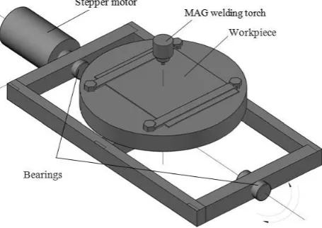
A specimen is fixed on a welding frame oscillating along a circle arc in the direction perpendicular to the surfacing direction. The welding frame oscillations are generated by a stepper motor. The amplitude and fre-quency of oscillations are set directly through the stepper motor control panel Figure 2. The maximum frequency at which the stepper motor is a stable mode work is 4.5 Hz. The amplitude of the surfacing bead stable formation is does not exceed 6–7 mm. The welding frame was set in oscillatory motion state after 5–7 seconds from the mo-ment ignition of welding arc.
Figure 1 – The welding frame scheme of transverse vibrations of the weld pool
C 18 MANUFACTURING ENGINEERING: Materials Science Nine plates with size 180×40 mm of low-carbon steel
thickness 8 mm were used as specimens for surfacing. Before surfacing, each specimen was cleared of protec-tive coating, rust and oils by means of mechanical grind-ing.
As gas used in the experiments was technical CO2 – 99.5 %. Technological modes of surfacing were: I = 215 А, U = 26 V; V = 36 m/h; gas flow rate in a range of 9–12 l/min; amplitude-frequency responses of the welding frame oscillations are presented in Table 1. Table 1 – The values of amplitude-frequency characteristics at which specimens were obtained
Specimen no. Frequency, Hz Amplitude, mm 1 Without oscillations
2 2.5
0.5
3 3.0
4 4.0
5 4.5
6 3.7
4.0
7 3.8
8 3.9
9 4.0
3.2
Hardness measurement
For hardness measure all specimens were cut trans-versely and then all weld bead cross sections were pol-ished to purity level of 14. Then there were etched about chemically in a 4 % alcoholic solution of nitric acid for 10 seconds.
The study of the welded metal structure and heat-affected zone (HAZ) metal structure, as well as photo-graphing the structures obtained were carried out on a microscope “NEOPHOT-32” and using the “OLYMPUS” digital camera.
Vickers hardness at a load of 100 g (microhardness) was measured in the center of casted crystallites. The values of the welded beads hardness are presented in Table 2.
3.3
The calculation of welded bead width
by the amplitude-frequency response
It is known, in surfacing it is necessary to achieve the minimum penetration depth of the base metal and to ob-tain a weld bead with a maximum width and minimum gain. However, to increase the width, it is necessary to increase the input of heat into the base metal, that also increases the depth of penetration [16, 17]. Using trans-verse oscillations, it is possible to reduce the penetration depth and significantly increase the weld bead width without arc current and voltage increase.
When surfacing a workpiece that performs harmonic oscillations by a given law, the width of the weld bead H is described by the equation of harmonic oscillator forced oscillations:
, 2 cos
2 2 0
0 2 2 t m F x dt dx dt x
d
(1)
Where x – current coordinate of the weld pool melt mass center, m; 2 /( h2)
рм
– coefficient of viscous friction;
0
(
g
/
l
)
1/2 – eigenfrequency of freeoscilla-tions of melt; β – viscosity coefficient of melt metal, Pa∙s; m – mass of the welding frame on which the specimen is fixed, kg; h – distance from the melt mass center to the interfacial border, m; ρls – density of liquid steel, g/cm3;
g – acceleration of gravity, m/s2; l – distance from the axis of oscillation to the melt mass center, m; F0 – driving force amplitude, N; ν – the external oscillation frequency that is given, Hz.
A solution of equation (1) will have the form [18]:
2 2
2 4 2 2cos
2
,0
0
t m F t x (2)
where arctg[2/(022)] – shear angle between driving force F0cost and x(t) coordinate. The driving force F0 is related to the torque on the shaft of the step-ping motor M0, N∙m by the expression: F0M0/l. The moment magnitude M0 is determined by the oscillation amplitude and the welding frame mass of the frame with the workpiece fixed on it by the expression: M0Amg, where A is oscillations amplitude.
The weld pool melt within of the heat saturation period t has the sphere shape of a volume V, one can approxi-mately determine the distance from the melt mass center to the interfacial border h as the sphere radius:
. 4 3 4 3 3 3 ls m V h (3)
The metal mass of the weld pool m [kg] without taking into account the losses for spraying and evaporation tak-ing into account (2), can be determined by the expression [19, 20]:
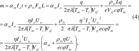
, 2 2 2 2 2 2 2 2 m a ls m sf i m a a m sf i m a a ls sf i m a a a m m sf ls sf i m a m m ls a m T ec U V T T U I T ec V T T U I V T T U I I T с eV Lq V T T q I L F t I m (4)where mIat - the mass of weld pool metal because of the electrode melting. Where αm = 15–25 g/(А∙h),
when surfacing /welding in СО2 – the melting coefficient; L
Fm ls
– mass of weld pool metal because of the base metal melting; Fm – melting cross-sectional area of the
base metal, m3; L – weld pool length, m; сφ – volumetric heat capacity, J/(m3·K); qIaUa – effective power of welding arc, W; η – efficiency of arc heating; Ia – arc
current, A; Ua – arc voltage, V; λ – coefficient of thermal
conductivity, W/(m∙K); Тm – metal melting
tempera-ture, K; Тi – initial metal temperature, K; Vsf – surfacing
Journal of Engineering Sciences, Volume 6, Issue 1 (2019), pp. C 16–C 21 C 19
4
Results
4.1
The influence of amplitude-frequency
response on the value of hardness
As a result, the Vickers hardness values of welded beads are presented in Table 2.
The study of the welded metal beads microstructure of all nine specimens showed the classical orientation of the crystallites - the crystals grow perpendicular to the sec-tion plane of the metal bath and the base metal. Besides,
in all specimens the crystallites become larger, as the distance from the fusion zone increases [15].
In all surfacing variants the structure is same approxi-mately and consists of various modifications ferrite (po-lygonal, polyhedral, acicular) and perlite (Figure 3).
Polygonal ferrite is observed in the form thin lengthen extractions along of casted crystallites boundaries. Poly-hedral ferrite is clusters in the equiaxial ferritic grains form. Acicular ferrite is observed in the bodies of casted crystallites in the form of basket weaving plates. Perlite is observed in the form of dispersed extractions along the ferritic grains boundaries.
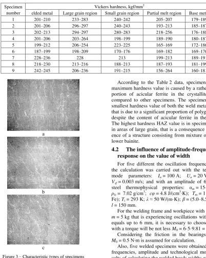
Table 2 – The Vickers hardness values of welded beads
Specimen number
Vickers hardness, kgf/mm2
elded metal Large grain region Small grain region Partial melt region Base metal 1 201–210 233–283 240–242 205–207 179–189 2 201–206 296–297 240–243 193–213 185–187 3 202–213 294–297 280–283 218–256 176–188 4 201–206 203–264 198–199 189–190 180–187 5 199–212 206–254 223–225 165–169 172–186 6 187–199 198–209 170–176 169–182 169–176
7 228–236 228 213 199–213 189–191
8 218–230 213–216 188–213 187–193 181–199 9 242–245 206–236 191–215 156–264 160–181
a
b
c
Figure 3 – Characteristic types of specimens microstructures ×200: a – cross section center of welded bead;
b – fusion line; c – root part
According to the Table 2 data, specimens 9 has the maximum hardness value is caused by a rather large pro-portion of acicular ferrite in the crystallites structure compared to other specimens. The specimen 6 has the smallest hardness value of both the weld metal and HAZ, that is due to a significant proportion of polygonal ferrite, despite the content of acicular ferrite in the crystallite. The highest hardness HAZ value is in specimens 2 and 3 in areas of large grain, that is a consequence of the pres-ence of a structure consisting from mixture of upper and lower bainite.
4.2
The influence of amplitude-frequency
response on the value of width
For five different the oscillation frequency values ν, the calculation was carried out with the technological mode parameters: Ia = 100 А; Ua = 20 V; η = 0.8;
Vsf = 0.003 m/s; and with an amplitude of 6 mm, black
steel thermophysical properties: αm = 15–25 g/(А∙h);
ρls = 7.02 g/сm3; сφ = 4.8 J/(сm3∙K); Tm = 1 810 K (for
Fe); Ti = 293 K; λ ≈ 50 W/(m·K); β = (5.0–8.5)·10–3 Pа∙s;
l = 150 mm.
For the welding frame and workpiece with total weight m = 5 kg that is experiencing oscillations with amplitude equals up to 6 mm, it is necessary to choose an engine with a torque will be not less M0 = 6·5·9.81 = 0.3 (N·m).
Considering the friction in the bearings, the value M0 = 0.5 N∙m is assumed for calculation.
C 20 MANUFACTURING ENGINEERING: Materials Science
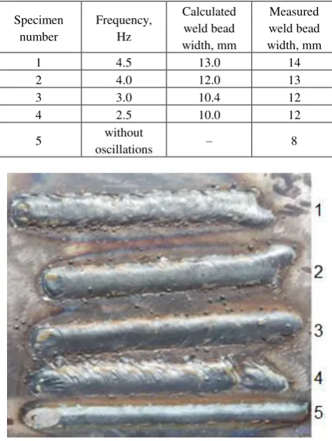
Table 3 – The calculated and measured width values of the weld beads
Specimen number
Frequency, Hz
Calculated weld bead width, mm
Measured weld bead width, mm
1 4.5 13.0 14
2 4.0 12.0 13
3 3.0 10.4 12
4 2.5 10.0 12
5 without
oscillations – 8
Figure 4 – Weld beads for the different frequencies: 1 – 4.5 Hz; 2 – 4.0 Hz; 3 – 3.0 Hz, and 4 – 2.5 Hz; 5 – without
oscillations
5
Conclusions
These studies demonstrate a tendency to increase the weld bead metal hardness and HAZ with increasing fre-quency and especially the amplitude of external oscilla-tions. Consequently, if at amplitude value of 0.5 mm and an oscillations frequency of 4.5 Hz, the hardness of a welded bead metal did not almost change in comparison with a welded bead metal of bead obtained without weld pool oscillations, then at an amplitude of 4 mm, the hard-ness increased 1.16 times. The reason for this effect is to increase the degree of fine-grained metal confirmed by the results of the work [3], obtained under conditions close to that experiments. In addition, this effect is due to a significant increase in the proportion of acicular ferrite in the weld bead metal compared to the amount of poly-hedral and polygonal ferrite, which confirms the hypothe-sis outlined in the work [21] according to it by means of a weld pool mechanical oscillations can change not only the grain size, but also to form useful structural compo-nents of the welded metal without introducing additional alloying.
This analytical calculation allows us to estimate the weld bead width with an accuracy of 7–20 %. Moreover, the lower the frequency, the higher a magnitude of the error. This is probably due to a features of a welding arc burning, a degree of burning stability of which somewhat decreases at a lower frequency due to re-ignition after a short circuit. This feature requires further study and is not taken into account in this calculation. Also, these studies have shown that the frequency is not only a factor in con-trolling the metal microstructure of the weld bead, but also controlling its width, which is confirmed by the re-sults of the work [22].
References
1. Kuo, C.-W., Yang, S.-M., Chen, J.-H., Lai, G.-H., Chen, Y.-C., Chang, Y.-T., & Wu, W. (2008). Preferred Orientation of In-conel 690 after Vibration Arc Oscillation Welding. Materials Transactions, Vol. 49(3), pp. 688–690, doi: 10.2320/matertrans. mep2007305.
2. Jose, M. J., Kumar, S. S., & Sharma, A. (2016). Vibration assisted welding processes and their influence on quality of welds.
Science and Technology of Welding & Joining, Vol. 21(4), doi: 10.1179/1362171815y.0000000088. 3. Selvi, A. A. (2014). Effect of linear direction oscillation on grain refinement. Ohio State University.
4. Hsieh, C.-C., Wang, P.-S., Wang, J.-S., & Wu, W. (2014). Evolution of microstructure and residual stress under various vibra-tion modes in 304 stainless steel welds. The Scientific World Journal, Vol. 2014, pp. 1–9, doi: 10.1155/2014/895790.
5. Tewari, S. P. (2009). Influence of Longitudinal Oscillation on Tensile Properties of Medium Carbon Steel Welds of Different Thickness. Thammasat International Journal of Science and Technology, Vol. 14(4), pp. 17–27.
6. Gill, J. S., Kalyan, R. T. (2018). Effect of Weld Pool Vibration on Fatigue Strength and Tensile Strength of Stainless Steel Butt Welded Joints by GTAW Process. Proceedings of the World Congress on Engineering, Vol. 2.
7. Yamane, S., Yoshida, T., Nakajima, T., Yamamoto, H., & Oshima, K. (2009). In process control of weld pool using weaving control in switch back welding. Quarterly Journal of the Japan Welding Society, Vol. 27(2), рp. 32s–36s, doi: 10.2207/ qjjws.27.32s.
8. Balasubramanian, K. (2011). Studies on the effect of vibration on hot cracking and grain size in AA7075 aluminum alloy weld-ing. International Journal of Engineering Science and Technology, Vol. 3(1), pp. 681–686.
9. Singh, P. K., Patel, D., & Prasad, S. B. (2016). Development of vibratory welding technique and tensile properties investigation of shielded metal arc welded joints. Indian Journal of Science and Technology, Vol. 9(35), pp. 1–6, doi: 10.17485/ijst/2016/ v9i35/92846.
Journal of Engineering Sciences, Volume 6, Issue 1 (2019), pp. C 16–C 21 C 21
11. Subravel, V., Padmanaban, G., & Balasubramanian, V. (2017). Optimizing the magnetic arc oscillation process parameters to at-tain maximum tensile strength using RSM. Journal of Manufacturing Engineering, Vol. 12(1), pp. 49–54.
12. Razmyshlyaev, A. D., Ahieieva, M. V., & Lavrova, E. V. (2018). TMF Influence on Weld Structure at the Welding of 12Cr18N9T. Materials Science Forum, Vol. 927, pp. 1–5, doi: 10.4028/www.scientific.net/msf.927.1.
13. Sundaresan, S., & Ram, G. D. J. (1999). Use of magnetic arc oscillation for grain refinement of gas tungsten arc welds in α-β ti-tanium alloys. Science and Technology of Welding and Joining, Vol. 4(3), pp. 151–160, doi: 10.1179/136217199101537699. 14. Schmitt, F., Mehlmann, B., Gedicke, J., Olowinsky, A., Gillner, A., & Poprawe, R. (2010). Laser beam micro welding with high
brilliant fiber lasers. Journal of Laser Micro/Nanoengineering, Vol. 5(3), pp. 197–203, doi: 10.2961/jlmn.2010.03.0003. 15. Rabin, V. F., & Denisenko, A.V. (1978). Metal science of low- and medium-alloyed steels welding. Naukova Dumka, Kyiv. 16. Mondal, A., Kumar Saha, M., Hazra, R., & Das, S. (2016). Influence of heat input on weld bead geometry using duplex stainless
steel wire electrode on low alloy steel specimens. Cogent Engineering, Vol. 3(1), pp. 14, doi: 10.1080/23311916.2016.1143598. 17. Gautam, U., & Abbas, M. (2013). Analysis of weld bead geometry in saw and modeling using CCD. International Journal of
Mechanical Engineering and Robotics Research, Vol. 2(3), pp. 168–181.
18. Trubetskov, D. I., & Rozhnev, A. G. (2001). Linear oscillations and waves. Fizmatlit, Moscow.
19. Volchenko, V. N., Yampolsky, V. M., Vinokurov, V. A., etc. (1988). Theory of welding processes. Vyschaya Schkola, Moscow. 20. Rykalin, N. N. (1951). Calculations of thermal processes in welding. Mashgiz, Moscow.
21. Lebedev, V. A., Yarovitsyn, О. V., & Novykov, S.V. (2016). Methods of acicular ferrite forming in the weld bead metal (Brief analysis). Reporter of the Priazovskyi State Technical University. Section: Technical Sciences, Vol. 32(1), pp. 113–117. 22. Xu, W., Lin, S., Yang, C., & Fan, C. (2015). Weld bead formation in oscillating arc narrow gap vertical-up GMAW process.
Transactions of the China Welding Institution, Vol. 36(4), pp. 56–60.
Вивчення впливу гармонічних коливань
зварювальної ванни на твердість
зварювального металу і ширину зварного шва
Лебедєв В. А., Соломійчук Т. Г., Новиков С. В.
Інститутелектрозварювання ім. Є. О. Патона НАН України, вул. К. Малевича, 11, 03150, м. Київ, Україна
Анотація. У роботі наведено результати порівняння твердості зварюваного металу і зони теплового
впливу восьми зварних швів з низьковуглецевої сталі, отриманої наплавленням CO2/MAG за впливу коливань
на зварювальнуванну при значеннях амплітуд 0,5 мм (для частот 2,5, 3,0, 4,0 і 4,5 Гц) та 4.0 мм (для частот 3,7, 3,8, 3,9 і 4.0 Гц). При цьому технологічний режим був однаковим для всіх зразків. У результаті
відзначено особливий вплив амплітуди на значення твердості. Також наведені структурні металеві
компоненти швів з максимальним значенням твердості. Запропоновано методику аналітичного розрахунку
ширини шва в залежності від амплітуди (дорівнює 6 мм) і частоти коливань (значення 2,5, 3,0, 4,0 і 4.5 Гц)
зварювальної ванни. Наведено порівняльний аналіз розрахункових та експериментальних значень ширини
шва. Відзначено вплив частоти коливань зварювальної ванни на ширину зварного шва.