Throughput Analysis in an Infrastructure-based Mesh
Network using BeeHive Algorithm
Kiran K.
University Visvesvaraya College of Engineering Bangalore, India
Vaishnavi K.
Viterbi School of Engineering University of Southern CaliforniaLos Angeles, CA, USA
P. Deepa Shenoy
University Visvesvaraya College of Engineering Bangalore, India
Venugopal K. R.
University Visvesvaraya College of Engineering Bangalore, India
ABSTRACT
WiMAX and WiFi are among the major wireless technologies esca-lating today. Both these technologies provide last mile connectivity and differ in their Media Access Control (MAC) layer and physical (PHY) layers. Since most of the devices are equipped with WiFi, and WiMAX is prevailing in today’s devices, an efficient way of routing the data is by making use of both these technologies si-multaneously. This work presents such a technique based on the Bee-hive routing algorithm for an infrastructure-based mesh net-work, which promotes interoperability between the WiMAX and WiFi technologies. The network consists of two types of nodes -1)coordinator node 2)subscriber node, and divides the entire net-work into regions called foraging regions/zones based on the hop count from the coordinator node. A detailed implementation of this algorithm is presented in this work. The algorithm is tested for var-ious mobile and static topologies by varying the parameters such as the speed of motion of the mobile nodes and the hop limit.
General Terms:
Long Routing Table, Short Routing Table
Keywords
Coordinator Node, Foraging Region, Subscriber Node, WiFi, WiMAX
1. INTRODUCTION
WiMAX (Wireless Interoperability for Microwave Access) is a wireless point-to-multipoint (PMP) standard approved by IEEE 802.16, which defines both the Medium Access Control (MAC) and the physical (PHY) layers. It is a MAN standard providing last mile connectivity. It provides a data rate of upto 376 Mbps[1] and covers a range of 10 Kms to 50 Kms[2]. It operates in the 10 to 66 GHz licensed and unlicensed band[2]. A WiMAX base sta-tion can support more than 500 subscriber stasta-tions[3].
WiFi (Wireless Fidelity) is a wireless LAN standard based on IEEE 802.11. It provides a data rate of upto 6.933 Gbps[4] and covers a range of upto 1kms[5]. It operates in the 2.44 to 5 GHz unlicensed band[2]. A WiFi router was designed to handle upto 10 subscriber stations at a given instance of time[3]. However, today’s WiFi routers can handle a larger number of devices. An infrastructure-based network is a centralized network con-sisting of base stations or coordinator nodes and subscriber sta-tions. The overall network is divided into smaller regions with each region consisting of one coordinator node. A message des-tined for any node within the region is sent to the coordinator node which then forwards it to the destination node. Hence, all communications happen through the coordinator node. In this work, communication across the regions happens through this
mechanism. A mesh network consists of peer nodes functioning in a decentralized fashion. The messages are routed directly to the destination node without any centralized control. This is the mode of communication used for nodes within a region in this work.
In this work, an algorithm based on the bee-hive routing proto-col is presented for a heterogeneous infrastructure-based mesh network consisting of two kinds of nodes - coordinator node and subscriber node. The bee-hive algorithm divides the en-tire network into regions called foraging regions or foraging zones. In this work, it is assumed that the coordinator nodes are equipped with both WiMAX and WiFi radios whereas the sub-scriber node’s minimum requirement is a WiFi radio. Routing within the region happens directly in a decentralized mesh mode using the WiFi radio. Inter-foraging zone routing is done through the coordinator node using WiMAX.
The simulations are performed using the OPNET Modeller, a user-friendly network simulator[6].
2. RELATED WORK
3. PROBLEM STATEMENT
This section discusses the problem to be addressed. The prime objective of this work is to introduce interoperability between WiMAX and WiFi technologies in a multi-radio infrastructure-based mesh environment, and analyze the performance for both static as well as mobile topologies. Inorder to achieve this, a tech-nique based on the Bee-hive algorithm is used. An in-depth anal-ysis of the algorithm is made by varying the parameter based on which the regions are formed and the speed at which the mobile nodes move.
4. DESIGN
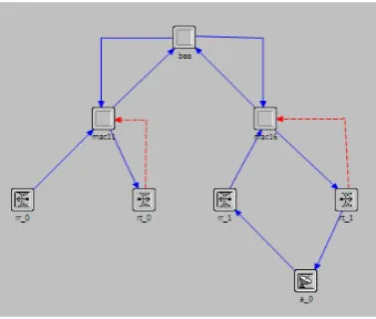
The network considered in this work consists of two types of nodes - coordinator node and subscriber node. The coordinator node is equipped with both WiMAX and WiFi radios. The node model of the coordinator node is as shown in Figure 1.
Fig. 1. Node Model of the Coordinator Node
The layers constituting the coordinator node are as follows:
—beeLayer: It corresponds to the Network layer of the protocol stack and handles the routing pronouncement.
—mac11Layer: This represents the Media Access Control layer in the Data Link layer of the protocol stack. It imple-ments IEEE 802.11, thus represents the WiFi radio of the co-ordinator node.
—mac16Layer: It also corresponds to the Media Access Con-trol layer in the Data Link layer of the protocol stack but im-plements IEEE 802.16, thus representing the WiMAX radio of the coordinator node.
—Carrier Sense Multiple Access with Collision Avoidance (CSMA/CA) algorithm is implemented by both the MAC lay-ers. Not much emphasis is given to the details of its imple-mentation in this work.
—rr1,rt1,rr0andrt0: These are the radio receivers and radio
transmitters corresponding to the WiMAX and WiFi radios re-spectively.
—a0: It is the antenna for the WiMAX radio.
The subscriber nodes whose node model is as shown in Figure 2 have only the WiFi radio.
Its node model has the following layers:
—src Layer: It is analogous to the Application layer of the OSI network architecture, generating data packets required for test-ing the effectiveness of the protocol durtest-ing the simulation. An inbuilt OPNET process model is made use of for this purpose and the data packets generated do not have any destination ad-dress attached to them.
Fig. 2. Node Model of the Subscriber Node
Table 1. Long Routing Table Coordinator
Node ID
Next Hop Coordinator Node
Hop Count List of all subscriber nodes in this region
—trans Layer: It corresponds to the Transport layer of the pro-tocol stack.
—bee Layer: It takes care of the routing decisions to be made. —macLayer: This is the Media Access Control layer of the
subscriber node and is implemented using Carrier Sense Mul-tiple Access with Collision Avoidance (CSMA/CA). It em-ploys the IEEE 802.11 and represents the WiFi radio. —rr0andrt0: Radio receiver and radio transmitter of the WiFi
radio respectively.
4.1 Routing Tables
The coordinator node maintains two types of routing tables:
—long routing table:
This table maintains the information about the nodes outside its foraging region. It contains the list of other coordinator nodes and subscriber nodes that reside in them. The structure of this table is as shown in Table 1.
TheCoordinator N ode ID field represents the coordina-tor node of the destination node’s foraging region. TheN ext Hop Coordinator N odeentry contains the neighbouring co-ordinator through which the packet must pass to reach the des-tination given byCoordinator N ode ID. TheHop Count notifies the number of WiMAX hops from this coordinator to the destination coordinator via the next hop neighbor spec-ified. All the routing actions performed by referring to this table are through the WiMAX radio.
Table 2. Short Routing Table Subscriber
Node
Next Hop Hop Count
Table 3. Routing Table Node Next Hop Hop Count
TheSubscriber N odefield gives the node IDs of the sub-scriber nodes in this foraging region. TheN ext Hopgives the immediate neighbour to the destination inSubscriber N ode and Hop Countgives the number of hops from this node to the destination through this neighbour. All routing actions specified in this table are performed using the WiFi radio.
Each subscriber node maintains a routing table containing infor-mation about nodes in its foraging region. The structure of the subscriber node’s routing table is as shown in table 3.
This table is similar to the coordinator node’s short routing table and theN odefield is the same as theSubscriber N odein the coordinator node’s short routing table.
4.2 Foraging Regions
The entire network is divided into regions called foraging re-gions or foraging zones. All nodes that are withinnhops from the coordinator node belong to one foraging region. Initially, the coordinator node broadcasts aregisterpacket through its WiFi radio. When the subscriber nodes which do not belong to a region receive this packet, they update their region to that of this coor-dinator and acknowledge the coorcoor-dinator. Upon receiving this acknowledgment, the coordinator node adds the subscriber node to its short routing table.
4.2.1 Static Network. In the case of a static network, since the nodes are static, the foraging regions are formed only once, in the beginning when the network is set up. Even if a subscriber node goes down, the foraging regions do not change. Once the failed node comes up again, it will remain to belong to its previ-ous foraging region. Hence, in a static network, formation of the foraging regions is a one-time activity.
4.2.2 Mobile Network. In a mobile network, since the nodes are mobile in nature, the subscriber nodes can go out of one foraging region and enter another. Hence, new foraging regions must be formed at regular intervals so that the routes maintained by the routing tables are optimal and up to date.
4.2.3 Hop Limit. Thehop limitis specified by the parametern used for forming the foraging regions. The hop limit controls the size of the foraging regions and hence affects the overall network throughput. An analysis of the performance is made by varying the hop limit.
4.2.4 Speed of mobility of the mobile nodes. Higher the speed of mobility, faster the nodes move out of the foraging regions, which in turn requires the foraging regions to be re-formed at shorter intervals. An analysis of the overall network performance is made by varying the speed of mobility for various topologies.
4.2.5 Unreachable Node. It is common to find a nodepwhich is more thannhops away from any of the coordinator nodes, but is within the WiFi range of some subscriber node. In this case, though the nodepis within the WiFi range of a subscriber node, it becomes an unreachable node since no coordinator nodes can reach it. A technique is provided in order to include such nodes for communication. The unreachable nodepbroadcasts aregion request beepacket. Any node belonging to a region which re-ceives the packet replies with theregion request bee ack1 con-sisting of its region number. The unreachable nodep acknowl-edges to the firstregion request bee ack1packet with aregion request bee ack2packet. The respective subscriber node then
informs its coordinator about the new node that is in its region and the coordinator addspto its short routing table.
4.3 Creation and Maintenance of Routing Tables
4.3.1 Coordinator Node’s Short Routing Table. The short routing table is created as a by-product of the formation of for-aging regions. When the acknowledgment to the register packet is received from the subscriber node, the respective subscriber node is added to the short routing table of the coordinator node.
4.3.2 Coordinator Node’s Long Routing Table. Once the ini-tial short routing tables are formed, the coordinator nodes ex-change their short routing tables in the form oflong bee pack-ets. When a coordinator node receives a long bee from another coordinator node, it updates its long routing table entries to the routes with the smallest hop count. The coordinator nodes then exchange their long routing tables in the form of long bee packets and hence update to the optimal routes. All the long bee packets are sent through the WiMAX radio, hence are received only by the other coordinators.
4.3.3 Subscriber Node’s Routing Table. Once the coordinator node creates the short routing table, it is broadcast to all the sub-scriber nodes in the form ofshort beepackets. The subscriber nodes, on receiving this packet, create their initial routing tables and then exchange their routing tables among themselves in the form of short bee packets in order to find the optimal routes. All the short bee packets are exchanged via the WiFi channel.
4.3.4 Static Nodes. In a static network, since the nodes are sta-tionary, the routes are formed only once when the network is set up. There is no updation of the routing tables after their initial stabilization.
4.3.5 Mobile Nodes. Since the updation of the routing tables follows the formation of foraging regions, which occurs at regular intervals in mobile nodes, the routes are regularly updated in a mobile network.
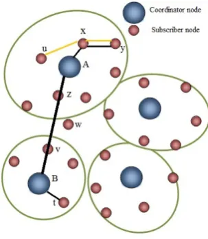
Fig. 3. Example Network
4.4 Exchange of Data Packets
4.4.1 Intra-foraging Region Routing. Within the region, the data packets are routed in a mesh mode. The source node checks for the destination in its routing table to find the next hop node and forwards the packet to it through the WiFi channel. This pro-cess is repeated until the packet reaches the destination node. In Figure 3, nodeywishes to communicate with nodeu. Nodey searches its routing table for destination nodeuand finds the next hop node to bex. Hence, the packet is forwarded to node x. Upon receiving the packet with destinationu, nodexsearches it routing table for nodeu. The next hop touisuitself and the packet is forwarded tou.
4.4.2 Inter-foraging Region Routing. The exchange of data packets outside the region happens in an infrastructure-based mode in which the coordinator nodes form the centralized control. Both WiMAX and WiFi radios are used for such a communication. Consider Figure 3 in which nodeywishes to communicate with nodet. Nodeysearches for nodetin its short routing table. Sincetis not in its region, an entry fortis not present iny’s routing table. Hence,yassumes thattis in another region and forwards the packet to its coordinator nodeAthrough WiFi. The next hop toAfromyisx.
The coordinator nodeAsearches for nodetin its long routing table to find thatBis the destination node’s coordinator, and also the next hop coordinator. Hence, the packet is forwarded toB through WiMAX. Since the coverage range of WiMAX is larger, this forwarding occurs much faster. In the absence of WiMAX, the coordinator nodes would have communicated through WiFi which incurs many more hops. In the example of Figure 3, the WiFi path from the coordinatorAtoBwould be fromAtoz,z tovandvtoB, which as expected would be time consuming. Coordinator nodeBupon receiving the packet, searches its short routing table fortand forwards it totthrough WiFi.
5. IMPLEMENTATION AND ALGORITHM
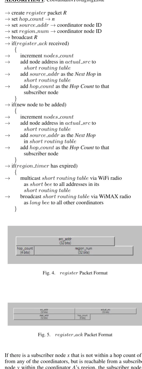
The implementation consists of two sets of algorithms, the Coordinator N ode Algorithm and Subscriber N ode Algorithm, implemented by the coordinator node and the subscriber node respectively. Any node which is equipped with both WiMAX and WiFi radio implements the coordinator node algorithm whereas all other nodes implement the subscriber node algorithm. The two algorithms are subdivided into various functions as explained inALGORIT HMI through VII. Each function can be implemented as a series of interrupts. The coordinator node implementsALGORIT HMI, II and III. The algorithm forms the foraging zones and simultaneously creates theshort routing tablecontaining the list of all nodes in its region. Theregisterpacket and theregister ackpackets are as shown in Figures 4 and 5 respectively.
The coordinator creates theregister packet. Thehop count is set to the number of hops that define a foraging zone(n). In this work, the value ofn is set to 3. Both the source addr and region num are set to the coordinator’s node ID. The region numis also set to the coordinator’s node ID for sim-plicity, since this has to be unique. Theregisterpacket is then broadcast to all the subscriber nodes via the WiFi radio. When the coordinator receives the acknowledgment to itsregister packet from the subscriber node in the form of aregister ack packet, this subscriber node is added to itsshort routing table which maintains the routes to all nodes in its region. The next hop from the coordinator node to this node is the node which passed on this packet to the coordinator, specified by the source addr. The number of nodes in its region, implied by the nodes countis incremented.
ALGORITHM I:CoordinatorForagingZone
→createregisterpacketR →sethop count→n
→setsource addr→coordinator node ID
→setregion num→coordinator node ID
→broadcastR
→if(register ackreceived)
{
→ incrementnodes count
→ add node address inactual srcto short routing table
→ addsource addras theNext Hopin short routing table
→ addhop countas theHop Countto that subscriber node
}
→if(new node to be added)
{
→ incrementnodes count
→ add node address inactual srcto short routing table
→ addsource addras theNext Hop inshort routing table
→ addhop countas theHop Countto that subscriber node
}
→if(region timerhas expired)
{
→ multicastshort routing tablevia WiFi radio asshort beeto all addresses in its
short routing table
→ broadcastshort routing tablevia WiMAX radio aslong beeto all other coordinators
}
Fig. 4. registerPacket Format
Fig. 5. register ackPacket Format
ALGORITHM II:LongRoutingTable
→if(large beereceived)
{
→ add source node intolong routing table → add data into List of all subscriber nodes in
this region }
When a coordinator nodeAreceives alarge bee packet from another coordinatorB, it adds the address ofBalong with the list of all the node IDs sent in the packet into itslong routing table.
ALGORITHM III:HandleData
→if(data packet received)
{
→ search for the destination in short routing table
→ if(found)
→ forward the packet to theN ext Hop corresponding to this destination
→ else
{
→ search for the destination in long routing table
→ if(found)
→ forward the packet to the N ext hop coordinator node corresponding to this destination
→ else
→ discard packet
} }
Once a data packet is received, the coordinator node first searches for the destination address in its region, i.e; the shortroutingtable. If the destination is in its own region, it forwards the packet to the node through the next hop node through WiFi. In case the destination is not found in its region, it searches for destination in itslongroutingtableand forwards the packet to the corresponding coordinator node through WiMAX. If the packet’s destination is neither found in its shortroutingtablenor in itslongroutingtable, the address is invalid and the packet is discarded.
The subscriber node implementsALGORIT HM SIV, V, VI and VII. When the subscriber node x receives the register packet sent by the coordinator node, if it does not have a region yet, it updates itsregion number to the one sent in the packet and sends an acknowledgment to the sender through the register ack packet. The node from which this packet was received is saved as the next hop to the coordinator. The hop countin the packet is then decremented and the packet is further broadcast if the newhop countis greater than zero. This is done to cover a radius ofnhops around the coordinator into the region. Once ahop countof zero is reached, it is implied that a radius ofnhops is covered and the packet is discarded. This functionality is implemented inALGORIT HMIV. Any node that is more thannhops away from any of the coordi-nators cannot be a part of any region using the abovehopcount mechanism. In the case where such nodes are reachable to other subscriber nodes, they can be drawn into the nearest region. When theregiontimer, which is started at the beginning times out, if the nodexdoes not have a region number, it broadcasts a region request bee. The subscriber node y that receives it responds with a region request bee ack1 to inform x about itsregion numberto whichx will now belong. Node x acknowledges with region request bee ack2 in order to
confirm toythat its coordinator can be informed to addx. In case where there are many such nodesythat are reachable to nodex, xsends theregion request bee ack2only to the nodeywhose reply was received first. Hence, the other nodes do not inform their coordinators to addxto their regions.ALGORIT HMIV implements this mechanism.
ALGORITHM IV:SubscriberForagingZone
→createrouting table →startregiontimer
→if(register Rreceived)
{
→ if(region number=-1)
{
→ updateregion number→region num from the received packetR
→ coord next hop→source addr → createregister ackRA
→ setRA.dest addr→sourceaddr
ofR
→ set bothsource addrandactualsourceto node objID
→ sendRA
→ extractHopCountfromRand decrement it
→ if(Hop Count→0)
→ broadcastRwith decremented Hop Count
→ else
→ discardR }
→ else
→ discardR }
ALGORITHM V:Initialize
→if(regiontimer has expired andregion numberis not yet set)
→ broadcastregion request beepacket requesting for a region
→if(region request beereceived)
→ sendregion numbervia
region request bee ack1to the source
→if(region request bee ack1received)
{
→ updateregion number→region num of the received packet
→ sendregion request bee ack2to the sender
}
→if(region register bee ack2received)
ALGORITHM VI:RoutingTable
→if(short beeSreceived)
{
→ for each address in the packet data
{
→ search for address in the routing table
→ if(found)
{
→ if(Hop Count+1hop count in the routing table)
{
→ updatehop count→HopCount in the received packet
→ updatenext hop→source of the packet
→ change→true
} }
→ else
{
→ add all the address in thedataof Sto the routing table
→ update eachHop Countentry as
the number of hops from this node to the coordinator and the number of hops from the coordinator to the corresponding node(provided in the packet)
→ change→true
} } → if(change)
→ exchange routing table viashort bee }
→find its own node ID in theroutingtableand set N extHopandHopCountto itself and 0 respectively
→multicastroutingtableasshort beeto all the nodes in its region
In the case where the subscriber nodex receives ashort bee packet from another subscriber nodey, an entry for the node ID in the packet will already be present in theroutingtable. Hence, for each of the entries, the nodexchecks if the hop count spec-ified in the packet plus one is less than theHop Countfor that node in itsroutingtable, in which case, theNext Hopis updated to nodeyand theHop Countis updated to the hop count against this node in the packet plus one. One is added to the hop count specified in the packet to account for the one hop from nodexto nodeywhich sent the packet. When the nodeyis an immediate neighbour ofx, the hop count specified in the packet against node yis zero. Hence, in theroutingtableofx, theHopCounttoy becomes one; rightly representing thatyis an immediate neigh-bour ofx. Theroutingtableis then multicast to all the nodes in its region and hence, all nodes update their routing tables to the optimal paths. The above process is explained in algorithms V and VI.
As explained in algorithm VII, the subscriber node, on receiv-ing thedata packet, checks if the packet was destined to it-self, in which case, it passes on the packet to the higher lay-ers. If the destination is not itself, it searches for the destination in itsroutingtable, and if it is found, the packet is forwarded to theNext Hop. If the destination address does not exist in its routingtable, the implication is that the packet is destined to a node in another region. Hence, the packet is forwarded to the
co-ordinator node of this region.
ALGORITHM VII:ReceiveData
→if(datapacket received)
{
→ if(dest=node objID)
→ pass the packet to the transport layer
→ else
{
→ search fordest addrin routing table
→ if(found)
→ send the packet tonext hop
→ else
→ send the packet to the coordinator node
} }
6. PERFORMANCE ANALYSIS
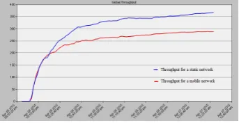
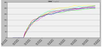
The algorithm was run for various scenarios by varying the different parameters. The graph shown in Figure 6 was obtained by running the simulation for 2 hour 30 minutes, the data rates of WiMax and WiFi being set to 50 Mbps and 100 Mbps. The coverage range of WiMax was set to 5000 m and that of WiFi to 750 m. The graph shows the comparison of throughputs for static and mobile networks. It can be seen that the throughput of the static network is higher than that of the mobile network. This is because the topology of the static network does not change, hence the routes are formed only once, during the network setup. Once the routes are set, no new routes are to be formed and only data packets are exchanged, increasing the throughput of the network. In the mobile network, the nodes are moving, and routes change. New routes are formed by exchanging the bee packets at a frequency of 20 s. Hence, at an interval of 20 s, along with data packets, bee packets are also exchanged which decreases the overall network throughput. Also, the frequency of bee packet exchange may not be in sync with the time when the nodes move out of the region. In such a case where some of the nodes have gone out of the foraging region, but the new routes are not yet updated, the nodes might be either unreachable or the routes to them may not be optimized, further decreasing the throughput.
Fig. 6. Throughput of static v/s mobile network
Fig. 7. Throughput for various speeds of motion
Table 4. Distance moved by the node in 8 seconds Speed of motion
(m/s)
Distance moved (m)
Subscriber node’s location
10 80 Neither
neigh-bors’ range nor region
100 800 Neighbors’
range
200 16000 Neighbors’
range
250 2000 Neighbors’
range
275 2200 Neighbors’
range and region
300 2400 Neighbors’
range and region
Fig. 8. Average speed v/s maximum throughput
The distance formula is as follows:
distance moved=speed×time (1)
Using equation 1 the distance moved by a node in 8 seconds for various speeds is calculated.
The node can either remain in a relatively same position, go out of the WiFi range of its neighbor or go out of its region. Depending on the speed of the node, the bee packets must be exchanged at optimal intervals so that the overall network throughput doesnot drop. In this work, the bee packets are exchanged at a regular interval of 8s for various speeds, and the variation in the overall network throughput is studied. In this work, a hop limit of 3 is considered for the formation of regions. When the speed of the node is 10 m/s, in 8 seconds, the node moves a distance of only 80 metres, which is less than the WiFi coverage range. Hence, the position of the node in the network has not changed much and there is no need to find new routes. But, by the end of 8 seconds, bee packets are exchanged and new routes are formed, which is wasteful of resources. This unnecessary formation of routes results in low overall network
throughput.
The nodes moving at a speed of 100 m/s, 200 m/s, 250 m/s and 275 m/s cover distances of 800m, 1600m, 2000m and 2200m respectively in 8 seconds. In such a case, the node moves out of the WiFi range of its neighbors but remains within its region. Hence, the frequency of updation of the routing tables which happens at every 8 seconds is apt for this range of node speeds resulting in higher throughputs.
Fig. 9. An example network
Fig. 10. An example network showing routes before and after a node moves
Once the speed is increased further, the frequency of updation of the routing tables is smaller than that required; i.e, the nodes change their routes much faster than they are updated, resulting in a throughput fall. This can be seen in the graph in Figure 8 for a speed of 300 m/s, where, the node moves a distance of 2400m in 8 seconds. As it can be seen from the Figure 9, the maximum possible radius of 3 WiFi hops is 2250 m since each WiFi hop is 750 m.
Fig. 11. Throughput for hop limits 3 through 6 for static network 13
Fig. 12. Hop limit v/s maximum throughput for static network 13
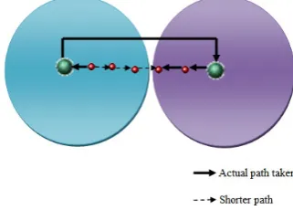
The performance of the network was observed by varying the parameter hop limit used for forming the foraging regions. The graph in Figure 11 shows the throughputs for hop limits from 3 to 6 for the static network topology shown in Figure 13. For easier analysis, the maximum throughput is plotted against hop limit and is shown in Figure 12. The coverage range of WiMAX was considered to be 5000 metres and that of WiFi to be 750 metres. It can be seen that the overall network throughput increases gradually. This is because approximately 6.67 WiFi hops equals one WiMAX hop. When the hop limit was considered to be 3, a source nodex, four WiFi hops away from the destination nodeyon the same side of the coordinator node fall into different foraging regions, resulting in the data packets taking a longer path as shown in the Figure 14. The same reason applies for hop limits of 4 and 5. The throughput is seen to be maximum for hop limit 6 since approximately six WiFi hops make one WiMAX, making it the apt hop limit for the chosen WiMAX and WiFi coverage ranges. It is expected that for a hop limit of 7, the throughput decreases since two WiMAX hops will be required to reach out to this distance against a shorter distance of 7 WiFi hops. From the observation, it can be inferred that the right hop limit can be obtained by equation 2.
Hoplimit=f loor(W iM AXcoveragerange W iF icoveragerange
) (2)
7. CONCLUSIONS
Interoperability between WiMAX and WiFi was exploited using an algorithm based on the Bee-hive algorithm. The implementa-tion of the algorithm was discussed in detail. From the observa-tions, it can be concluded that the overall network performance given by throughput and end-to-end delay was higher for a static network since routes do not change frequently. In the case of a mobile network, it was seen that the frequency of formation of new routing tables must depend on the average speed of the nodes. The hop limit must be chosen depending on the available
Fig. 13. Static network used to study the dependence of throughput on hop limit
Fig. 14. Path taken when communicating nodes are in different forag-ing regions
WiMAX and WiFi coverage ranges.
As a part of future work, a mathematical model for the depen-dency of throughput on various factors such as hop limit, speed of the nodes can be developed. A more detailed, corner-case study of the algorithm’s behavior and its ability to tolerate faults in the network nodes and links can be made.
8. REFERENCES
[1] WiMAX and the IEEE 802.16 Air Interface Standard-April 2010, WiMAX Forum
[2] S. Banerji and R. S. Chowdhury,“Wi-Fi & WiMAX: A Com-parative Study”, arXiv preprint arXiv:1302.2247, 2013. [3] Abhishek Alfred Singh (2011).“Traffic Splitting In Hybrid
Multi-radio Ad-hoc Networks”(M.E. Dissertation) Banga-lore University.
[4] Proposed TGac Draft Amendment Document, IEEE 802.11-10/1361r3, Jan- uary 18,2011
[5] K. Chebrolu, B. Raman, and S. Sen, “Long-Distance 802.11b Links: Performance Measurements and Experi-ence”, in Proceedings of the 12th annual international con-ference on Mobile computing and networking. ACM, 2006, pp. 74-85.
[6] Opent Modeler, Opnet Modeler Documentation Set, Version 14.5
[7] Jeffrey G. Andrews, Arunabha Ghosh, and Rias Muhamed, “Fundamentals of WiMAX: Understanding Broadband Wireless Networking”, Prentice Hall, 2007
[8] IEEE 802.16m standard, IEEE standard for Information Technology Part 16, Amendment 3, 2011
[10] Silva, H., Figueiredo, L., Rabadao, C., and Pereira, A., “Wireless networks interoperability Wifi WiMAX Han-dover”, Proceedings of the 2009 Fourth International Con-ference on Systems and Network Communications, pp 100-4, Sept. 2009
[11] Gracias, M., Knezevic, V., and Esmailpour, A., “Interoper-ability between WiMAX and WiFi in a testbed environment”, 24th Canadian Conference on Electrical and Computer En-gineering, pp. 1144-48, May 2011
[12] Connie Ribeiro“Bringing Wireless Access to the Automo-bile: A Comparison of Wi-Fi, WiMAX, MBWA and 3G”, Pro-ceedings of the 21st Computer Science Seminar
[13] Sangeetha J., and Kumar, S., A comparative study on WiFi and WiMAX networks,“IEEE International Conference on Computational Intelligence and Computing Research”, pp. 1-5, Dec. 2010
[14] Ghazisaidi, N., Kassaei, H., and Bohlooli, M.S., “Integra-tion of WiFi and WiMAX networks”, International Confer-ence on Advances in Mesh Networks, pp. 1-6, June 2009
[15] Kim, J.-O., Davis, P., Ueda, T. and Obana, S. (2010), “Splitting Down- link Multimedia Traffic over Wimax and Wifi Heterogeneous Links Based on Airtime-Balance”, Wirel. Commun. Mob. Comput.. doi: 10.1002/wcm.999 [16] Bruno, R.; Conti, M.; Gregori, E.;“Mesh networks:
com-modity multihop ad hoc networks”,Communications Maga-zine, IEEE, vol.43, no.3, pp. 123- 131, March 2005
[17] Lima, M., A. Dos Santos, and Guy Pujolle.“A survey of survivability in mobile ad hoc networks”. Communications Surveys & Tutorials, IEEE 11, no. 1 (2009): 66-77. [18] Brewer, E.A; Katz, R.H.; Chawathe, Y.; Gribble, S.D.;
Hodes, T.; Giao Nguyen; Stemm, M.; Henderson, T.; Amir, E.; Balakrishnan, H.; Fox, A; Padmanabhan, V.N.; Se-shan, S.,“A network architecture for heterogeneous mobile computing”, Personal Communications, IEEE, vol.5, no.5, pp.8,24, Oct 1998 doi: 10.1109/98.729719.
[19] Chuanxiong Guo; Zihua Guo; Qian Zhang; Zhu, Wenwu, “A seamless and proactive end-to-end mobility solution for roaming across heterogeneous wireless networks”, Selected Areas in Communications, IEEE Journal on vol.22, no.5, pp.834,848, June 2004 doi: 10.1109/JSAC.2004.826921. [20] Perkins C., Das S.,“Ad hoc On-Demand Distance Vector
Routing”, RFC 3561, July 2003
[21] R. Draves, J. Padhye, and B. Zill,“Routing in Multi-Radio, Multi-Hop Wire- less Mesh Networks”, Proc. of MobiCom 04, pp. 114-128, Sept.-Oct. 2004
[22] Azad, Md Saiful, Mohammad Moshee Uddin, Farhat An-war, and Md Arafatur Rahman, “Performance Evaluation of Wireless Routing Protocols in Mobile WiMAX Environ-ment”, IAENG International Conference on Communication Systems and Applications. 2008.
[23] Shafiee, K., Attar, A., and Leung, V.C. M., “WLAN-WiMAX double technology routing”, IEEE Vehicular Tech-nology Conference, pp. 1-6, Sept. 2011
[24] Ibanez, S.R., Santos, R.A., Licea, V.R., Block, A.E., Ruiz, M.A.G.,“Hybrid WiFi-WiMAX Network Routing Protocol”, Electronics, Robotics and Automotive Mechanics Confer-ence, 2008. CERMA 08 , vol., no., pp.87-92, Sept. 30 2008-Oct. 3 2008, doi: 10.1109/CERMA.2008.24
[25] Bonabeau, M. Dorigo, and G. Theraulaz.“Swarm Intelli-gence: From Natural to artificial Systems”, Oxford Univer-sity Press, 1999.
[26] B.Bar an and R.Sosa.“A new approach for Antnet Rout-ing”,Proceedings of the Ninth International Conference on Computer, Communications and Networks, 2000, pp 303-308.E.
[27] Horst F. Wedde, Muddassar Farooq, and Yue Zhang. “Bee-Hive:An efficient routing algorithm inspired by Bee behav-ior”, Springer-Verlag, 2004, pp-83-94.