IJEDR1803063
International Journal of Engineering Development and Research (
www.ijedr.org
)
352
Novel Skip Control Method for Improving the
Efficiency of Micro-Inverters Under Light Load
Conditions
1
Ming-Hung Yu,
2Paul C.-P. Chao
1 Institute of Electrical and Control Engineering, 1 National Chiao Tung University, Hsinchu, Taiwan
_____________________________________________________________________________________________________ Abstract—This paper presents a novel skip control method for improving the efficiency of micro-inverter at low power
inputs. The proposed control method assesses the operating mode of a system according to the energy of an input capacitor. If the energy is higher than a reference level, the system operates in a continual mode; otherwise, the system operates in a discontinue mode to improve the light load efficiency. Finally, a 200-W micro-inverter is implemented to verify the proposed control method, The implemented micro-inverter was used in an experiment to compare the efficiency of operations with and without the proposed skip control method. This comparison was conducted to verify whether the proposed skip control operation improved the operating efficiency under light load conditions.
Index Terms—micro-inverter, skip control method, light load, photovoltaic.
_____________________________________________________________________________________________________
I.INTRODUCTION
Because energy and environmental problems have received considerable attention worldwide, developing power products that are based on green clean energy has become increasingly vital. Generating renewable energy typically involves using energy conversion devices to convert energy source into electric power that is subsequently supplied to a load or grid-tie power system. However, renewable energy sources are intermittent and unreliable. Therefore, how to improve the conversion efficiency of converters is highly crucial for renewable energy systems.
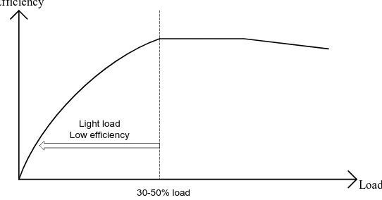
Numerous techniques have been proposed for improving the efficiency of converters, and in most of such techniques, emphasis has been placed on implementing new topologies to reduce the switching loss or conduction loss of power converters[1–3]. Although optimal improvements in the peak conversion efficiency have been reported, the improvements in the efficiency of light power operating modes are limited. Figure 1 illustrates the efficiency curve of a typical power converter, indicating that the system efficiency is extremely low in the light input operating mode and that this mode demonstrates more power losses than the medium load and full load modes do.
Skip control techniques have been proposed for reducing the power loss of power converters under light load condition. Therefore, DC-DC converters have been prevalently used for improving the operating efficiency under light load conditions [4– 6]. Skip mode for DC-AC inverters were recently proposed in [7-9]to improve the efficiency in wide load range without increasing the cost or complexity of the design by reducing the dominant losses depending on the load current.; however, the control strategy in these studies requires sensing the input DC current for executing the skip control process. When a converter operates in a low power mode, the current decreases and affects the accuracy of the sensor. Therefore, the power converter cannot precisely reflect diverse input powers, reducing the generation benefits. According to the design and driving concept developed by [7-9], The study presents a highly precise pulse skip control method that operates according to the energy of an input capacitor, so that the accuracy of the sensor and the power generation could be improved.
Fig. 1 efficiency curve of typical power converter
Load Efficiency
Light load Low efficiency
IJEDR1803063
International Journal of Engineering Development and Research (
www.ijedr.org
)
353
The rest of this paper is organized as follows: Section II describes the principle of the proposed skip control method. Section III presents experimental results. Finally, Section 4 provides the conclusion.II.SKIPPINGCONTROLMETHOD i. Control method
The miro-inverter operates at extremely low efficiency levels because of the light-load condition as the inverter drive and switching losses become dominant, so when the energy from photovoltaic(PV) panel is under light load condition, the efficiency of the micro-inverter is also low. therefore, when the power source lower than a certain level, the inverter stop to deliver energy into the grid continuous mode and change the control mode into the pulse-skipping operating mode.
Fig. 2 illustrates a pulse-skipping operating mode. During the pulse-skipping mode, the system is disabled and the ambient light energy obtained from the PV module is used to charge the input capacitor. Until the voltage level of capacitor reaches upper limit level, the system subsequently delivers energy under maximum efficiency operating condition to the grid through the micro-inverter. When the voltage of the input capacitor drops to the low voltage limit value, the recharge of the input capacitor is initiated and the system stop again.
ii. System block and control flowchart
Fig. 3 shows the proposed system block. The MCU operates in a continuous mode or skip control mode controlled by a maximum power point tracking (MPPT) controller. In the skip operating mode, the pulse-width modulation (PWM) signal controlled by the skip controller and inverter output discontinuous power to grid; when the output power is greater than the reference power level, the controller switches to the continuous mode and inverter outputs continuous power to the ac grid.
IJEDR1803063
International Journal of Engineering Development and Research (
www.ijedr.org
)
354
Fig. 3 Proposed system blockFig. 4 Flowchart of the proposed inverter
IJEDR1803063
International Journal of Engineering Development and Research (
www.ijedr.org
)
355
Fig. 5 Skip current controllerFig. 5 illustrates the proposed skip current controller. The error value ΔW is derived by calculating the input capacitor energy between [t0–t1] and [t1–t2] on Fig. 2; ΔW is regulated by the PI controller and compared with VPV, and the value serves as a reference
current for current loop output PWM signal.
III.EXPERIMENTALRESULTS
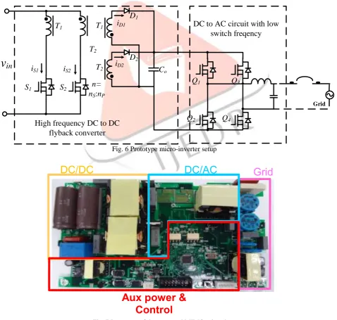
A prototype of 200-W micro-inverter was created to verify the parameter optimization for the proposed pulse-skipping control method (Fig. 6). The predesigned converter circuitry is implemented on a printed circuit board (PCB; size: 18 cm × 12 cm), as depicted in Fig. 7. Table 1 lists the design parameters of the prototype micro-inverter. Fig. 7 reveals that the PCB comprises a transformer, two switching metal–oxide–semiconductor field-effect transistor (MOSFET) devices and two diodes for high frequency DC to DC converter, four MOSFET switches for DC to AC circuit. To reduce switching losses, switch on secondary side of the inverter was designed to operate at low frequency, and the primary side switch was operated at line frequency.
Fig. 6 Prototype micro-inverter setup
Fig. 7 Prototype of the proposed MIMO micro-inverter Table 1 Design parameter of the prototype micro-inverter
v
in
S
1S
2T
1T
2T
1T
2i
S1i
S2i
D1i
D2D
1D
2C
on=
n
S:
n
PGrid
Q
1Q
3Q
4Q
2DC to AC circuit with low
switch freqency
High frequency DC to DC
flyback converter
DC/DC
DC/AC
Grid
IJEDR1803063
International Journal of Engineering Development and Research (
www.ijedr.org
)
356
Input DC voltage 25~55V
Output AC voltage 220V
Maximum output current 1.136A
Maximum output power 200W
Switching frequency 50kHz
Transformer Inductance(Lm)
18uH
Type of transformer PQ32/20
DC to DC switches (S1 and S2)
IPB107N20N3 DC to DC diodes
(D1 and D2)
C2D05120 DC to DC switches
(Q1~Q4)
STB18NM80 Output filter inductor 1.5mH Output filter capacitor 1uF
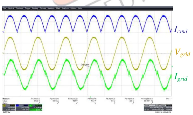
Fig. 8 illustrates the experimental results obtained when the converter is operated in continue mode. When the micro-inverter started, the energy from the PV cell is delivered to the AC output follow the waveform of the grid voltage. Fig. 9 shows the experimental results of the pulse-skipping operating mode. During the pulse-skipping mode, the system is disabled and the ambient light energy obtained from the PV module is used to charge the input capacitor. Until the voltage level of capacitor reaches upper limit level, the system subsequently delivers energy under maximum efficiency operating condition to the grid through the micro-inverter. When the voltage of the input capacitor drops to the low voltage limit value, the recharge of the input capacitor is initiated and the system stop again.
The conversion efficiencies obtained from the experiments are presented in Fig. 10. The highest efficiency is 95.32% under 140 Watt condition, whereas the lowest efficiency curve corresponded to a power level of 20 W and the efficiency has been improved from 80% to 87.51% and the efficiency curves are greatly improved to 90% when the pulse-skipping strategy was employed under light loads. Experimental results verify that pulse-skipping control can effectively improve light load efficiency. The conversion efficiencies obtained from the experiments are presented in Fig. 24. The highest efficiency is 95.32% under 140 Watt condition. whereas the lowest efficiency curve corresponded to a power level of 20 W, the efficiency without and with skipping control are 80% and 87.51%, respectively. The efficiency curves are greatly improved to near 90% when the pulse-skipping strategy was employed under light loads. Experimental results verify that pulse-pulse-skipping control can effectively improve light load efficiency.
Fig. 8 Experimental results under continue mode
I
cmd
V
grid
IJEDR1803063
International Journal of Engineering Development and Research (
www.ijedr.org
)
357
Fig. 9 Pulse-skipping operating mode experimental resultsFig. 10 Experimental results revealing efficiencies of the proposed micro-inverter.
IV.CONCLUSIONS
This paper proposes a pulse skipping control method for improving the efficiency of micro-inverters under light loads. The proposed control method can be used to achieve high efficiency under light load conditions by reducing dominant losses depending on the load current. Finally, the simulation and experimental results revealed efficiency improvements under light loads, where the inverter efficiency was maintained around 90% even under light load conditions.
REFERENCES
List and number all bibliographical references in 10-point Times, single-spaced, at the end of your paper. When referenced in the text, enclose the citation number in square brackets, for example: [1]. Where appropriate, include the name(s) of editors of referenced books. The template will number citations consecutively within brackets [1]. The sentence punctuation follows the bracket [2]. Refer simply to the reference number, as in “[3]”—do not use “Ref. [3]” or “reference [3]”. Do not use reference citations as nouns of a sentence (e.g., not: “as the writer explains in [1]”).
Unless there are six authors or more give all authors’ names and do not use “et al.”. Papers that have not been published, even if they have been submitted for publication, should be cited as “unpublished” [4]. Papers that have been accepted for publication should be cited as “in press” [5]. Capitalize only the first word in a paper title, except for proper nouns and element symbols.
For papers published in translation journals, please give the English citation first, followed by the original foreign-language citation [6].
[1] Mohammad Ali Rezaei, Kui-Jun Lee, Alex Q. Huang, “A High-Efficiency Flyback Micro-inverter With a New Adaptive Snubber for Photovoltaic Applications,” IEEE Transactions on Power Electronics, vol. 31, pp. 381–327, Issue 1, Jan. 2016.
[2] Woo-Jun Cha, Yong-Won Cho, Jung-Min Kwon, Bong-Hwan Kwon, “Highly Efficient Microinverter With Soft-Switching Step-Up Converter and Single-Switch-Modulation Inverter,” IEEE Transactions on Power Electronics, vol. 62, Issue 6, pp. 3516–3523, June 2015.
IJEDR1803063
International Journal of Engineering Development and Research (
www.ijedr.org
)
358
[4] Ferran Reverter, Manel Gasulla, “Optimal Inductor Current in Boost DC/DC Converters Operating in Burst Mode UnderLight-Load Conditions,” IEEE Transactions on Power Electronics, vol. 31, Issue 1, pp. 15–20, July 2016.
[5] Jian Chen, Takahide Sato, Koji Yano, Hironobu Shiroyama, Makoto Owa, Masayuki Yamadaya, “An Average Input Current Sensing Method of LLC Resonant Converters for Automatic Burst Mode Control,” IEEE Transactions on Power Electronics, vol. 32, Issue 4, pp. 3263–3272, April 2017.
[6] M. Narimani, G. Moschopoulos, “An Investigation on the Novel Use of High-Power Three-Level Converter Topologies to Improve Light-Load Efficiency in Low Power DC/DC Full-Bridge Converters,” IEEE Transactions on Industrial Electronics, vol. 61, Issue 10, pp. 5690–5692, Oct. 2014.
[7] Zheng Zhao, Kuan-Hung Wu, Jih-Sheng Lai, Wensong Yu, “Utility grid impact with high penetration PV micro-inverters operating under burst mode using simplified simulation model,” 2011 IEEE Energy Conversion Congress and Exposition, Phoenix, AZ, USA, pp. 3928–3932, Sept. 2011.
[8] Haibing Hu, Wisam Al-Hoor, Nasser H. Kutkut, Issa Batarseh, Z. John Shen, “Efficiency Improvement of Grid-Tied Inverters at Low Input Power Using Pulse-Skipping Control Strategy,” IEEE Transactions on Industrial Electronics, vol. 25, Issue 12, pp. 3129–3138, Dec. 2010.