LITHIUM DEPOSITION IN SOLID POLYMER
ELECTROLYTE BATTERIES
A thesis presented to the University of London in partial fulfillment of the
requirements for the degree of Doctor of Philosophy.
by
JONG-CHUL KIM
UCL Chemistry Department Christopher Ingold Laboratories
20 Gordon Street London WC1H OAJ
ProQuest Number: U644119
All rights reserved
INFORMATION TO ALL USERS
The quality of this reproduction is dependent upon the quality of the copy submitted.
In the unlikely event that the author did not send a complete manuscript and there are missing pages, these will be noted. Also, if material had to be removed,
a note will indicate the deletion.
uest.
ProQuest U644119
Published by ProQuest LLC(2016). Copyright of the Dissertation is held by the Author.
All rights reserved.
This work is protected against unauthorized copying under Title 17, United States Code. Microform Edition © ProQuest LLC.
ProQuest LLC
789 East Eisenhower Parkway P.O. Box 1346
ABSTRACT
This thesis is concerned with lithium deposition in solid polymer electrolyte
batteries. Passivating layers are developed on the electrode even in polymer
electrolytes as the cycling proceeds and perturbation o f the morphology o f the
lithium deposited may be expected.
In this project, cyclic voltammetry was used as a probe for the presence o f
electroactive impurities in polymer electrolytes. The main electroactive impurity
present was water. It was demonstrated that oxygen as well as water could affect
the voltammetric behavior o f polymer electrolyte test cells.
A galvanostatic experiment and theoretical analysis identified the presence o f
a critical current where the concentration o f Li+ at the cathode surface approached zero. The expected dependence o f the critical current on the polymer electrolyte
thickness, the Li+ concentration and the Li+ diffusion coefficient was found. It was shown that the observed critical current density gradually decreased with the
number o f cycles because side reactions might produce the passivating layers
during cycling.
In-situ
microscopic observation o f the electrochemical deposition o f lithiumon a Ni substrate was carried out in poly(ethylene oxide) based electrolytes
observed at a current density lower than the corresponding critical current density.
A transition to dendritic growth was seen at a current density far higher than the
corresponding critical current density.
It was shown by the in-situ observation that dendrites grew via fine particles
in the polymer electrolytes. These fine particles could accelerate the rate o f side
reaction between lithium and impurities by generating a high surface area and
reactivity. They also changed the morphology o f the lithium deposited in
subsequent cycles towards dendrites. The presence o f a passivating layer o f
Table o f contents
Abstract
Table o f contents
Table o f figures
Table o f tables
Acknowledgement
Chapter 1. Introduction
1.1 Lithium Polymer Batteries (LPB)
1.1.1. Background on lithium batteries
1.1.2. Lithium polymer batteries
1.1.3. Application in electric vehicles
1.2. Polymer Electrolytes
1.2.1. Polymers
1.2.2. Conduction in polymer electrolytes
1.2.3.Salt effect on the conductivity: LiC104 vs.LiCF3S 0 3
1.3. Lithium Passivation
1.3.1. Lithium passivation in liquid electrolytes
1.3.2. Lithium passivation in polymer electrolytes
1.3.3. Effect o f the deposit morphology on battery performance
1.3.4. Lithium passivation in hybrid polymer electrolyte
1.4 The objectives o f the project
References
52
54
Chapter 2. Experimental techniques
2.1. Materials
2.2. Electrolyte preparation
2.3. Electrochemical experiments
2.3.1. Cyclic voltammetry
2.3.2. A galvanostatic ramp experiment
2.3.3. Cycling efficiency
2.4. Microscopic observation
2.4.1. Optical microscopy in-situ
2.4.2. FT-IR microprobe measurement in-situ
Chapter 3. Results
3.1. Cyclic voltammetry
3.1.1. Cyclic voltammetry o f a L i/P E 0 8LiC104/Ne cell
3.1.2. Cyclic voltammetry o f a L i/P E 0 8LICF3S 0 3/Ni cell
3.2. Critical current in a polym er electrolyte cell
3.2.1. Theory
3.2.1.1. The critical current
3.2.2. A measurement o f the critical current in a P E 0 8LiC104 electrolyte
3.2.2.1. Temperature effect on the critical current
3.2.2.2. SPE thickness effect on the critical current
3.2.2.3. A calculation o f the diffusion coefficient
3.2.2.4. Effect o f the substrate shape on the critical current
3.2.2.5. Cell cycling effect on the critical current
3.2.3. A measurement o f the critical current in a P E 0 8LiCF3S 0 3 electrolyte
3.2.3.1. Effect o f the substrate shape on the critical current
3.2.3.2. Cell cycling effect on the critical current
3.2.4. Cycling efficiency vs. critical current
3.3.Microscopic observation o f Li deposit morphology
3.3.1. Experimental investigation o f the morphology o f the Li deposited in polymer electrolyte at elevated temperature
3.3.2. Deposition morphology in P E 0 8LiC104
3.3.3. Deposition morphology in P E 0 8LiC 104
3.3.4. Variation o f deposition m orphologies during cycling
References
Chapter 4. Discussion o f results
4.2. The critical current . , ^ 1 1j
4.2.1. P E 0 gLiC104 vs.P E 0 8LiCF3S 0 3
4.2.2. Variation o f the critical current density during
cycling 117
4.2.3. Cycling efficiency vs. critical current ^
4.3. Effect o f the critical current on the deposit morphology
^ 2
References
Chapter 5. Conclusion
131Table of figures
1-1 Configuration o f polymer electrolyte cell
1-2 Various regions existed in polymers
1-3 The irreversible capacity loss mechanism showing the effect o f deposit morphology on the formation o f the passivating film by generating high surface area.
1-4 A schematic presentation o f the concentrated current density on the electrode
1-5 Proposed mechanism o f the formation o f particle-like Li during discharging and the formation o f needle-like Li during charging in organic electrolytes
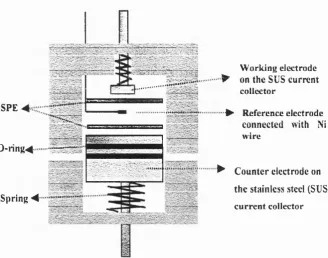
2-1 Three-electrode cell used in electrochemical experiments in this project, Ni sheet was used as w orking electrode and lithium used as
reference and counter electrode
2-2 Electronic arrangement for measurements o f the critical current and (b) scheme illustrating how to generate a ramp current.
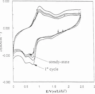
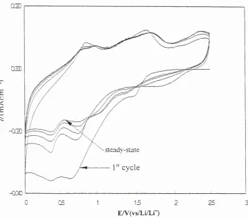
3-1 Cyclic Voltammogram o f lithium deposition and dissolution on Ni vs. cycle number in PEO gLiC104 at sweep rate: 10 mV/sec, cell operating-temperature : 100°C
3-2 Cyclic Voltammogram o f the consecutive lithium deposition and dissolution process on Ni in P E 0 8LiC104 at 100°C obtained at sweep rate o f 20 mV/sec.
3-3 Cyclic Voltammograms obtained at different inversion potentials at the sweep rate o f 20 mV/sec
3-4 Cyclic Voltammogram o f lithium deposition and dissolution on Ni in P E 0 8LiC104 at 100°C vs. cycle number showing oxygen effect on voltammetric behavior at sweep rate o f 20 mV/sec
3-5 Effect o f the drying condition o f polym er electrolytes on the cyclic voltammetry o f N i electrode in P E 0 8LiC104 at 100°C
3-6 FT-IR spectrum o f P E 0 8LiC104
3-7 Effect o f sweep rate on the cyclic voltammetry o f Ni electrode in P E 0 8LiC104, Sweep rate: 50 mV/sec
3-8 Cyclic Voltammogram o f lithium deposition and dissolution on Ni electrode in P E 0 8L iC I04 vs. cycle num ber at sweep rate o f 100
mV/sec
3-10 Cyclic Voltammogram o f lithium deposition and dissolution on Ni in P E 0 8LiCF3S 0 3 vs. cycle number, Reference electrode: Li/Li+, Sweep rate: 50 mV/sec
3-11 Cyclic Voltammogram o f lithium deposition and dissolution on Ni in P E 0 gLiCF3S 0 3 vs. cycle num ber at sweep rate o f 100 mV/sec
3-12 Cation concentration profile in polymer electrolyte and electrodes
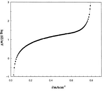
3-13 Variation o f potential difference w ith applied ramping current density for lithium deposition on N i electrode in P E 0 8LiC104 at
100°C
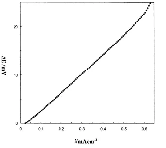
3-14 Potential difference vs. applied ramping current density for calculation o f conductivity in P E 0 8L iC I0 4 at 100°C
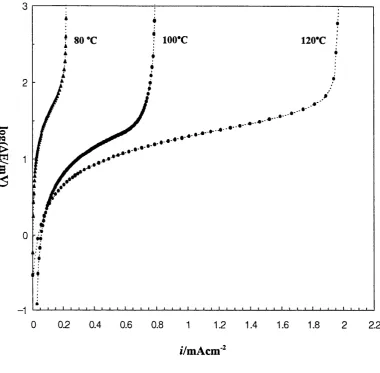
3-15 (a) Temperature effect on the critical current density for lithium deposition on N i electrode in P E 0 8LiC104
(b) Critical current vs. temperature
3-16 Conductivity against tem perature for P E 0 8LiC104
3-17 (a) Effect o f SPE thickness on the critical current density o f lithium deposition on Ni electrode in PEO gLiC104 at 100°C
(b) R vs. h (thickness)
3-19 Curves o f potential difference across the cell (AE) vs. applied
ramping current density (i) with cycle number in P E 0 8LiC104
3-20 Critical current density vs. cycle num ber for P E 0 8LiC104
3-21 Calculated conductivity vs. cycle num ber for P E 0 8LiC104
3-22 Variation o f potential difference w ith applied ramping current for lithium deposition on Ni electrode in P E 0 8LiCF3S 0 3 at 100°C
3-23 (a) Temperature effect on the critical current density for lithium deposition on Ni electrode in P E 0 8L iC F 3S 0 3
(b) Critical current density vs. tem perature
3-24 (a) Effect o f SPE thickness on the critical current density o f lithium deposition on Ni electrode in P E 0 8LiC F3S 0 3 at 100°C
(b) R vs. h (thickness)
3-25 Temperature vs. conductivity o f lithium in P E 0 8LiCF3S 0 3 at various temperatures
3-26 Effect o f the substrate shape o n the critical current o f P E 0 8LiCF3S 0 3
3-27 Curves o f potential difference across the cell (AE) vs. applied ramping current density (i) with cycle num ber in P E 0 8LiCF3S 0 3 at
3-28 Changes in the calculated conductivity with cycle number for P E 0 8LiCF3S 0 3 at 100°C,
3-29 Variation o f stripping efficiency w ith deposition current density in P E 0 8LiC I04
3-30 Variation o f stripping efficiency w ith deposition current density in P E 0 8LiCF3S 0 3
3-31 Typical lithium deposits in a polym er electrolyte (P E 0 8LiC104) at 100°C obtained after deposition at 3.0 mA/cm2for 20 minutes
3-32 Photographs o f the lithium deposited after 1 hour/0.5 mA/cm2 deposition at 80 and 100°C in P E 0 8LiC104
3-33 The morphology o f the lithium deposits after 1 mA/cm2 deposition for 60 minutes in P E 0 8LiC104
3-34 The morphology o f the lithium deposits after 3.0mA/cm2 deposition for 60 minutes in P E 0 8LiC104
3-35 FT-IR spectrum from dendrites developed in P E 0 8LiC104 after 1-hour deposition at 3.0 mA/cm2
3-36 In-situ microscopic observations o f the change on deposit morphology at 3.0 mA/cm2 showing grow n dendrites like a tree in P E 0 8LiC104
3-38 The morphology o f lithium deposited at 0.5 mA/cm2 for 60 minutes from the P E 0 gLiCF3S 0 3 electrolyte operating at 80°C
3-39 Deposit morphology at 3.0 mA/cm2 in P E 0 8LiCF3S 0 3
3-40 Dendritic deposits found in P E 0 8LiCF3S 0 3 at a current density o f 4.0 mA/cm2
3-41 FT-IR spectrum from dendrites as in fig. 3 -3 9.
3-42 Change in deposit morphologies in P E 0 8LiC104 during cycling at current density o f 3.0 mA/cm2.
3-43 Variation o f FT-IR spectra for the passivated layer with cycle number in P E 0 8L iC I04
3-44 Needle-like lithium deposits and lithium dendrites in P E 0 8LiC104 during cycling at current density o f 3.0 mA/cm2.
3-45 Lithium dendrites formed during cycling at 4.0 mA/cm2 in P E 0 8LiCF3S 0 3
3-46 FT-IR spectra from dendrites developed in P E 0 8LiCF3S 0 3 after 30th cycling at 4.0 mA/cm2
4-1 A schematic presentation o f the concentrated current at hemispherical surface, producing a faster growth rate than at the flat surface.
4-3 Formation o f hook-like deposit in polymer electrolytes
Table of tables
No.
Title
1-1 The defined overall reaction in lithium primary batteries
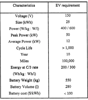
1-2 USABC battery goals for electric vehicle
1-3 Structures o f potential host polymers for electrolytes
1-4 The surface films developed on lithium in several different battery liquid electrolytes
3-1 The observed critical current and the diffusion coefficient o f P E 0 gLiC104.
3-2 Variation o f the critical current and apparent conductivity with cycle number obtained with P E 0 gLiC104
3-3 Measured and derived quantities for the cell: L i/P E 0gLiCF3S 0 3/Ni
3-4 The effect o f temperature on the conductivity o f P E 0 gLiCF3S 0 3,
3-5 Variation o f the critical current and apparent conductivity with cycle number obtained with P E 0 gLiCF3S 0 3
ACKNOWLEDGEMENT
This project was sponsored by H ANKOOK TIRE Mfg.Co.Ltd. The author would like to express his sincere thanks to Professor D.E.Williams for his encouragement and guidance and w ithout whom, this work could not have been completed. Thanks are due to M r.Dave Knapp and the staff in the mechanical workshop who were already ready to give advice and help.
&£\°\
7|2jt|-£pL 0|A H te l# 5£KH1^§|2| SL-E E # 011711 ^ = ^ j u | c h o j A ^ h 0 |£ H ^ . 2 .^ 7 ) [ X \ ^ 0 ^ 9 1 0 1 U|| Ei £ |-Oj
^ y o l | 7 l l C K IO H - 7 ^ 0 1 D^ | S f j - q c K £ £ °h t ^ a ^ a ^ o i i 7i|A|
2.7S\\^ £ | * H - y S - y o | | 7 l | S . ^ A ^ U M C K A i O l | 7 l | ^ I j O l E l O l ^
E t S O | H u lE |^ C ||7 ; |- * | o m & t : El-01ol g
^ l £ ] 2 | £ 7 | £ 7 1 | £ ^ = 1 1 - 1 ^ . 4 ^ 7 ^ 0 1 E § # *
a n y 31- n 7 ^ # f i | c c ^ l h S £ ojtci # # ^ < ^ j L . | c K
XII7 1- S i 7 | ; ; ^ l A H f o g 7 H # o i | 7 | | E g ^ j # # o h £
s a i l * I s a ^ M E h 0 | X | | a # s | a h # f t q c K o j E ^
CHAPTER 1.
CHAPTER 1. Introduction
1.1. Lithium Polymer electrolyte Batteries fLPB)
1.1.1. Background on Lithium Batteries
Lithium ambient temperature batteries represent one o f the very active
relatively new fields in battery technology. Primary (disposable) batteries based
on lithium anodes have been developed during the past 20 years and large
numbers o f systems are presently in commercial production. These include
batteries for pacemakers such as the lithium /iodine couple ( L i/y [1], thionyl
chloride batteries (Li/SOCl2) for military uses and uninterruptible power supplies
[2], and lithium manganese dioxide batteries (L i/M n 0 2) for cameras and memory
back-up [3]. There are beneficial advantages to a lithium anode battery such as
high energy density, high voltage and low self-discharge. The specific energy and
volum etric energy density o f lithium-thionyl chloride cells are 500 Wh.kg'1 and
1000 W h.dm'3 at low-rate small cell, w hich is among the highest o f all practical
battery system [2], The electrode reactions are shown in table 1-1.
System Overall reaction
Li/SOCl2 4 Li + 2 SOCl2-> 4 LiC l+S+S02
L i/M n 0 2 MnIV0 2 + Li -> M nm0 2 (Li")
Li/CFX xLi + CFx —» jcLiF + C
L i/S 0 2 2 Li + 2 S 0 2 —^ Li2S20 4'l'
Table 1-1. The overall reaction in lithium primary batteries
Secondary (rechargeable) lithium batteries have made no significant impact
on the market because rechargeable organic electrolyte cells with metallic lithium
anodes have many critical problems, most notably po o r safety which limits their
size to smaller cells. The most commonly used lithium source is lithium metal
foil. It is a lightweight material, which has many o f the desired characteristics
needed for a high energy and high pow er battery. However, the relatively poor
cycling efficiency o f the lithium anode arises because it is not thermodynamically
stable in typical non-aqueous electrolytes. Cells contain typically a three to five
fold excess o f lithium in order to ensure a reasonable cycle life. Lithium plating
and stripping during the charge and discharge cycles creates a porous deposit o f
high surface area and increased reactivity o f the lithium metal with respect to the
electrolyte. The reaction is highly exothermic and can lead to venting with flame
The reaction can be alleviated or reduced by the use o f alternative anodes that
undergo displacement or insertion reactions at activities less than unity. Concerns
about safety, due to the low melting tem perature and high reactivity o f lithium
with most liquid electrolytes, led to the investigation o f lithium alloys as possible
negative electrode [4], The high melting point o f the alloy offers a safety
advantage over pure lithium since cells could withstand larger temperature
excursions. However, the use o f lithium alloys in ambient temperature batteries
resulted in a dramatic decrease in cell capacity due to poor anode utilization at
high current densities.
More recently, graphite carbons have been evaluated as negative electrodes
because they could provide chemical stability, improved cycle life and safety [5],
The disadvantage is a decrease in the energy density compared to that o f a pure
lithium anode cell. Also, another main drawback, at this time, with LixC
composite negative electrodes is the com plex processes needed to produce
graphite carbons with desirable properties. Lithium n-doped conjugated
conducting polymeric materials have been used as anode [6], The use o f these
polymeric materials as compared to pure lithium provided various disadvantages
such as lowering o f the cell voltage and gravim etric energy density.
Conventional organic electrolytes have the high ionic conductivities required
for designing high power batteries for electric vehicle applications. Unfortunately,
unwanted reactions cause premature cell failure. During charging/discharging
cycling, electrolyte decomposition takes place and the decomposition products
appear to react with the polymer separator. Deterioration o f the separator can
cause cell failure due to internal shorts. Ion-conductive solid polymer electrolytes
have been proposed to alleviate these problems. Significant research activities to
produce highly ionically conductive solid polym er electrolytes are being carried
out. These solid polymer electrolytes are electrical insulators and therefore, the
use o f a separator film is not needed.
1.1.2. Lithium polymer electrolyte batteries
It is generally believed that solid polymer electrolyte cells will be considerably
safer than liquid electrolyte cells. This may be due to the relatively slower
reaction rate between lithium metal and the polym er electrolyte with reduced
mass transport in the polymer electrolyte. Since the concept o f such a battery,
based on the use o f poly (ethylene oxide)-lithium salt complexes was first
discussed [7], their development has focused largely on rechargeable systems
utilizing insertion/intercalation cathodes in conjunction with metallic lithium
anode.
The concept o f the rechargeable, solid electrolyte battery is based on two
discharging, the other as a corresponding sink. The two electrodes are separated
by a thin-film polymer electrolyte acting as a lithium-ion carrier. This technology
combines the use of a thin-film electrolyte with lithium reversible electrodes. The
most thoroughly studied general configuration o f polymer electrolyte cell is
shown schematically in figure 1-1.
Figure 1-1. C onfiguration of polym er electrolyte cell
In polymer electrolyte systems, the most commonly used lithium source is
lithium metal foil. The cathode compartment o f the practical lithium-polymer
electrolyte battery (LPB) is a composite o f a lithium sink, a suitable electronic
conductor, and the polymer material used in the electrolyte. The lithium sink in
the composite cathode comprises Li+ ion insertion compounds including TiS2,
V60 13, Mo0 2, [8,9,10], M n 0 2, FeS2 and FeS have been studied in primary
systems [11]. P-doped conducting polymers have been used as cathode since
electrical conductivities similar to metals. Unfortunately these polymers are heat
and air sensitive and, as a result, the desirable electrical properties deteriorated
w ith time [12].
The most widely studied polymeric electrolytes are those based on poly
(ethylene oxide) and other modified-polyethers which are readily soluble in
common solvents (e.g., alcohol and acetonitrile). Consequently, simple
continuous solution casting techniques have been developed for the fabrication o f
large area membranes. Doping o f the film w ith an appropriate lithium salt is
carried out prior to casting in a suitable co-solvent. Polymer films with initially
poor mechanical properties may be improved by cross-linking using irradiation
technique.
Despite the fact that the organic and the solid state technology are capable o f
using the same electrode materials, there are major advantages in favor o f the
solid state system [13,14],
(1) lower material cost and manufacturing cost due to ease o f assembly and high
automation potential
(2) Cell component compatibility and battery safety
(3) Low electrode surface loading and low current densities
(4) Thin homogeneous separator to avoid Li dendrites
1.1.3. A pplication in electric vehicles
During the past two decades, rechargeable lithium batteries using metallic
lithium and polymeric electrolytes have been touted as a possible solution to the
electric vehicle (EV) battery problem. The effort to bring advanced batteries for
electric vehicles has been undertaken by the United States Advanced Battery
Consortium (USABC) whose members include Ford, Chrysler, GM, the
Department o f Energy and battery companies. The USABC has established a
time line that includes goals for battery development.
Characteristics EV requirement
Voltage (V) 150
Size (kWh) 25
Power (W /k g : W/l) 400 / 600
Peak Power (kW) 50
Average Pow er (kW) 12
Cycle Life > 1,000
Year 10
Miles 100,000
Energy at C/3 rate 200 / 300
(W h /k g : Wh/1)
Battery W eight (kg) 550
Battery Volume (1) 280
Battery cost ($/kWh) < 1 00
Lithium batteries are currently being studied to meet the USABC goals.
These include lithium-ion and lithium -polymer batteries. Although the lithium-
ion battery consisting o f intercalation/insertion compounds as electrodes and
organic electrolytes is being studied for electric vehicle, the disadvantages o f this
system are its very high cost and the ventilation system required to keep the
batteries cool. The manufacturing costs are high because o f a highly purified
organic material for electrolyte and a complex cell control system. The lithium-
polymer electrolyte battery is expected to cost 20% more than lead-acid battery
but deliver twice the energy because much higher voltage would be achieved with
lithium and lithium is much lighter in weight than lead.
1.2. Polymer electrolyte
In 1978 it was proposed that the complexes o f poly (ethylene oxide) with alkali
metal salts may be prove to be good solid-state electrolytes [7]. They are, in
principle, compatible with the insertion compounds used as cathode. The
potential difficulty for an all-solid-state battery is that the process o f intercalation
o f lithium into a cathode material is accompanied by a volume change, which
cycles during battery cycling. In the case o f V60 13, lithium is inserted into
intercalate host material, V60 13 to form insertion or intercalation compounds on
X L i + V 60 ,3 - > L i^ V jO u , 0 < a : < 7.9 ...(1.1)
At this stage, there is an increase in volume o f the intercalation compounds
and a resulting decrease in volume o f the electrolyte. This process is reversed on
charging. Whilst volume change is not a significant problem with batteries
incorporating liquid electrolytes, it may cause a serious problem with solid-state
batteries, leading to poor contact between the electrode and the electrolyte.
However, since the elasticity o f the polymer could accommodate volume changes
on intercalation and maintain contact with the electrode on repeated cycling, a
polymer electrolyte seems a good candidate for solid-state battery electrolyte.
1.2.1. Polymers
The most commonly used polymer matrix for electrolytes is poly (ethylene
oxide) (PEO). The polymeric derivatives o f ethylene oxide are divided into two
classes, which are defined by molecular weight. Low molecular weight polymers
with an average molecular weight of 200 ~ 20,000 are called poly (ethylene
glycol)(PEG) and high molecular weight o f lxlO 5 ~ 5xl06 are called poly
and the trademark Polyox™. The presence o f the ether linkages is responsible for the unique properties o f this polymer. The carbon-oxygen bond of ether is
stronger than the carbon-carbon bond o f a hydrocarbon with bond energy o f 84.0
k c alm o l'1 and 83.1 kcalm ol'1, respectively [15]. The barrier to rotation around a
carbon-carbon bond in a hydrocarbon is about 3 kcal-mol'1, whereas the barrier to
rotation around the carbon-oxygen bond o f an aliphatic ether is only about 1.2
kcal-mol'1 [15], The presence o f the electron-rich oxygen atoms in the backbone
structure o f the polymers offers a site to form complexes with alkali metals.
Poly (propylene oxide) (repeating unit (-C H 2-C H C H 3- 0 - ) (PPO) has been studied as the polymeric matrix for electrolytes [16], It was expected that electron
density o f oxygen atom in poly (propylene oxide) would be increased due to the
secondary carbon atom. However it showed m uch less solvating property than
poly (ethylene oxide). This can be attributed to the steric hindrance by the methyl
group.
It was recognized that the most important requirement o f suitable polymer
hosts was segmental motion o f the polymer backbone, and that the ionic motion
depended to a large extent on flexibility o f polym er backbone [17], Network
electrolytes were studied under the assumption th at these polymers could keep as
much o f the amorphous regions as possible, since the crystalline phase has been
shown to be non-conductive. Poly (ethylene oxide) cross-linked by irradiation or
the amorphous content o f polymer electrolytes consists o f attaching short chain
polyethers to inert polymer backbones. Poly (bis-(methoxy ethoxy ethoxy)
phosphazene) (MEEP) has been one o f the m ost successful polymer electrolytes
[
20
],
(OCH2CH2-)-O C H 3
MEEP (n=2)
— [-N=P-]„—
( 6
c h2
c h2- ) -
o c h3
Electrolytes based on several other polymers have been the subject o f some
studies and these polymers are listed in table 1-3.
Polymer Repeat Unit
Polyepichlorohydrin ( O C H 2^ H )
-c h7c i
Poly(ethylene succinate) [ 0 ( C H 2)20< ^(C H 2)2 C ]
-0 0
Poly(ethylene imine)
- (-C H 2CH2N H
-)-Poly(alkylene sulfide)s
(n-2~6) [ ( C H 2)n S ]
1.2.2. C onduction in polym er electrolytes
The conductivity o f most inorganic solid electrolytes and crystalline polymer
electrolyte follows an Arrhenius equation:
a = A •T"1/2 exp (-E a / kT).. .(1-2)
where E a is the thermal activation energy and A denotes a pre-exponential factor,
which includes the carrier concentration. In the early studies o f PEO-salt
complexes, it was suggested that cation hopping through the helices o f the
polyethers chain could be the mechanism for ion transport [21]. This
interpretation showed a good agreement with Arrhenius behavior. However, this
interpretation is no longer accepted.
A very important insight into the conduction mechanism in polymer
electrolytes has been that the ions in the amorphous phases, not those in the
crystalline phases, are responsible for the ionic conductivity o f polymer
electrolytes [22]. The well-known V o g el-T am m an -F u lch er (VTF) equation has
been used to describe ion transport in polym er electrolytes. This equation showed
a good agreement with the observed non-linear relationship between log
(a)
vs.CT = o 0exp [-B /(T -T „)].
..(1-3)where
B
is an apparent activation energy andTa
is a fitting parameter which canbe referred to as the zero mobility tem perature or ideal glass transition
temperature.
When
T-T„ = T,
the VFT equation becomes identical to Arrhenius equation.Also the VFT equation indicates that the higher conductivity can be achieved by
reducing in the glass transition tem perature,
Tg.
For high molecular weight poly (ethylene oxide), two or more phases may
coexist. Poly (ethylene oxide) is a semi-crystalline solid composed o f two phases
at ambient temperature, one o f the phase o f being amorphous and the other
crystalline. The same is true o f polym er electrolytes based on poly (ethylene
oxide). Below the melting point o f pure crystalline poly (ethylene oxide), the
conductivity is dominated by the ions in the dispersed amorphous regions and
follows Arrhenius behavior showing linear log <r vs. 1/T. As the temperature is
raised, it causes an increase in mobility o f polym er chains. This results in an
increase o f the ionic conductivity. W hen the temperature is high enough that the
salt-rich crystalline complex dissolves in the amorphous phase, the number o f
charge carriers is increased. Therefore, the ionic conductivity is increased further.
Since
Tg
o f the polymer electrolytes is also affected to a large extent by theshould be considered. The effect on conductivity on increasing salt concentration
in the amorphous region is clearly observed as an increase in the ionic
conductivity. However, as salt is added further, the polymer-salt complex
becomes more rigid due to a decrease in polymer flexibility. This is reflected by
an increase in
Tg.
This indicates that the conductivity has a maximum valueaccording to the concentration o f salt in polymer electrolytes.
1.2.3. Salt effect on the conductivity; LiC104 versus LiCF3S 0 3
The technology for solid state lithium batteries is a very recent development
and improvements and modifications are being made continuously. The initial
cell configuration was based on the sulfonate-based complex (PE0-LiCF
3
S 0 3).An example o f cell optimization is the introduction o f another electrolyte - the
perchlorate-based complex (PEO- LiC104) to improve the ionic conductivity and
hence cell performance. It has been generally known that the sulphonate-based
complex has some disadvantages compared to the perchlorate-based complex.
The perchlorate-based complex has a higher conductivity (2 x 1CT
4
S/cm vs. 2 x10
'5
S/cm at 100°C) than the sulphonate-based complex. But the perchlorate-based complex has lower cation transport number and is more difficult to handle
because o f hygroscopicity [24].
crystalline complex, which does not becom e amorphous until above 120°C [25],
From observations under polarized light, it has been found that the sulfonate-
based complex films are spherulitic in nature below 120°C. In polymer
morphology, crystallites are often arranged in larger aggregates known as
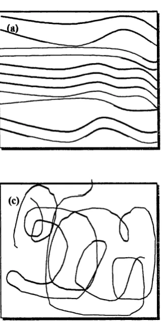
spherulites. Figure 1-2 shows how the polym er chains are thought to be arranged
in the spherulites. Large spherulites contribute to stiffness in polymers resulting
in a decrease in mobility o f ions through polym er electrolytes. This is reflected in
a decrease in conductivity. The structures obtained in recent diffraction studies on
the sulfonate-based complex indicated that the triflate anions orient around
helical polymer chains and direct the chain packing [26],
■— ■— ' 'X
Figure 1-2.
(a) Crystalline, (b) spherulitic,
and (c) amorphous regions
Based on the literature, the mobility o f the anion correlates linearly with the
reciprocal o f square root o f formula weight, the mobility o f C I0 4* anion be higher
than that o f CF
3
S 0 3' anion. This was assumed due to a higher tendency o fC F
3
S 0 3" anion over C I0 4_ anion to associate in complexes [28], In turn, thecation-polymer interaction becomes weakened as a result o f strong ion
association. The migration o f anions makes a contribution to the electrical
conductivity.
P E 0 -L iC F
3
S 03
based polymer electrolytes may contain more semicrystalline pure PEO regions than P E 0 -L iC 1 0
4
so that its arrangement becomesmore spherulitic below 120°C compared to P E 0 -L iC 1 0
4
based polymerelectrolytes. Thus the use o f (PEO )-L iC F
3
SC>3
complex results in reducing ionicconductivity below 120°C. The P E 0 -L iC 1 0
4
complex is known as being asuperior ionic conductor since it contains larger amorphous regions at all
temperatures above 60°C. Thus it has a far better rate-performance.
The thermal history o f the PEO complex is an important factor in determining
the degree o f crystallinity and, hence, the conductivity. The P E 0 -L iC F
3
S 03
electrolytes have fast recrystallization kinetics, i.e., the formation o f the various
crystalline phases occurs within minutes o f the film reaching room temperature.
This may have a negative effect on the cell assembly process since a thermal
lamination process is the essential cell assembly process for lithium polymer
1.3. Lithium Passivation
Lithium is the most promising material for use as the anode o f high potential
and high energy density rechargeable batteries. However, the problem with the
lithium negative electrode in conjunction with liquid electrolytes is the
irreversible capacity loss that occurs during cycling. This irreversible capacity
loss has been related both to the reaction o f lithium with all the species in the
electrolyte solutions, because o f its high chemical reactivity. Organic solvents
such as propylene carbonate (PC) and butytolactone are non-volatile, polar and
highly conductive and these are usually used as electrolyte solvent. However,
they are too reactive toward metallic lithium. The formation o f a passivating film
causes loss o f active lithium during the cycling. Therefore, the search for
solvent-electrolyte combinations for high perform ance lithium rechargeable
batteries continues still.
1.3.1. Lithium passivation in liquid electrolytes
The surface film formed on lithium anodes in carbonate-based electrolyte
solution has been extensively studied by FT -IR and impedance spectroscopy. The
composition o f surface films and interfacial properties in relation to the cycling
propylene carbonate (PC) were identified to contain mostly Li-alkyl carbonate
(R 0 C 0 2Li). However, when the electrolyte contained impurities such as water
and C 0 2, the surface films contained more types o f surface species (e.g., Li2C 0 3
and R 0 C 0 2Li). In tetrahydrofuran (C4H 80 , THF)-based solution, Li-alkoxide
(ROLi) was found. When the passivating films forms during the cycling, lithium
ions must be transferred through these films. The electrochemical behavior of
lithium in an electrolyte is surface controlled. If the passivating films formed is
not uniform in composition, porosity or thickness, this may lead to less uniform
Li transfer through the passivation layer. Hence, lithium deposition and
dissolution is likely to be irregular and non-uniform, leading to dendritic growth.
Dendrites are easily inactivated due to high surface area for the reaction with an
electrolyte. These are easily disconnected from the electrode, which leads to
lower cycling efficiency. For a similar reason, a uniform deposit is less likely to
Passivating films
Figure 1-3. The irreversible capacity loss m echanism showing the effect of deposit morphology on the form ation of the passivating film by generating
high surface area (l:Iess uniform ,
2
:uniform deposit)The electrical properties o f the Li-solution interface formed in the different
salt solution are remarkably dependent upon the nature of the solution.
Consequently, the morphology and Li utilisation in repeated charge-discharge
cycling is also influenced.
For example, the morphology o f the lithium deposited had the typical dendritic
form in LiC104-PC, while suppression o f lithium dendrites had been observed in
LiAsFg/2-MeTHF. Table 1.4 gives a summary o f the present understanding o f the
Electrolytes Component of surface films Reference
LiAlCl4-SOCl2 LiCl [33]
Li2S20 4 [33]
LiBr-SOj
Li2S 0 3, Li2Sx0 3,LiS20 3 [34] LijCOj
Polymer [33]
LiC104-PC CH2CHCH20 C 0 2Li, CH3C H C H 0C 02Li [35]
CH2CH2CH2OCQ2Li, [36]
(CH2CHCH20 C 0 2Li)2
LiC104-D 0L Li20 [37]
LiC104-THF Polymer [33]
LiAsF6- -(O-As-O-)R [38]
2MeTHF As(OR)xF„, (n=3,6) [39]
PC : propylene carbonate, DOL : dioxolane, TOT : tetrahydrofiiran,
2M eT H F : 2-methyl tetrahydrofuran
1.3.2. Dendrite growth in liquid electrolytes
There has been quite a lot o f work done on electrochemical deposition o f the
lithium in organic electrolytes. One o f the most serious problems in lithium
secondary cells is dendritic growth o f lithium deposits. As mentioned above, the
morphology o f the lithium deposited is dependent on the nature and composition
o f electrolytes that are used in electrochemical systems and the nature o f the
passive layer developed on lithium is dependent on the electrolyte.
If one considers the ideal electrochemical deposition process macroscopically,
the first step would be the formation o f stable nuclei on a smooth and defect free
surface. Once stable nuclei have been formed, their subsequent growth might
change the local conduction and therefore the local rate o f growth. The evolving
shape o f the nuclei might thereby be changed as they grow. The rate o f deposition
o f metal ions, therefore the rate o f reduction, depends on the electron transfer
process at the interface and on the rate o f mass transport o f ions through the
electrolyte. Hence, a local increase in the rate o f growth following the initial
deposition process could be caused by the concentration o f the applied electric
field on the nuclei and by a change in diffusion geometry.
The applied electric field is concentrated more at the surface o f a protruding
crystal than at the flat electrode surface. The diffusion distance for metal ions to
move to the electrode becomes shorter to a growing center than to a flat electrode
increase further because the nuclei formed on the electrode increase the area
available for further reduction.
As the individual nuclei with different sizes grow further, the distance between
neighboring nuclei gets closer. Overlap between neighboring nuclei will occur.
The rate o f deposition will increase less rapidly than previously. When overlap o f
neighboring nuclei has occurred over the whole surface and been completed, the
deposit layer will thicken as deposition continues over the total area o f the
substrate. This is the ideal case for an electrochemical deposition process.
However, when the deposition conditions around the nuclei have been
changed enough as a consequence o f their growth, the deposition process shows
irregular behavior. The state o f the electrode surface must be considered carefully
since the interfacial reduction mechanism can be modified by the state o f the
electrode surface. Based on the results from literature sources [40,41], when low
overpotential is caused by low interfacial resistance, homogeneous and compact
deposits have been observed. W hen high overpotential is caused by high
interfacial resistance at the electrode, dendritic and non-homogeneous deposits
are observed. Hence these results indicate that the instability in growth producing
dendrites has a close relation with the growth o f the passive films on the electrode
surface, which increase the electrical resistance.
density. The deposition current density (i) is applied on the clean and defect-free
electrode surface (fig. 1.4a).
(a) A clean electrode surface
C u rre n t density,
i
Electrode
(b) An electrode surface with the passive layer
C u rren t density, i
r 'i
r
i
r
i
iijjljjjijjlyjeiij
r
Passive
layer - II
Elec
. . ■trode
Figure 1.4. A schematic presentation of the concentrated current density on
However, if due to unidentified reasons resistive layers have been formed on
the electrode surface, the applied current density will concentrate on the clean
part o f the surface (fig. 1.4(b)). The clean part o f the electrode surface will
experience a higher current density than previously. At this part o f the electrode,
the deposition would become much faster and in the extreme case, dendrites
could occur. Hence, the growth o f deposits would be controlled by the nature o f
the passive layer, particularly by the electrical resistance o f the passive layer.
1.3.3. Effect of the deposit morphology on battery performance
An electric current flowing in a galvanic cell is usually distributed uniformly
over the whole surface o f the electrodes. Ideally, the current density should be the
same at any point o f the surface. However, non-uniform distribution is possible if
different segments of the surface are not equally accessible to the current. There
are a few factors that determine the actual distribution o f current density. The
passive and native film layers on the electrode can control the actual distribution
o f current density.
The composition and morphology o f the surface film layer are therefore
important in determining the distribution o f current density. I f the surface layer
density distribution becomes profound. In terms o f ionic movement through the
surface layer, a porous surface film is more favorable than a dense film. The
composition and morphology o f the surface film layer depend on the nature o f the
electrolyte used in the system and the effect o f the surface film layer on the
electrochemical behavior also depends upon the cell operation conditions (e.g.,
discharge-charge current densities). Recently, much w ork has been performed to
investigate the nature and composition o f the passive film at the lithium negative
electrode-organic electrolyte interface [39,42,43] (see Table 1.4.) and native film
at the commercially available lithium [44], XPS analysis identified the native film
found on the as-supplied Li metal and suggested that it probably comprised Li
2
0 ,LiOH and Li
2
C 0 3.Native surface films on a lithium electrode could produce an uneven
resistance distribution at the surface since those films consist o f many compounds.
I f the current were not sufficient enough for Li to dissolve from all parts o f the
lithium electrode, the applied current for deposition o f lithium would be focused
in the relatively low resistance part o f the lithium electrode even at the very initial
stage o f Li deposition. This idea supports an advantage o f high rate discharge in
the practical cell because high rate o f discharge can reduce the localization o f
current during discharging.
Much work on the deposition process in lithium/organic electrolyte systems
growth o f the Li nuclei, irregular growth even fractal growth has been observed
on the lithium negative electrode in organic electrolyte systems.
It is known that the cycleability o f lithium secondary batteries employing a
lithium metal negative electrode and organic electrolytes depends on both charge
and discharge current densities. M uch w ork has been done concerning the cycle
life and lithium deposition morphology dependence on charge and discharge
current densities. It has been demonstrated that cycle life decreases with increase
in discharge current [42]. A cycle life dependence on charging current density has
also been reported in Li/M oS
2
and Li/Li0
3
M nOy cells [43,45,46,47],The cycle life dependence on charge/discharge current densities can be
explained by the morphology o f Li deposited. It has been reported that two types
o f Li deposit are observed from organic electrolytes [48], These were needle-like
Li and particle-like Li. The needle-like Li was thought to be ‘dead lithium ‘ since
it remained on the electrodes after anodic dissolution. This lead to a decrease in
the amount o f needle-like lithium during charge-discharge cycles, thus eventually
resulting in cycle life decrease.
According to the literature [48], Li deposition starts with needle-like Li, with
particle-like Li subsequently growing at the top. In the dissolution process, the
particle-like Li dissolves first followed by dissolution o f needle-like Li, as
(a) at charge: Needle-like Li -*■ Particle-like Li
i l i l A
-(b) at discharge: Particle-like Li -*• Needle-like Li
Figure 1.5. Proposed mechanism of the formation of particle-like Li during discharging and the formation of needle-like Li during charging from
ref
[48],
During the following charging process, the current will be focused at the
point from which the Li was deposited during discharging. Since the fresh Li
deposited on an inert cathode is more reactive than original lithium anode with
native surface films, side reactions betw een the Li deposited and impurities
and/or electrolyte could occur. Any newly formed passive film on the freshly
deposited Li would play the same role as the native film. Any such passive layer
resulting in the localization o f current density. The actual current density would
be higher than the applied charging current density. This actual charging current
density would be much higher on the needle-like Li deposits than on the particle-
like Li deposits. The formation o f the passive layer on the deposited Li surface
may be accelerated at the needle-like Li surface. During discharge-charge cycles,
needle-like Li produces electrochemically inactive lithium referred to as ‘dead
lithium ’. This ‘dead lithium’ is one o f the commonly observed failure modes
from the cell at the end o f service. M uch w ork has been directed at explaining the
formation o f an electrochemically inactive ‘dead lithium’ through the needle-like
(dendritic deposit). One proposal is that electrochemically active lithium reacts
w ith electrolytes (and/or impurities) to form needle-like lithium. Needle-like
lithium can be easily passivated and finally disconnected from the electrode [49],
Also it has been proposed that metallic lithium can become isolated within
passivating layers and that this leads to electrical isolation o f the deposited
lithium [48], Accordingly, it has been suggested that needle-like Li leads to a
cycle life decrease. This proposed mechanism suggests that the cycle life
dependence on both charge and discharge current densities can be explained by
morphological changes in the lithium anode and hence suggests the morphology
o f the Li deposited is an important factor determining the useful cycle life o f
lithium secondary batteries.
electrolyte that is used in the battery system. Needle-like Li is typically observed
from the lithium cell in propylene carbonate (PC) containing 1.0 mol/dm
3
LiC104,whilst in propylene carbonate (PC) containing 5x1 O
'3
mol/dm3
HF, the lithiumdeposited has a hemispherical form with no irregular shapes [50], It has been
argued that the addition o f a small amount o f HF to the electrolyte is effective in
suppressing to the lithium dendrite formation by forming a uniform layer on the
electrode. This uniform layer on the electrode is expected to make the current
distribution uniform.
As a general summary, factors causing the reduction in cycle life o f a lithium
electrode in organic electrolytes are:
(i) existence o f native film passive layer formation leading to an increase in cell
impedance
(ii) needle-like Li deposition resulting in the formation o f electrochemically
inactive
‘dead lithium
’during cycling.
And these two factors are closely related w ith each other.
1.3.4. Lithium passivation in hybrid polymer electrolytes
Polymer electrolytes can be typically divided into tw o types. The first having
conductivities ranging 10‘
3
~1(T* S/cm at 100°C, comprises polymer electrolytespoly(ethylene oxide) (PEO)) and lithium salts. The other comprises hybrid
polymer electrolytes formed by the addition o f plasticizers such as propylene
carbonate (PC) and ethylene carbonate (EC) to common polymer electrolytes in
order to increase conductivities at room tem perature [51].
While there is much information on the nature and composition o f the passive
film formed at the Li electrode in organic electrolytes, little information is
available on the composition and morphology o f the passive film and its effect on
the electrochemical behavior o f polymer electrolyte systems. It has been reported
that a polyacrylonitrile (PAN) based hybrid polym er electrolyte with the addition
o f propylene carbonate (PC) and ethylene carbonate (EC) shows a similar
electrochemical behavior at the interface to that found in organic electrolyte
systems [52]. The hybrid polymer electrolyte reacts with the lithium negative
electrode. The accumulation o f reaction products at the interface results in a
passive surface layer. This is reflected in the interfacial resistance increasing
continuously as a function o f time. Polar solvents added as plasticizers to the
polymer complex react with the lithium metal to form the passive layer, not a
polymer matrix (in this case polyacrylonitrile (PAN)) since polar solvents are
more likely to react with lithium than polymer matrix.
In terms o f the morphology o f the lithium deposited, the growth o f dendrites
in secondary cells employing polymer electrolytes has been considered as less
solvents are added to the polymer complex, the resulting morphology is
dependent on the amount o f the added organic plasticizer. This means there might
be an optimized ratio o f polymer matrix to liquid electrolyte and salt
concentration to secure the ionic conductivity and the favorable morphology at
the same time.
Based on the literature [40,41], dendritic growth might be expected when a
high overpotential is developed at the interface. The high overpotential reflects
the high resistance at the interface. In hybrid polym er electrolytes containing both
liquid solvents and solid polymer, the polymer raises the resistance in electrolytes.
It might be expected that the higher the proportion o f polymer, the higher the
resistance o f electrolytes. In terms o f the ionic conductivity o f polymer
electrolytes, polymer matrices having lower glass transition temperatures (7^)
should be favorable since the most important factor in determining glass
transition temperature (
T
g) is the flexibility o f polym er chains in a medium. Asthe weight ratio o f host polymer to liquid solvent increases, the flexibility o f
polymer electrolytes will be decreased. This also results in the decrease in ionic
conductivity. So, following the simple argum ent above, the likelihood o f
formation o f Li dendrites should be increased. However, the result from the
morphology observation in hybrid polymer electrolytes has been against this
expectation [52], As the weight ratio o f host polymer to liquid solvent increased,
Based on the results, the effect o f host polym er on suppression o f lithium
dendrites can be explained as follows: when deposits grow at the electrode
surface, initially they will experience similar conditions to lithium deposits in
organic electrolytes. As lithium deposits grow further, they will encounter the
stiff phase o f polymer. Accordingly, a fractal grow th leading to dendrite
formation will be suppressed.
1.3.5. Lithium passivation in high-temperature polymer electrolytes
It was thought that polymeric electrolytes would provide better chemical and
electrochemical stability toward metallic lithium than the liquid electrolyte
systems. However, it has been shown by impedance spectroscopy that a
passivating film layer forms at the L i/P E 0 gL iC F
3
S 03
interface after aging at theelevated temperature corresponding to the nom inal operating condition [53]. An
increase in interfacial resistance (/?,) to a steady value with storage time and
temperature was observed. A linear dependence o f the interfacial resistance as a
function o f temperature [(l//?i) vs. 1/T] was observed and it was assumed that
1/Ri
reflected the ionic conductivity o f the passive film. The behavior wasinterpreted as being indicative o f the form ation and growth o f passive films on
the lithium electrode surface. According to this literature, the formation o f the
passivating films is not simply caused by the reaction o f water or oxygen with
concentration o f LiCF
3
S 0 3, in reactions which were likely to occursimultaneously and competitively with the reaction o f water or oxygen and with
the electrochemical reaction. This assumption was based on the interpretation o f
the cyclic voltammetric study o f P E
04
5
LiCF3
S0 3
. A reduction process occurringprior to the deposition o f lithium was interpreted as the reduction o f CF
3
S 0 3"anion [54],
LT+ CF*S<V+ «r ^ LiF+»CF^SOi"..(i-4)
Passivating film formation at the interface between lithium electrode and
PEO-based electrolytes has been reported though without any clear identification
o f the nature o f the films [55,56]. However, recently clear evidence by FT-IR
spectroscopy o f the nature o f the passivating film formed in PE0-LiC 10
4
electrolyte has been presented [57], Lithium alkoxide was detected as a side
product, assumed generated through the reaction between the freshly deposited
lithium and polymer matrix, PEO. The cleavage o f ether-type C -0 bond to form
alkoxide functionalities was suggested. A similar reaction mechanism was
proposed for the reaction between lithium and ether-based electrolytes (dimethyl
ether (DME), tetrahydrofuran (THF)). [58], Electron transfer from lithium to a
solvent molecule could form a radical anion, which is stabilized by a Li+ cation.
[R -0-C H 2-] + Li+ + e" -> [R -0 -C H 2- ] » Li+
—> —>
[R-0"Li+]+ other products
Another example showing degradation o f polym er matrix to form a thin
passivating film at lithium/electrolyte interface was reported. When the polymer
electrolyte plasma-polymerized tris (2-methoxyethoxy) vinylsilane with LiC104,
was used, the formation o f a resistive layer consisting o f a mixture o f lithium
alkoxide and lithium alkylsilanolates was identified by FT-IR measurement [59]
The degradation scheme o f polymer matrix was proposed as given below.
o c h
2
c h2
o c h3
o c h2
c h2
o c h3
-Si-OCH2CH2OCH3 -> [-Si-O CH 2CH2OCH3 ]“’ Li+
OCH2CH2OCH3
OCH2CH2OCH3
(a) =>
-Si-O L i + •CH2CH2OCH3 -> CH3CH
jOCH3 t
(b) => -Si-OCH2CH2OLi + »CH3 -> CH41
(c) =>
-|i-O C H 2CH2OLi -> -S i-O L i + • CH2CH2OLi
Generally, a polymer is characterized by a molecular-weight distribution,
which is entirely controlled by polymerization method. Commercially available
poly (ethylene oxide) is mixture o f chains o f different lengths. Also, poly
(ethylene oxide) contains some additives. Anti-oxidants such as
2
-propanol(CH
3
CHOHCH3
), ethanol (CH3
CH2
OH) are added to prevent degradation ofpolymer. It has been suggested that these low-molecular-weight compounds
could react with lithium to form the passivating films. However, an electrolyte
employing a highly pure PEO did not provide any significant amelioration o f the
formation o f the passivating film [60].
1.4. The objectives of the project
It is clear from the above considerations that the major drawback to
commercialization o f lithium rechargeable batteries based on polymer
electrolytes is the performance limitation caused by the passivating films during
cycling. However, there is a need for more detailed understanding o f the nature o f
these passivating films and their effect on battery performance. The objectives o f
this project can be summarized as:
1. Identification o f the possible reactions that form the passivating films;
electrolyte cell;
3. The effect o f the passivating films on the deposition morphology o f lithium and change in morphology during cycling;
4. Investigation o f the relation between the deposition morphology and cycling efficiency;
References
1. J. Johnson and D.Schrodt, in “
Modem
Battery Technology
” Ed. Clive.D.S.Tuck, Ellis Horwood, NewYork, (1991), pp.365-3832. H.F.Gibbard and T.B.Reddy, in
“Modern Battery Technology
” Ed. Clive.D.S.Tuck, Ellis Horwood, NewYork, (1991), pp.287-3123. S.Narukawa and N.Furukawa, in
“Modern Battery Technology
” Ed. Clive.D.S.Tuck, Ellis Horwood, NewYork, (1991), pp.348-3654. A.Belanger and M.Robitaille,
US Pat.
4,652,506 (1987)5. P.Touzain and RYazam i,
J.Power Sources
, 9 (1983) 3656
. T.Nagatomo,J.Electrochem.Soc.,
134 (1987) 3057. M.B.Armand,J.M.Chabagno and M .J.Duclot, in
“Fast Ion Transport in
Solids'
’ , Ed. P. Vashishta, North Holland, N ew York, (1979) p. 1318
. M.Gauthier,J.Power Sources
, 14 (1985) 239. K.West, T.Jacobson and S.Altung,
J.Power Sources,
14 (1985) 1210. M.Gautheir, 1st International Symposium on Polym er Electrolytes, St. Andrews, Scotland, June 1987
11. M.Gauthier et al.,
Proc. 3rd International meeting on Lithium Batteries,
12. P.Novak, O.Inganas and R.Bjorkland, J.Power Sources, 21 (1987) 17
13. M.Gauthier, A. Belanger, B. Kapfer, G. Vassort and M. Armand, “
Solid
Polymer Electrolyte Lithium Batteries
” inPolymer Electrolyte Review II,
ed.J.R.MaCallum and C.A.Vincent, Elsevier Applied Science Ltd.,, London, 1989
14. J.S.Tonge and D.F.Shriver,
“Polymer Electrolyte
s” in Polymers for Electronic Applications, ed.J.H.Lai, CRC Press Inc., Florida, 198915. Z.T.Ossefort, R R F reem an and F.B.Testroet,
Ind.Eng.Chem.Prod.Res.Dev.,
7(1968) 69
16. M.B. Armand,
Solid State Ionics,
9/10 (1983) 74517. C.Bethier, W.Goreki, M.Minier, M .B.Armand, J.M.Chabagno and P.Rigaud,
Solid State Ionics,
18/19 (1986) 32118. M.R.MacCallum, M J.S m ith and C.A.Vincent,
Solid State Ionics,
11
(1984) 30719. A.Killis, J.F.LeNest, A.Gandini and H.Cheradame,
Macromol.Chem.,
183 (1982) 103720. P.M.Blonsky, D.F.Shriver, P.A ustin and H.R.Allcock,
Solid State Ionics,
18/19 (1986) 258
22. C. Berthier, W.Goreki, M.Minier, M .B.Armand, J.M.Chabagno and P.Rigaud,
Solid State Ionics
, 11 (1983) 9123. A.Killis, J.F.LeNest, A.Gandini and H.Cheradame,
J.Poly.Sci.
Polym.Phys.Ed.,
19 (1980) 107324. R J.N eat, L.E.Goodbody and A.K.H.Man, “
Solid State Lithium Batteries
in “Modem Battery Technology
” Ed. Clive.D.S.Tuck, Ellis Horwood, NewYork, (1991), pp.528-53725. R.Neat, M.Glasse and R L inford,
Solid State Ionics
, 18/19 (1986) 108826. P.Lightfoot, M .Mehta and P.Bruce,
Science
, 262 (1993) 88327. J.M.G.Cowie, Ch2. ccPolymers :
Chemistry and Physics o f Modem Materials’'
ed. K.Stead, International Textbook Co.Ltd., London, 1973
28. Y.Kiso and T.Hirrokawa,
Chem.Lett.,
891 (1979)29. J.G.Thevenin and R H .M uller,
J.Electrochem.Soc.,
134 (1987) 21330. D.Aurbach, M.L.Daroux, P.W .Faguy and E.Y eager,
J.Electrochem.Soc
., 136 (1987)161131. D.Aurbach, Y.Gofer and J.Langzan,
J.Electrochem.Soc
., 136 (1989) 319832. D.Aurbach, Y.Gofer and J.Langzan,
J.Electrochem.Soc.,
138 (1991) 352933. A.N.Dey,