ISSN (e): 2250-3021, ISSN (p): 2278-8719
Vol. 08, Issue 10 (October. 2018), ||V (III) || PP 05-10
Real-Time Text Transmission Implemented For Underwater
Wireless Communication Using a LED Array
Anit Kumar
1, Gaurav Verma
21
(M.Tech Research Scholar, CDAC Mohali)
2(M.Tech VLSI Design Research Scholar, CDAC Mohali)
Corresponding Author: Anit Kumar
Abstract:
-
With the integration of smart sensor technology, wireless communications paves way for better and challenging applications like environment monitoring of difficult terrains, gathering of widely varying oceanographic data, search and rescue missions especially under water.Underwater communication is a trending field of interest and approaches are under development for achieving low power consumption, compact size and better range. Use of optical waves for underwater communication is an effective approach for secured communication at faster data transfer rates. The paper deals with the implementation of a Li-Fi based module for underwater communication. The system is designed and implemented on the principle of transmission through LED array and reception using a solar panel. The experimental observations analyze the distance versus power relationship for the transfer of textual data. The data transfer is found to be applicable for underwater communication.Keywords: -
Li-Fi, LED, Solar Panel, Underwater Communication--- --- Date of Submission: 10-10-2018 Date of acceptance: 26-10-2018 --- ---
I.
INTRODUCTION
Communication has been an area of interest from the ages of past. The majority of Earth's surface is covered by water bodies and hence with the advancements in field of communication technology researchers are eagerly in attempt to utilise what is known as underwater communication.[1,2] Today under water communication is implemented by the optical fibres underlaid to allow communication across the globe.[1,2,3] A various approaches have been implemented across the past to achieve successful communication in underwater terrains. The first approach having an edge over the traditional cable technology was to use acoustic approach. On the principle of propagation in air media, acoustic waves propagate underwater with formation of compression and rarefaction patterns of water. Acoustic waves provide the advantage of long range and low attenuation of signal compensated by the slow data rate.[4,5] The trade off between increasing power requirement and range with decrement in data transfer speed in case of acoustic wave propagation led to the choice of Radio wave propagation.Radio waves are the most common choice for wireless communication and is successfully implemented in terrestrial region. RF spectra have an upper edge over acoustic counterparts due to higher propagation speed, in terms of various parameters speed, bandwidth , throughput, low power requirements at the cost of limited range of transmission. The design of antennas for tolerable noise provide the limitation in commercial implementation of radio waves for underwater communication systems.[4,5] Also the RF propagation undergoes various behavior depending on factors like conductivity of media.Optical wave propagation provides a better solution overcoming some of the limitations of RF waves like reduction in noise with the throughput range upto Mbps to Gbps. Although optical communication needs consideration of scattering effects, absorption and interference effects as limiting factors but features like high propagation speed and high throughput urge the research in its implementation. The requirement of LOS communication link for optical waves has also been implemented using concepts of retro reflector and other non- LOS links establishment for under water commuication purposes.[5]
transmitted. RF communication implementation has been achieved through various modulation techniques which can be extended and applied to optical waves which are also a part of electromagnetic spectra.[6,7,8]. The modulation techniques for Li-Fi [7,8,9] system can be among –
OOK - On Off keying which is simplest form of Amplitude Shifting Keying (ASK).
VPPM - Pulse position modulation technique working on the principle of time shifting encoding M bits together. VPPM additionally allows control over pulse width for control on brightness level.
OSM - Optical Spatial Modulation provides better power and Bandwidth.
CSK - Color shifting Keying where different signals are encoded through color intensities.
In the designed module Manchester encoding has been implemented. Manchester encoding is a data-modulation technique that can be used in many situations but which is particularly helpful in binary data transfer based on analog, RF, optical, high-speed-digital, or long-distance-digital signals. Manchester code also known as phase encoding is a line coding scheme in which the encoding of each data bit is either low then high, or high then low, for equal interval of time. It is a self-clocking signal with no DC component. It is a simple digital modulation scheme that does two things:
1) ensures that the signal never remains at logic low or logic high for an extended period of time and 2) converts the data signal into a data-plus-synchronization signal.
Manchester encoding can be implemented as per the user for example –
A logic-high bit of data corresponding to a high-to-low transition, and a logic-low bit corresponding to a low-to-high transition or vice versa with a prerequisite knowledge at receiver end so as to expect what to decode. A few work already accomplished in the related domain of optical communication are cited below –
Himani Kaushal et.al(2016) ----[1] This paper provides an exhaustive overview of recent advances in UOWC. This paper not only provides exhaustive research in underwater optical communication but also aims to provide the development of new ideas that would help in the growth of future underwater communication. A hybrid approach to an acousto-optic communication system is presented that complements the existing acoustic system, resulting in high data rates, low latency, and an energy-efficient system.
N. Far et.al(2010)---- [14] In this paper, We have demonstrated robust multi-point, low power omnidirectional optical communications over ranges of 100 meters at data rates up to 10 mega bits per second using a few tens of Watts of battery power with small, inexpensive transmitters and receivers.
J.W. Bales et.al(1995)----[15] In this paper, we have show that low cost, low power light- emitting diodes(LEDs) can be used for high bandwidth, low power, short range, optical wireless communication.
WORK DONE : THE DESIGNED SYSTEM
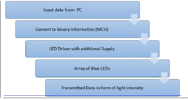
The designed system is partitioned into two independent units – a transmitter module and a receiver module. Inside the transmitting unit, the data is first converted to binary form using an ADC and then further fed into a LED driver circuit which is controlled by a signal processor.[10,11,12,13] The LED driver works on the principle of On-Off Keying modulation (Manchester encoding). After this the high illumination LED fluctuates at high frequency and transmits the data as optical pulses through the wireless medium. At the receiving unit, these optical pulses are sensed by a photodetector and interpreted into an electrical signal which is amplified by a transimpedance amplifier and then converted back to binary data using a comparator.
Fig. II : RECEIVER SECTION
II.
CIRCUIT
DESCRIPTION
In transmitter module, an array of blue LEDs was used to transmit light, which would be used to transmit data. The array pattern implementation has advantage of better range and higher performance as compared to a single LED. The source of the data that would be sent to the LEDs would be though the MCU of the transmitter circuit. The amount of power being sent to the LEDs from the MCU was low so the number of LEDs in the arrays were increased to improve the amount of power. For the switching purpose, a MOSFET IRFZ520 is used. The switch is in OFF state, when no voltage difference between gate and source and in ON state, when the gate is supplied with a voltage.
Fig. III : Circuit diagram of Li-Fi transmitter designed using Proteus Software
Fig. IV : Circuit diagram of Li-Fi Receiver designed using Proteus Software
III.
RESULTS
The data is transmitted and received in the form of light intensity or optical waves. At the transmitter module the binary data is processed from user readable form to electrical equivalent and then consequently in the form of pulses of light. Similarly at the receiver end the optical pulses are first converted into electrical equivalent quantity and then back to original format. The current and voltage were recorded at the receiver module keeping the transmitter fixed at a location and power was calculated using the product of voltage and current.
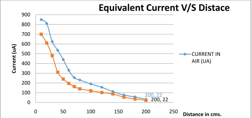
Fig. V (a), (b) : Plot of current in microamperes with respect to distance between transmitter and receiver in cms
The graph plotted in Figure 5 shows comparative currents measured at the receiver module with respect to distance from the transmitter module using line of sight observations. As the distance in increased the intensity of light sensed by photosensitive receptor decreases leading to lower values of generated electrical equivalent current.
200, 22
200, 22 0
100 200 300 400 500 600 700 800 900
0 50 100 150 200 250
Cu
rr
e
n
t
(u
A
)
Distance in cms.
Equivalent Current V/S Distace
Fig. VI (a), (b) : Plot of voltage in Volts with respect to distance between transmitter and receiver in cms
The graph plotted in Figure 6 shows comparative voltages measured at the receiver module with respect to distance from the transmitter module using line of sight observations. As the distance in increased the intensity of light sensed by photosensitive receptor decreases leading to lower voltage generation.
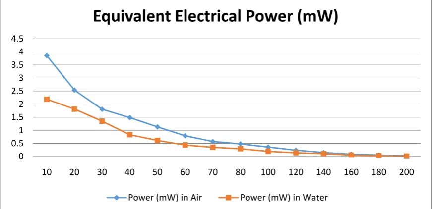
Fig VII (a), (b) : Plot of Power in milliWatts with respect to distance between transmitter and receiver in cms
The graph plotted in Figure 7 shows comparative powers measured at the receiver module with respect to distance from the transmitter module using line of sight observations. The power is the main parameter used for comparision of wireless data transmission. As the distance in increased the intensity of light sensed by photosensitive receptor decreases leading to lower voltage generation.
IV.
CONCLUSION
The graphs obtained were based on observation in normal conditions without any specified environment. The designed system allows the data transfer upto range of few meters after which the intensity of light gets reduced to such an extent that the solar panel is not able to retrieve the original data. The data is distorted due to noise factors. As observed from the graphs the electrical equivalent of binary data (both the current or voltage) sharply decreases as the range of transmission is increased. The range for successful data transfer depends on the intensity of light perceived by the receiving counterpart. Moreover the observations for aqueous media were recorded by keeping a suitable sized water body between the transmitter and receiver modules in order to allow the light waves to pass through the water. The rays were observed scattering as they
200, 0.68 200, 0.45
0 0.5 1 1.5 2 2.5 3 3.5 4
0 50 100 150 200 250
Vo
ltage
(Vo
lts)
Distance in cms.
Optical Voltage V/S Distance
VOLT IN AIR (V) VOLT IN WATER (V)
0 0.5 1 1.5 2 2.5 3 3.5 4 4.5
10 20 30 40 50 60 70 80 100 120 140 160 180 200
Equivalent Electrical Power (mW)
International organization of Scientific Research 10 | P a g e
pass through the aqueous medium. The electrical equivalent quantities were less in magnitude as compared to those recorded in non-aqueous media.FUTURE SCOPE
The designed system has manifold scope of betterment. To begin with the hardware components basically the LEDs can be replaced with high power LEDs to achieve better range. It is suggested to test with 1 Watt LED array which is expected to have about 10 times the range presently obtained although it would increase the power consumption requirements. The synchronization between receiver and transmitter parts prior to data transfer is another area of improvement. The designed system is on the Arduino with Serial Monitor test for synchronization which can be improved upon with better controllers and algorithms.
REFERENCES
[1]. H. Kaushal and G. Kaddoum, “Underwater optical wireless communication,” IEEE Access, vol. 4, no. 4, pp. 1518–1547,Apr. 2014.
[2]. William Charles Cox Jr. Simulation, Modeling, and Design of Underwater Optical Communication Systems. PhD thesis, North Carolina State University, 2012.
[3]. S. J. Tang, Y. H. Dong, and X. D. Zhang, “Impulse response modeling for underwater wireless optical communication links” IEEE Trans. Commun., vol. 62, no. 1, pp. 882–891, Jan. 2014.
[4]. F. Akhoundi, J. A. Salehi, and A. Tashakori, “Cellular underwater wireless optical CDMA network: Performance analysis and implementation concepts” IEEE Trans. Commun., vol. 63, no. 3, pp. 882–891, Mar. 2015.
[5]. Felix Stephan Schill. Distributed Communication in Swarms of Autonomous Underwater Vehicles. PhD thesis, The Australian National University, 2007.
[6]. Sathiya.T, Prof.E.Divya, Prof.S.Raja, “Visible Light Communication for Wireless Data Transmission”, International Journal Of Innovative Research In Electrical, Electronics, Instrumentation And Control Engineering Vol. 2, Issue 2, Feb. 2014
[7]. Mohamed Sufyan Islim and Harald Haas, “Modulation Techniques for LiFi”, (LiFi Research and Development Centre, Institute for Digital Communications, University of Edinburgh, April 13, 2016 [8]. Abhishek Kurup, Vipin Tiwari, Selvanathiya, “Implementation And Demonstration Of Li-Fi
Technology”, Ijret: International Journal of Research in Engineering and Technology eISSN: 2319-1163 | pISSN: 2321-7308
[9]. Ankita Choubey Deepak Sharma, “Comparative Study of Error Performance in Modulation Schemes for VLC Systems”, International Journal Of Engineering And Computer Science ISSN: 2319-7242 Volume 4 Issue 2 February 2015
[10]. N. Lourenc, D. Terra, N. Kumar, L. N. Alves, and R. L. Aguiar, “Visible light communication system for outdoor applications,” in Proc. 8th Int. Symp. Commun. Syst., Netw. Digit. Signal Process., 2012, pp. 1– 6.
[11]. Anurag Sarkar1, Prof. Shalabh Agarwal2, Dr. Asoke Nath3, “Li-Fi Technology: Data Transmission through Visible Light” International Journal of Advance Research in Computer Science and Management Studies, Volume 3, Issue 6, June 2015
[12]. Y. G Wang, X. X Huang, L. Tao, and N. Chi, “1.8-Gb/s WDM visible light communication over 50-meter outdoor free space transmission employing CAP modulation and receiver diversity technology,” in Proc. Opt. Fiber Commun. Conf. Exhib., 2015, pp. 1–4.
[13]. M. L Zhang, P. Zhao, and Y. J Jia, “A 5.7 Km visible light communications experiment demonstration,” in Proc. 7th Int. Conf. Ubiquitous Future Netw., 2015, pp. 1–3.