ISSN (e): 2250-3021, ISSN (p): 2278-8719
Vol. 08, Issue 01 (January. 2018), ||V1|| PP 01-05
Design and Construction ofa Single Phase Automatic Change
Over Switch
AyindeSaburAbiodun, OlawaleOlaniranKayode, BasseyEtidoNsukhoridem,
AmoduFunkeRoseline
Department of Science Laboratory Technology (Physics/Electronics), Federal Polytechnic, Ede, Osun State, Nigeria
Corresponding Author: AyindeSaburAbiodun
Abstract:
Considering the epileptic power supply in Nigeria and other developing countries today, a high demand of an alternative service is required. A single phase automatic change over switch from the public mains supply to the auxiliary supplies (single phase ac generator) and vice-versa has been developed. The design was realized using major components like a step down transformer (220V-12V dc), atmega8 microcontroller, rectifiers, voltage regulators, 555 timers, relays, circuit breaker and others like resistors, diodes, and capacitors. The device automatically switches from public mains to an auxiliary whenever there is an outage in the public mains. This device also detects the public main power supply when available and switches from auxiliary power supply to the mains with a delay period of 4 secondsin starting and switching off the generator. The device has been constructed successfully, and it demonstrated a tendency to automatically switch from mains to the auxiliarysource and vice-versa without human interception.Keywords: Automatic change over switch, Atmega8 microcontroller, contactors, relays, 555 timers
--- --- Date of Submission: 27-12-2017 Date of acceptance: 09-01-2018 --- ---
I.
INTRODUCTION
Power outage in general does not promote development to public and private sector. The investors do not feel secure to come into a country with constant or frequent power outage. These limit the development of industries. In addition there are processes that cannot be interrupted because of their importance, for instance surgery operation in hospitals, bank transactions and lots more. An automatic change over switch can be entertained to allow smooth and fairly uninterrupted supply of electricity for operation and services that require no discontinuity in electricity supply[1].This is achieved by the use of integrated circuits that have timing abilities and relays to effect switching [2].
Power supply instability in developing countries creates a need for automation of electrical power generation or alternative sources to back up the utility supply. This automation becomes predominantly high. Most industries and commercial processes are partly dependent on generators and public power supply. The public mains supply remains epileptic especially in tropical African countries where Nigeria forms a part. Therefore, if the processes of power changeover between these two power supplying sources are manual, human error during change over connections may occur; leading to machine damage, electric shock electrocution as well as increased down time consequently introducing massive losses.
Electricity plays a major role in economic development of a nation, and this forms the basis of this study, with interests in human, infrastructural and economic development. In most developing and undeveloped parts of the world, the supply of electricity for industrial, commercial and domestic use is highly unstable. This gives rise to the frequent use of alternative of power supply to meet up with the energy demands.
International organization of Scientific Research
2 | P a g e
Electrical changeover switch is another type of changeover switch, which involves the use of electrochemical type relays, contactors, voltage monitoring relays and delay timer relays as main components of the device [7]. The device is cheap and the construction is easy, but associated with noise in switching of relays, leading to wear and tear, loss of reliability, and thereby making the device to be prone to failures [6].
The electronic change over switch has proven to be a better device compared to both the manual and electrical changeover switch as it gives no noise, eliminates wear and tear, reduces damages to lives, and maintains high quality of service as it provide quick response for the interchanging of power to the load automatically from the main supply to the generatorand vice versa. The electronic changeover device employed in this research work changes over immediately when the public mains is out. However, the generator starter/off has a periodic delay to start/off the generator. This requires the generator to have a kick starter and off facility, and a battery in good condition [8].This paper presents the construction of a single phase power changeover switch that switches power supply from public mains supply to an auxiliary source (ac generator) and vice-versa.
II.
METHODOLOGY
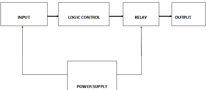
The circuit of the automatic change over switch can be described based on the construction block diagram shown in figure 1.
Figure 1: Block Diagram of Automatic Changeover Switch
The circuit consists of the varioussections stated: 1. Main supply section
2. Backup
3. Oscillator circuit 4. Switching circuit 5. Relay and load section.
The supply enters into the device from the main supply, and it also enters into the control circuit which consists of the rectifying circuit that supply dc signal to the time delay circuit. The timer delay receives the signal and delays it for some time according to a specific assigned value before allowing the signal to flow to the load. The relay is an electromechanical device which is capable of sensing variables like frequency, current and voltage. The relay receive the signal from the timer delay/switching circuit.
2.1 PRATICAL CONSIDERATION
The practical considerations to be taken into account when automatic changeover switch system is used are:
2.1.1 Voltage: - the voltage regulator unit automatically regulates the excitation of the generator, and hence the output voltage. In a DC to AC inverter, the voltage is regulated to meet the needed requirement.
2.1.2 Frequency: the frequency of the alternate source is regulated in a generator set, as frequency is determined by the speed of the driving engine. Closed loop speed control is used to regulate the generator’s frequency to supply the load at the standard frequency.
2.1.3 Synchronization: before transferring power through the Automatic changeover switch, the sources were put at the same voltage, phase sequence and phase shift.
2.2 DESIGN
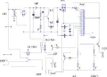
value IN4007 and the rectified signal is filtered by an electrolytic capacitor. The diode configuration is shown in figure 2.
Figure 2:Full wave rectifier
The switching transistor in the circuit switches the relay, and selects between the backup (generator) and the public supply. The relay is switched ON when the flip-flop is in SET mode. The relay or circuit breaker trips at 25% of dial spring settings. Current on the motor is known as rating current while that on circuit breaker is known as setting current. The current rating on dial spring is 25%, which implies that at any current setting on the breaker, there will be addition of 25% to the setting current before the circuit breaker of relay could be tripped OFF as a protective device for the equipment. The circuit breaker involve switches, motor, lamp, and it perform necessary switching when necessary/expected.
The atmega8 microcontroller used in the circuit is where the program for the logic control part of the device is coded by a suitable assembly language.
The circuit checks if mains supply is available, if not, it activates the kick starter of the generator and energizes the generator contactor. The load is supplied with generator.
As soon as the mains supply is available while running on generator, the circuit energizes the mains contactor and loads the circuit on mains. It then de-activates the generator starter. This de-energizes the generator contactor, and thereby turns off the generator in a delay time of 4 seconds. Conversely, the circuit waits till the mains fail, and then switches to the auxiliary. So is the system controls itself automatically.
International organization of Scientific Research
4 | P a g e
Figure 4:(a) Inner view of the constructed automatic changeover switch (ACS), (b)Cased ACS (Plastic caseis cheap, lessresistance to corrosion and can prevent some hazardscompared to a metalcase [9])
III.
TESTING AND EVALUATION
An open circuit test was carried out on the circuit to determine no-load loss and no-load current in the circuit connection. It was carried out using multimeter and mega dam tester. The connections from the output connector load to the input of mains (PHCN) contactor and generator contactor is ensured. The short circuit test carried out during energizing and de-energizing of the circuit indicates no variation in the output power.
Load and unload diagnosing were also carried out as troubleshooting, and it ensured perfect operation of the circuit.
The circuit was powered ON by the power switch. The circuit power supply was re-checked to ensure 5V is supplied to the Atmega8 microcontroller and 12V to the relays. All other connections (resistors, transistors, rectifiers, switches, capacitors) were ensured. An LCD display attached to the cover of the casing is a voltmeter for the mains and the generator as shown in figure 4.
A 60W incandescent light bulb was used as the load. ON/OFF switch is designed with the circuit that put the circuit in operation, and set to OFF mode if an alternative source is not required. Table 1 presents the summary of the operational evaluation of the circuit.
Table 1: Operational Evaluation of the Circuit Cases Mains
Contactor
Generator Contactor
Green LED (Mains Indicator)
Red LED (Generator Indicator)
Switch Observations
1. ON OFF ON OFF ON Mains is available and it supplies power to the load 2. OFF ON OFF ON ON Mains is out, and the
generator starts in 4s which supply power to the load 3. ON OFF ON OFF OFF Mains is available and it
supplies power to the load 4. OFF OFF OFF OFF OFF Mains is out. The alternative
source is out because the switch is reset to OFF mode. Hence, no power is supplied to the load
IV.
CONCLUSION
The device has been constructed successfully. This work was designed to contribute knowledge to technological development in the country, by creating a palliative measure to swift response to an alternative power supply due to our epileptic power supply.
International organization of Scientific Research
5 | P a g e
REFERENCES
[1]. Eshovo M. O.&Salawu A.(2017). Design, Construction and Testing of Voltage Sensitive Single-Phase Automatic Changeover Switch for Low Power Generators. FUW Trends in Science and Technology Journal, www.fistjournal.com, vol. 2, No.1A, pp 223-226.
[2]. Kolo, J. G. (2007). Design and Construction of an Automatic Power Changeover Switch. AU Journal of Technicial Report, 11(2), 1–6.
[3]. Gary Rochis&Glen Mazur(2001). Electrical Motor Controls. 9780826916754: Amazon.com: Books [4]. Ahmed, M. S., Mohammed, A. S., &Agusiobo, O. B. (2006). Development of a Single Phase Automatic
Change Over Switch. AU Journal of Technicial Report, 10(1), 68–74.
[5]. C, E. K., Uchenna, N., Henry, O. kelechi, &Amaka, E. (2015). Microcontroller Based Power Change-Over Switching System With Generator Shutdown. Journal of Multidisciplinary Engineering Science and Technology, 2(8), 2184–2189.
[6]. NwaforChukwubuikem M., MbonuEkene S., Uzedhe Godwin, (2012). “A Cost Effective Approach to implementing change over System”, Vol. 2, No. 2, March 2012, ISSN-L: 2223-9553, ISSN: 2223-9944, Pg. No’s 62-72
[7]. Agbetuyi, A. F., Adewale, A. A., Ogunluyi, J. O., &Ogunleye, D. S. (2011). Design and Construction of an Automatic Transfer Switch for a Single Phase Power Generator. International Journal of Scientific and Engineering Research, 2(May), 1–8.
[8]. Ezema, L. S., Peter, B. U., Harris, O. O., & Power, E. (2012). Design of Automatic Change Over Switch With Generator Control Mechanism. Natural Anf Applied Sciences, 3(3), 125–130.
[9]. Obikoya G. D., Zungeru A. M., Mmonyi A.C., &Hayatuddeen T. (2014). Design and Implementation of a Generator Power Sensor and Shutdown Timer. Innovative Systems Design and Engineeringwww.iiste.orgISSN 2222-1727 (Paper) ISSN 2222-2871 Vol.5, No.10
![Figure 4:(a) Inner view of the constructed automatic changeover switch (ACS), (b)Cased ACS (Plastic is cheap, lessresistance to corrosion and can prevent some hazardscompared to a metalcase [9])](https://thumb-us.123doks.com/thumbv2/123dok_us/7815509.1663815/4.595.73.523.467.665/constructed-automatic-changeover-plastic-lessresistance-corrosion-hazardscompared-metalcase.webp)
