ISSN (online): 2349-784X
Design and Performance Analysis of Pneumatic 3
Axes Robotic Arm for Mechanical Components
Urveshkumar Koshti Kuntal Deshpande
UG Student UG Student
Department of Mechanical Engineering Department of Mechanical Engineering Alpha College of Engineering and Technology, Ahmedabad,
India
Alpha College of Engineering and Technology, Ahmedabad, India
Ajay Singh
Assistant Professor
Department of Mechanical Engineering
Alpha College of Engineering and Technology, Ahmedabad, India
Abstract
An attempt has been made to add value to machine production automating repetitive tasks that could be done by automatic arms on the X-Y table. So we have arranged some kind of machinery regarding our aim will be fulfilled. At working conditions of the machine, workpiece handling is a difficult task for the worker especially in removing the workpiece from the die after machining. The paper proposes a cheap and effective method for the design and manufacturing of a three degree of freedom in a pneumatic way for the robotic arm. With this proposed approach the sequential design intents are captured, organized and implemented based on the entire system objectives, as opposed to the conventional design process which aims at individual components optimization. By considering the mechanical arm’s performance objectives, the design starts with modelling the integration of all the individual links constituting the manipulator. As a result, the proposed approach for manipulator design yields substantially less number of iterations, automatic propagation of design changes and the great saving of design efforts. Further with the best machining process and cheapest material, catering the strength and machining requirements suitable materials are selected to fulfill the objective. Keywords: Air compressor, Air, Air regulator, Arms, Cylinder clamps, Gripper, Pneumatic cylinders
________________________________________________________________________________________________________
I. INTRODUCTION
Industrial automation spans a broad field of applications from product automation to industrial plants. For all these applications, there are numerous challenges to be faced like reduced time-to-market, reduced costs, increased variability and expectations concerning higher quality.[1] As in the current scenario, there are many small and medium scale units that included the work like manual handling of the objects in the machines. As the current work, there are the workers working in hazardous conditions like the handling of the workpieces in the machines. They fit and remove the workpiece by manually as well as in the operating conditions of the machines. This type of work can be very dangerous for the workers. The environment can create hazardous with these types of conditions and there can create a problem for the whole unit. As in the injection molding machine, the workpiece has been created by pouring the hot material into the die and after the sometime workpiece has taken the desired shape according to die and that ready workpiece has been removed by manually by the worker sitting near to that of the machine. So there can decrease the productivity of the work and product. There can be more time-consuming activities due to this scenario that cannot be affordable by the whole unit especially in this fast and accurately machining scenario nowadays.
controlled by pneumatic principles so therefore reducing the complexity in designing, manufacturing, and machining and this helps in reducing the total cost of the robot right from designing to manufacturing since expensive electronic circuits are not used. When compared to electronic robots these pneumatic robots with simultaneous and sequential pneumatic circuits are capable of performing the same task automatically with the assistance of even unskilled labor which in turn reduces the running cost of the machine. These types of pneumatic robotic system can be used in places where repetitive action is required such as the assembly line and also in places where remote operation is required. The success and advancement of these types of the robot depends mainly upon the complexity of the pneumatic circuit. The effective design increases the efficiency and application of these robots.[5]
II. PROBLEM STATEMENT AND PROJECT OBJECTIVES
The problem generally faces the industries nowadays is that in the machine like Injection moulding the workpieces cut by the cutter and draw out them manually by workers. At working conditions of the machine, workpiece handling is a difficult task for the worker especially in removing the workpiece from the die after machining because of the high temperature of a workpiece. This creates hazardous tasks for every labour which can turn out as damage of a human body and parts permanently. This scenario mostly can see in a medium scale industry which cannot afford a highly automated machine against an intermediate profit margin. To fulfil our aim regarding our project. We have also taken of many kinds of literature which help us to decide our work plan and objectives to solve the issues.
1) The main objective of the work is to do automation in small and medium scale industries by the system with the low to medium running cost.
2) As the secondary objectives as like the reduce the time-consuming activities that were done by manually by workers and reduces as well as the hazardous effects created in the industries which can create serious issues by damaging their body parts. Robots may be used to perform tasks that are too dangerous or difficult for humans to implement directly or may be used to automate repetitive tasks that can be performed more cheaply by a robot than by the employment of a human or may be used to automate mindless repetitive tasks that should be performed with more precision by a robot than by a human (material handling, material transfer applications, machine loading and unloading, processing operations, assembly and inspection).
III. METHODOLOGY
Robots may be used to perform tasks that are too dangerous or difficult for humans to implement directly or may be used to automate repetitive tasks that can be performed more cheaply by a robot than by the employment of a human or may be used to automate mindless repetitive tasks that should be performed with more precision by a robot than by a human (material handling, material transfer applications, machine loading and unloading, processing operations, assembly and inspection).[6]Present wor k of the project sees the objectives on the eyes and tries those all the designs and other factors by which these objectives can fulfill and automation in the industry can be created. Present work included the pneumatic design with the supporting iron material frame and according to the pneumatically control design, air cylinder, air regulator and air gripper has fitted in that way that can perform the various tasks easily. To reduce the number of calculations, needed to determine the robot's exact position, the base is generally kept stationary.[7] As the scope of this project in the current scenario is that automation has created in industries, it reduces the hazardous activities and prevents the damages occurred by the activities of the old scenario. A low to medium cost robotic system can be implemented that is another advantage. This can increase productivity and reduce time-consuming activities.
The main objective of the proposed work is to design and fabricate the arm that is to pick the objects from the lower level and place it to the desired place at a higher level.
Project planning and methodology involves following steps:
Selection of Mechanism
By observing the working condition of material and objects handling like how they displace or remove the objects, we came to the conclusion by adopting a motion of the arm which gives a linear motion on the lifting of the air cylinder and gripper doing its action for grab the objects with another lifting up of the cylinder[8].
Design Consideration [5]
System specifications
1) Range 2) Load capacity
System configuration [5]
1) Number of Degree of freedom
2) Drive configuration (Electrical or Pneumatic) 3) Joints configuration
Design of supporting frame [5]
(IJSTE/ Volume 5 / Issue 10 / 005)
3D modelling
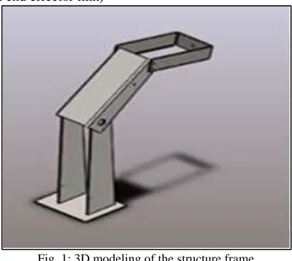
3D modeling of the software is done in the Solidworks software. Structure frame (including the base and end effector link)
Fig. 1: 3D modeling of the structure frame
Fig shows the support structure that has the base at the bottom and three links are to be joint by some joints. The end effector arm has connects the cylinder of the end effector. This cylinder connects the gripper which is pneumatically driven. So there are two air cylinder that one has connects the end effector and gripper and the second is to connect the first and second arms. The air has to be supplied directly through the air compressor so therefore connectors are used for converting air supply from different diameter pipe to the one common diameter pipe. For mounting the cylinder that has clamps or flange coupling that connects easily the cylinder to both sides of the arm/link. The air regulator has to be provided to regulate the flow of the air. A solenoid valve is provided to operate the cylinder at a particular time. A solenoid valve is an electromechanical actuated valve to control the flow of liquids and gases.[9] The given robotic arm will operate and perform its tasks by operating the solenoid valve, air cylinder, and gripper at the particular time. At the end of the arm, a wrist joint connects end effectors which may be a tool and its fixture or a gripper or any other device to work. Here how a pick and place robot can be designed for a workstation where loading and packing of lead batteries are been presented[10].
Table - 1
Volumetric properties of structure frame Treated as Volumetric Properties
Solid body
Mass: 0.64529 kg Volume: 8.06607e-005 m^3
Density: 8000.06 kg/m^3 Weight: 6.32385 N
Material Selection
The selection of appropriate material is necessary to build an efficient system where both performance and cost were accountable.[8] The most suitable material to fabricate the structure of the arm has to be light and strong.[11] The materials were selected such that it would withstand vibrations and the varying load acting on it.
The arterials used to build the system is AISI1020.
Design of Components
Selection of End Effector Cylinder
Pressure (P) supplied by the cylinder = 4 bar Let area of cylinder be A.
A=F/P
= 112.5/(4*105) =2.812*10-4 m2 A=3.14*d2 d=18.9 mm
We have taken 18.9 mm diameter to approximately 20 mm diameter. And the stroke length according to our need and structure design we taken a stroke length 80 mm. So cylinder used for the effector cylinder has a dimension of 20*80 mm.
Design of Body Cylinder Dimensions
Pressure= 4*105 N/m2 Area = force/pressure A= 6*9.81/(4*104) A= 14.715*10-4 A=3.14*d2
Therefore d= 21.647mm
Therefore we can take a body cylinder diameter value approximately as a 20 mm and stroke length as according to the structure frame and according to application stroke length taken as a 40 mm. So the dimension we take for the body cylinder is of the dimension 20*40 mm.
IV. RESULTS AND DISCUSSIONS
After designing and calculate the required data, we have to check whether this product is safe or not in a particular condition. So that with adding the iron (AISI1020) material, we checked for further analysis like stress, strain, and displacement. Stress can play a measured role in the analysis whether it is more in a loading area then product can go to fail and design cannot be safe. Same as displacement and strain, it also can be necessary that the product goes deform by which percentage at the particular condition. More deformation leads to failure in the design.
Analysis:
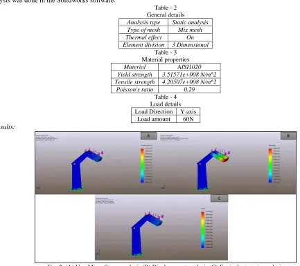
Analysis was done in the Solidworks software.
Table - 2 General details
Analysis type Static analysis Type of mesh Mix mesh Thermal effect On Element division 3 Dimensional
Table - 3 Material properties
Material AISI1020
Yield strength 3.51571e+008 N/m^2 Tensile strength 4.20507e+008 N/m^2
Poisson's ratio 0.29 Table - 4 Load details Load Direction Y axis
Load amount 60N
Results:
Fig. 2: (A) Von Mises Stress analysis (B) Displacement analysis (C) Equivalent strain analysis
a) Von Mises Stress:
(IJSTE/ Volume 5 / Issue 10 / 005)
data and the result data, the results data values are under the material properties value. So the design is then safe and this test shows that our project will not fail under stress.
Table - 5 Von Mises stress details
Type of Stress Min Max
Von Mises 0 N/m^2 Node: 6397
7.29171e+014 N/m^2 Node: 3998 b) Displacement Analysis:
Displacement analysis can be explained as the effect of stress acting on the object resulting in displacement. The result shows how many millimeters it displaces from its initial condition after giving the load. It shows the maximum 6.6 mm displacement which can negligible according to the conditions. The maximum displacement of the body occurs at the red color portion and the minimum displacement of the body occurs at the blue color portion as shown in fig 2 and the values of maximum and minimum displacement are as given in table 6. The values are under the limits of our product material. From the above fig, maximum displacement occurs on the end effector which indicates the red portion. The result of displacement is then safe. The value given in the table shows the effects of stress on our project.
Table - 6 Displacement details
Type Min Max
Displacement 0 mm Node: 6397
6.60374e+011 mm Node: 588 c) Equivalent Strain:
The strain is a measure of geometric response and the change in shape due to applied forces. [31] From the fig 2 the strain generally does not occurs at the high value so it has not a red color portion. The maximum stress occurs at the end effector as shown in the figure and the minimum strain has occurred at the first arm and has a dark blue color portion. The maximum and minimum strain values are in table 7. The result values are in the safe range of product material so it cannot fail during the load and change in shape. It is safe in a particular condition. The resultant values of the strain at a particular loading condition is as follows.
Table - 7 Equivalent strain details
Type Min Max
Equivalent strain 0 Element: 3085
1797.32 Element: 371
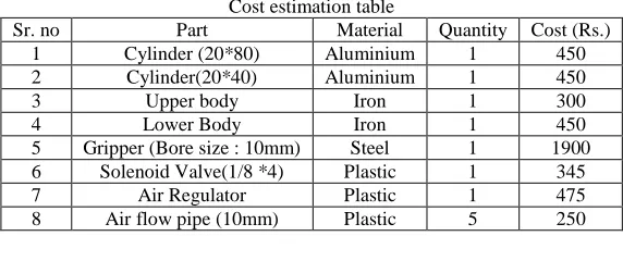
Cost Estimation
So according to the cost estimation, the project thus can be made for the maximum cost of the 7000 Rs. For lifting up the object up to 5 kg, the project has been made. The cost can be reduced and increase according to the requirements and mass production of the product.
Table - 8 Cost estimation table
Sr. no Part Material Quantity Cost (Rs.)
1 Cylinder (20*80) Aluminium 1 450
2 Cylinder(20*40) Aluminium 1 450
3 Upper body Iron 1 300
4 Lower Body Iron 1 450
5 Gripper (Bore size : 10mm) Steel 1 1900 6 Solenoid Valve(1/8 *4) Plastic 1 345
7 Air Regulator Plastic 1 475
8 Air flow pipe (10mm) Plastic 5 250
V. CONCLUSIONS
1) The manufacturing of the product with an effective and safe design has been performed as per the various tasks.
2) It can reduce human efforts, as well as the time-consuming activities, lead to an improvement in productivity of the various operations in the industries. Technical analysis has shown that it is economical viable.
3) It will be helpful for the industries and to improve the profits at low investment. 4) Improved robustness (consistency) of processes or products.
5) The objectives of the design and manufacturing the pneumatic mechanical industrial arm is been successful.
ACKNOWLEDGMENT
how to show your work in the report and research paper. We are also thankful for the overall project in-charge and the Head of Department, Alpha College of Engineering & Technology affiliated to Gujarat Technological University to grant permission for this project.
REFERENCES
[1] Jaikaran Singh, Mukesh Tiwari, Manish Shrivastava, “Industrial automation”, ISSN: 2231-5381, PP. 3516-3520, 2013
[2] Sanjay Lakshminarayan, Shweta Patil, “Position Control of Pick and Place Robotic Arm”, Department of Electrical Engineering MS Ramaiah Technology, Bangalore, India.
[3] Mamta B. Rajgor, Jayeshkumar Pitroda, “Automation: A New Millennium Technology for Construction Industries”, ISSN No 2277 – 8160, 2013, PP.79-81 [4] Hardik A. Modi, Dixit M. Patel , “Automated System Design For Pick & Place of M/C Components of CNC-Lathe” ISSN (online): 2349-6010, 2015, PP.
259-261
[5] Rakesh. N, Pradeep Kumar.A, Ajay.S, “Design And Manufacturing Of Low Cost Pneumatic Pick And Place Robot”, ISSN 2277-8616, 2013, PP. 131-133 [6] Mohamed Naufal Bin Omar, “Pick and Place Robotic Arm Controlled By Computer”, Faculty of Manufacturing Engineering, April 2007.
[7] Shweta Bisht, Anurag Jha, Bharat Rautela, “Experimental Performance Analysis of Pneumatically Driven Mechanical Robotic Arm for Pick and Place Operation” ISSN No. (Online) : 2249-3255, 2015, PP. 37-38
[8] Santosh C, Manoj C S, Akshay Peddarajula, Abhishek R Shetty, “Design and Fabrication of Pneumatic Arm for Pick and Place of Cylindrical Objects”, ISSN 2278-2540, 2016, PP. 111-113
[9] https://tameson.com/solenoid-valve-types.html
[10] S. Premkumar, K.Surya Varman, R.Balamurugan, “Design and Implementation of multi handling Pick and Place Robotic Arm”, ISSN: 2231-5381, 2016, PP. 164-166.
[11] Ravikumar Mourya, Amit Shelke, Sourabh Satpute, Sushant Kakade, Manoj Botre, “Design and Implementation of Pick and Place Robotic Arm” ISSN 2393-8471, April 2015 – September 2015, PP. 234-235.
[12] https://en.wikipedia.org/wiki/Von_Mises_yield_criterion