Modeling and Analysis for Obstacle Avoidance
of a Behavior-Based Robot with Objected
Oriented Methods
Qian Zhang
Department of Computer Science, University of Saskatchewan, Canada Email: [email protected]
Yong-Fei Zhang
School of Automation Science and Electrical Engineering, Beihang University, China Email: [email protected]
Shi-Yin Qin
School of Automation Science and Electrical Engineering, Beihang University, China Email: [email protected]
Abstract— Object Modeling Technique is widely applied in the field of software engineering; and in this paper we applied this technique to model a mobile robot including its behaviors and interactions with environment. The paper first describes key background knowledge about object oriented analysis in software engineering, behavior based robotics and their similarities. Then, based on these similarities, the paper uses object oriented methods of software engineering, such as unified modeling language (UML), to analyze and model the architecture; and to design behaviors for a behavior-based robot, which is expected to wander with autonomous obstacle avoidance in unknown environment. Object oriented methods permit a translation from concep-tual behavior models to computer programming representa-tions, and separate concrete control algorithms from robot modeling. With this approach, the paper implements a fuzzy algorithm for obstacle avoidance behavior of the constructed behavior models in a physical robot, and made experiments in the given indoor environment.
Index Terms— Behavior-based robotics, Objected oriented modeling, Obstacle avoidance, Mobile robot
I. INTRODUCTION
Object Modeling Technique (OMT) is the typical and probably most widely referenced modeling languages for software modeling and designing, especially for require-ment analysis [1]. Such method has been studied for many years in the field of software engineering since it was first developed around 1991. OMT is a predecessor of the Unified Modeling Language (UML), that is a standardized modeling language in software engineering today. With these standardized methods, now software engineering is highly industrialized.
In contrast to the standardized modeling technique for software engineering, modeling in robotics usually focuses on a specific part of a robot, but not on the whole system. For instance, many studies have been done for the model of controller for a particular behavior of a robot [2]–[4]. However, as a system, the behaviors of
This paper is supported by Laboratory of Pattern Recognition and Intelligent Systems, Beihang University, Beijing, China.
a robot can be treated as a whole and modeled in an aggregated level. Since object oriented method is a kind of systematical modeling method, it is highly possible to apply it to systems modeling in other research fields.
In our study, we treat the robot as a system and its behaviors as interactive parts of the system, and use ob-jected oriented methodology and UML to model a system of an autonomous robot, and also design its specific behaviors. The paper is organized as follow. Section 2 provides fundamental concepts of both object oriented method and behavior based robotics. In Section 3, we present our model of the robot system by using object modeling techniques. In Section 4, we describe the fuzzy algorithm for the obstacle avoidance behavior of the robot. Section 5 gives both simulated and practical experiments with the models and algorithm in previous sections, and Section 6 draws a conclusion.
II. BACKGROUND ANDRELATEDWORK
A. Introduction to Behavior-Based Robotics
The basic conception of behavior-based robotics (BBR) was firstly introduced by Brooks, R. [5]–[8], and this branch of robotics has been developed during the last twenty years by researchers around the world. The behavior-based approach aims at developing intelligent agent architectures, as well as effective control structures to control agents or physical robots. Because of high flexibility and reactive speed to unstructured environment, robustness and reliability of the system, and powerful capability of extending and learning, this approach has been applied widely in research of humanized robotics, bionics and even biology.
Besides, behaviors may probably interact with each other to communicate and exchange information. Therefore, it can be regarded that a behavior-based robot’s controller is a structured network consisting of interacting behaviors. [9]
Behavior-based robotics was founded on the Subsump-tion Architecture [5]. As a control strategy falling between planner-based robotics and reactive robotics, it establishes a mapping between conditions and actions [9], [10]. Besides, different from reactive robotics, it emphasizes internal states and their conversions for each behavior, and parallel, concurrently execution for all behaviors [11].
Another aspect which behavior-based robotics stressed is the architecture for the robot system but not algorithms. Unfortunately, some papers only focus on the design and algorithms for specific behaviors, but neglect the whole structure. Furthermore, the behavior-based approach also concerns about interactions between the robot system and outer environment. Real time changes from the environ-ment will certainly affect internal states of behaviors and the outputs of the system. This paper not only presents a detailed algorithm for obstacle avoidance behavior, but also an explicit structure for behaviors of the system and their interactions with environment
B. Ideas from Objected Oriented Software Engineering
The object oriented approach for system modeling generally includes four aspects: identity, classification, polymorphism and inheritance. [1] The object oriented analysis (OOA) aims at functional requirements and com-prehension of the application. It combines both a system’s behavior and data in different objects, organizes these objects as a structure, describes the way objects interact, and defines operations and attributes of objects.
’Object’ here is characterized by a certain number of operations and states which records the effects of these operations. [12] And an object oriented model consists of several different but possibly inter-related objects, which encapsulate individual behaviors, attributes and states. Another significant concept in object orientation is the use cases. Use cases are visual representations for varying software requirements, and provide a necessary and useful linkage between requirements, development, testing for the software system and its users. [12], [13]
Class in OOSE refers to a template for several ob-jects describing how these obob-jects structured internally. Bottom-up developing for objected orientation is to es-tablish a structure of classes with a set of attributes, behaviors, inheritance and associations among classes. And during the bottom-up induction, the system abstracts more reasonable super-classes and then subclasses could inherit more effective attributes and operations from their super-classes.
Object oriented development models concepts, but not implementations, i.e. it is a conceptual process indepen-dent of a specific algorithms until the final stage. Hence, object oriented methodology first emphasizes processes
of analysis and design (modeling) of an application do-main, and then detailed algorithm for implementation. This methodology is often called the Object Modeling Technique (OMT). [1]
C. Why Use Objected Oriented Approaches in Behavior-Based Robots Modeling
It must be pointed out firstly that ’behaviors’ for behavior-based robots are different from ’behaviors’ of an object or a class in object oriented software engineering, and actually the latter refers to the conception of ’op-eration’ in OMT. Hereby, the paper will use ’op’op-eration’ uniformly in next parts. From previous sections, it could be found that there are some similarities in conceptions and structures between behavior-based robotics and object modeling technique.
Initially,behavior-based robotics emphasizes control ar-chitectures, and object oriented software can be regarded as a system architecture for the object modeling tech-nique, which aims at providing a methodology to build a complete, flexible, robust and expanded software system. Secondly, although the object oriented modeling is a combination of both bottom-up and top-down developing method, the primary stage for this modeling approach fo-cus on building the software system bottom-up in order to collect fundamental classes to satisfy requirements from the users. Accordingly, the bottom-up developing method is still important in object oriented analysis and modeling. Behavior-based robotics is also structured and developed bottom-up, and hybrid systems which attempt a compro-mise between bottom-up and top-down by employing a planner based strategy in behavior-based robotics have been researched. [9]
Thirdly,behavior-based approach stresses internal states or representations of each behavior, and these states may trigger different actions of the following steps. Each object in object oriented software could hold various internal states in varied situations, though these states may not be crucial for the running of the whole system.
Finally, concurrent and parallel execution is another notable attribute of a behavior-based robot. Meanwhile it is an advantage for object oriented analysis and pro-gramming in contrast to conventional software developing methods. Multi-threading technique of programming and parallel algorithms provide availability for such parallel execution of several objects.
Based on above comparisons, we can say it is available or even effective to utilize the methodology of object oriented software engineering, to structure and model a behavior-based robot.
D. Related Work
[15], UML and object modeling techniques are applied in the Organization-based Multiagent Systems Engineering methodology to model the communications and interac-tions between agents and environment.
In this paper we takes advantages and methods of OOSE to model the structure of behavior-based robots and to implement behaviors with object oriented pro-gramming, in order to find to an effective approach for behavior-based robots modeling.
III. THE OBJECT ORIENTED MODELING FOR A BEHAVIOR-BASED MOBILE ROBOT In general, there are five major models in the process of object oriented software development: [12] (1) the requirement model, (2) the analysis model, (3) the design model, (4) the implementation model and (5) the test model. For our behavior-based robot system, the test model could be replaced with physical robot experiments. Hence, the paper pays little attention to the testing part, but more to the analysis and modeling for the structure and behaviors. Besides, the user interface (UI) design for most software is also neglected. And the implementation model is not presented for the limited paper length.
The behavior-based robot designed in this paper is expected to wander in unknown environment with au-tonomous obstacle avoidance. Three behaviors are defined as the Detecting Behavior, the Finding Path Behavior and the Obstacle Avoidance Behavior.
A. Use Case Model for Requirements Analysis
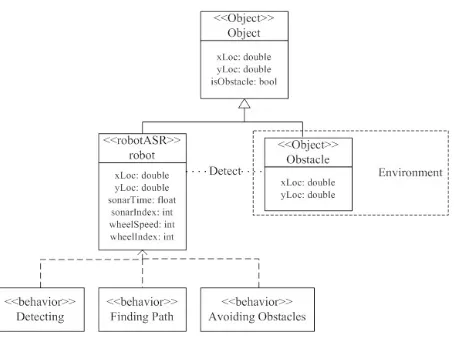
A requirement model for requirements analysis is mainly completed by use cases in the use case model, and the use case model also controls other parts of the system development. In the use case model, actors represent what will interact with the system and those need to communicate with the system. Use case model refers to what the system will perform after communication with both actors and other use cases. In paper [15], an interaction model and its corresponding environment model are defined to present agent (robot)-environment interaction. However, this model divided capabilities of a robot from the definition of robot. In our model, we consider a single robot and incorporate its model of behaviors into the the model of robot. Fig.1 is the use cases model for this behavior-based robot. Three use cases of the system (modeled as objects in the bottom of the figure) represent three behaviors for the robot, and the environment (the actor) provides outer information for the robot. And there are certainly interactions between the environment and use cases, and among use cases.
B. The Design Model
The main task of design modeling is to describe a sequence of stimuli, i.e. what action will make different use cases perform, and when they will perform. Sequence diagram is used to describe this sequence of stimuli to show how these use cases communicate with each other
Figure 1. The use cases model for the system
Figure 2. The sequence diagram for the system
or with the actor (the outer environment in this paper). Fig.2 represents the sequence diagram for the system. And this figure shows the process of how the information from environment ’stimulates’ behaviors of the system to perform and to transit. In a period of time (0.2 seconds in our physical experiment), sonars work one time, and the ‘detecting’ behavior is activated and the ‘finding path’ behavior will also start to work when ‘detecting’ behavior is normal. If the ‘finding path’ behavior gives back responses to show there are obstacles, the system will stimulate ‘avoiding obstacle’ behavior; if there is no obstacle, the ‘finding path’ behavior is activated again.
C. Object and Class Design
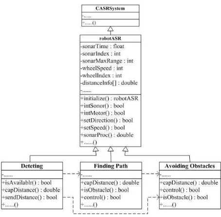
Based on the above use cases model and sequence dia-gram, the class designing aims at creating class diadia-gram, state transition diagram and activity diagram.
Figure 3. The class diagram for the system.
Figure 4. The state transition diagram for the detecting behavior
State and state transition for each behavior class are shown as the state transition diagram, and Fig. 4-6 shows internal states changes of these three behaviors. Fig. 4 is for the Detecting Behavior. Until the system receives stop command, sonars work periodically. Fig. 5 is for the Finding Path Behavior. Within this behavior it has two options of sub-behavior: going ahead and communicating with obstacle avoidance behavior, and the choice of these two sub-behaviors is based on the sonars information: whether ‘obstacle information’ is available. Fig.6 is for the Obstacle Avoidance Behavior. If the ‘obstacle infor-mation’ is true, which indicates there is an obstacle, the robot will call its obstacle avoidance controller; and if it is false, ‘obstacle avoidance’ behavior will feedback such information to the ‘finding path’ behavior.
Activity diagram shows the control stream of the whole system, and represents states and actions of each behavior, as well as their constraints.
Fig. 7 shows the activity diagram for the behavior-based robot system. State transition diagrams of behaviors and activity diagram for all behaviors work together to show the whole process of the robot system’s performance
Figure 5. The state transition diagram for the finding path behavior.
Figure 6. The state transition diagram for the obstacle avoidance behavior.
described above.
IV. FUZZY APPROACH FOR OBSTACLE AVOIDANCE BEHAVIOR
A. Fuzzy Controller
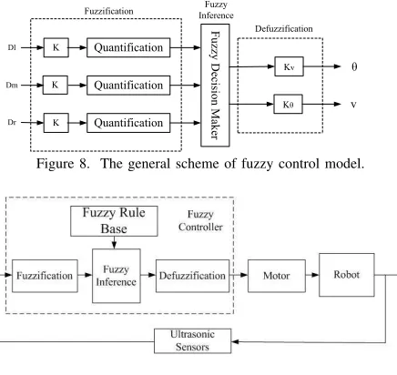
Since a wheeled mobile robot is a huge complex uncertain nonlinear system, the accurate dynamic and kinematics model is practically difficult to derive. Thus a fuzzy controller is proposed to implement the obstacle avoidance behavior, and is presented in detail in this section. The general scheme of fuzzy controller model for obstacle avoidance behavior of the mobile robot is shown in Fig. 8.
There are five ultrasonic sensors of the experi-mental robot for this paper. From the leftmost one to the rightmost one, these five sensors are defined as:S1,S2,S3,S4,S5, and the distances they get are denoted as D1,D2,D3,D4,D5
Quantification
Quantification
Quantification
Fuzzy Decision Maker
Kv K Dl Dm Dr K K K v Fuzzification Defuzzification Fuzzy Inference
Figure 8. The general scheme of fuzzy control model.
Figure 9. Fuzzy controller model.
Suppose the left front, the front and the right front distance of obstacles are the following:
Dl= min{D1,D2} (1)
Dm=D3 (2)
Dr= min{D4,D5} (3)
The obstacle avoidance behavior is to make the mobile robot avoid obstacles in a certain distance away from itself. The motion of the mobile robot will be changed by the control of its velocity(v) and steering angle(θ). Therefore, the input crisp variables of the fuzzy controller are the distance(Dm)of the robot (given by ultrasonic sensor) to obstacle positioned in its obverse front, as well as the information of distances of the robot to obstacle provided by the lateral ultrasonic sensors(DlandDr). The output crisp variables are chosen as the steering angle (θ) and the velocity (v) of the robot. Fig. 9 shows the model of this fuzzy controller [17].
B. Fuzzy Rules and Fuzzy Inference
It is much more complex for fuzzy inference with con-tinuous membership functions for large amounts of online inference and thus computations; hence these functions don’t meet the need for real time control of moving robots. In this paper, discrete membership functions pre-sented as fuzzy control tables with limited elements in the domain are adopted for the fuzzy controller.
The fuzzification of the input fuzzy variables consists in converting crisp input values to fuzzy membership degrees associated with each fuzzy predicate represented by linguistic variables. The input and output linguistic variables are expressed by the linguistic values and the linguistic terms have the following meanings:
TABLE I.
THE QUANTIFICATION TABLE OF FUZZY VARIABLEDi
Di -4 -3 -2 -1 0 1 2 3 4
VN 1.0 0.7 0.2 0 0 0 0 0 0
N 0.5 1.0 0.6 0 0 0 0 0 0
M 0 0 0 0.5 1.0 0 0 0 0
F 0 0 0 0 0 0 0.6 1.0 0.5
VF 0 0 0 0 0 0 0.2 0.5 1.0
TABLE II.
THE QUANTIFICATION TABLE OF FUZZY VARIABLEv
v -3 -2 -1 0 1 2 3
VS 1.0 0.6 0.2 0 0 0 0
S 0.5 1.0 0.5 0 0 0 0
M 0 0 0.5 1.0 0 0 0
Q 0 0 0 0 0.5 1.0 0.5
VQ 0 0 0 0 0.2 0.6 1.0
Di:
⎧ ⎪ ⎪ ⎪ ⎪ ⎨ ⎪ ⎪ ⎪ ⎪ ⎩
VN – very near N – near M – middle F – far VF – very far
i=l,m,r
And fuzzy output linguistic variables
v: ⎧ ⎪ ⎪ ⎪ ⎪ ⎨ ⎪ ⎪ ⎪ ⎪ ⎩
VS – very slow S – slow M – middle Q – quick VQ – very quick
θ: ⎧ ⎪ ⎪ ⎪ ⎪ ⎨ ⎪ ⎪ ⎪ ⎪ ⎩
LB – left big LS – left small M – middle RS – right big RB – right small
According to the varying range of distances from the robot to obstacles and effective detecting distances of ultrasonic sensors, the distance is divided into 9 classes averagely, defined as: -4, -3, -2, -1, 0, 1, 2, 3, 4. The proportional factor isk= 8/7since the effective distance of the sensor is [0m, 7m]; and the input variable of the controller can be quantified as y = k(x− 7/2), where x the input distance. Based on this classification and membership functions of the linguistic values, which come from our rich control experiences to the mobile robot, a quantification table of fuzzified variables (Dl,Dm andDr) according to the discrete membership functions, is shown in Table 1.
Similarly, quantification tables of fuzzified velocity and steering angle variables (θ and v)are also achieved by averagely dividing the varying range of velocity and steering angle into 7 classes respectively: -3, -2, -1, 0, 1, 2, 3. And the proportional factors arekv = 0.5,kθ= 15. Table 2 and 3 show these quantification processes based on their fuzzification membership functions.
TABLE III.
THE QUANTIFICATION TABLE OF FUZZY VARIABLEθ
v -3 -2 -1 0 1 2 3
LB 1.0 0.6 0.2 0 0 0 0
LS 0.5 1.0 0.5 0 0 0 0
M 0 0 0.5 1.0 0 0 0
RS 0 0 0 0 0.5 1.0 0.5
RB 0 0 0 0 0.2 0.6 1.0
linguistic values after fuzzification, there certainly will be
53 = 125 fuzzy rules to form the rule base, e.g. one of
them is as the following:
ifDl = N and Dm = N and Dr = F, then v =
S andθ=RB.
With these fuzzified input data, the fuzzy sets asso-ciated with each action of the behavior are determined by inferring from each activated fuzzy rule. The outputs of fuzzy controllers, θand v are inferred by using the Mamdani’s compositional rule for inference. Therefore, from the above 125 rules of fuzzy controller, two sets of 125 fuzzy relation matrices can be obtained respectively:
Rv1,Rv2, ...,Rv125 and Rθ1,Rθ2, ...,Rθ125. For instance,
for the above rule:
ifDl = N and Dm = N and Dr = F, then v =
S andθ=RB.
There are fuzzy relation matrices as the following:
Rv1=ND
l×NDm×FDr −→Sv (4)
R
θ1=NDl×NDm×FDr −→RBθ (5)
The total fuzzy relation matrices inferred by the Mam-dani’s compositional rule is as the following:
R˜v=
125
i=1
R˜vi (6)
Rθ˜=
125
i=1
Rθ˜
i (7)
For fuzzy input variables (Dl,DmandDr),the outputs of the fuzzy controllerθandvare:vare:
v= (Dl ×Dm ×Dr )◦R˜v (8)
θ= (Dl ×Dm ×Dr )◦Rθ˜ (9)
The defuzzification method to compute the crisp control actions vandθwas the center of gravity method [2].
v=
7
j=1vjµ(vj) 7
j=1µ(vj)
(10)
θ=
7
j=1θjµ(θj) 7
j=1µ(θj)
(11)
Initial Position (0, 350) Initial Angle: -50
Initial Position (0, 250) Initial Angle: 0
(a) (b)
Initial Position (0,0) Initial Angle 40
Initial Position (0, 0) Initial Angle: 60
(c) (d)
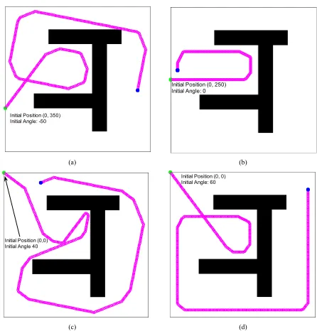
Figure 10. Simulations of the fuzzy controller for obstacle avoidance.
By the defuzzification, the crisp outputs can be con-verted from membership functions of fuzzy outputs. The final crisp outputs of the controller are then obtained as the product of the crisp outputs and their respective proportional factors kθ= 15,kv= 0.5.
With different combinations of conditions, controlled variables can be calculated and a 3-dimensional look-up table could be obtained; however, it is too space-consuming to display here. For practical controls, after the fuzzification from system’s inputs to relevant degree of quantification, controlled variables can be examined from the look-up table and then sent to the actuator.
C. Simulations
Because all the inference and computation are com-pleted off-line and a 3-dimensional look-up table is avail-able before the practical control of the mobile robot, only on-line table looking-up is needed during the control pro-cess. Thus, this approach needs few online computations, and it could satisfy requirements of real time control. Fig. 10 includes four simulations of the above fuzzy controller. In the designed environment with obstacles, the simulated robot starts to wander from different initial positions and with different forwarding angles, and stops when the obstacle is beyond the range of its detection. The simulating results prove the validity of the above fuzzy controller.
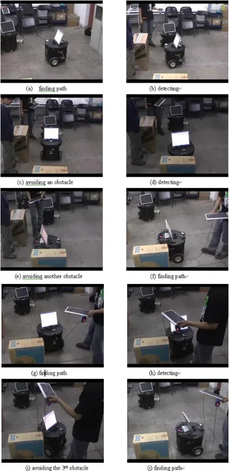
Figure 11. A process of obstacle avoidance.
V. EXPERIMENTS
Object oriented programming approach is used to re-alize the model described above. A series of experiments was conducted by using the proposed strategy in the platform of the AS-R mobile robot with C++ in the indoor environment with the dimension approximately7m×7m, and with obstacles as the above simulations indicate. Three defined behaviors are executed alternately, and the robot is able to wander without collisions, independently of the environment structure. Photos in Fig. 11 show the process.
VI. CONCLUSION
In this paper, the main objective to introduce of object oriented methodology in behavior-based robot modeling
is to facilitate the modeling and analysis of complicated robot’s behaviors and a multi-robot system’s behavior. The methods of object oriented modeling and analysis provide a natural translation from conceptual behavior models to computer representations. With object oriented modeling methods, the concrete algorithms are separated from the modeling of robot. That is, with a set of models for a robot or a multi-robot system, the user could concentrates on the control algorithms (here we used a fuzzy controller). The physical experimental results show such method is effective to a certain extent and deserves further concerns in the field of robot modeling. Finally, for the future work, we are aiming at extending this approach to the formation control of a multi-robot system, which is much more complicated for both modeling and control algorithms.
ACKNOWLEDGMENT
The paper is a part of the project of multi-robots for-mation control in Laboratory of Pattern Recognition and Intelligent Systems, Beihang University. We are indebted to anonymous reviewers for their helpful comments and suggestions. We should also give our appreciation to our colleagues in the lab and special thanks to Miss Xin Wang and Mr. Hua Wu in Beihang University for their kind help and supports.
REFERENCES
[1] J. Rumbaugh, M. Blaha, W. Premerlani, and W. L. F. Eddy,
Object-Oriented Modeling and Design. Prentice-Hall, 1991.
[2] C. C. Lee, “Fuzzy logic in control systems: Fuzzy logic controller, part i and ii,” IEEE Trans. Systems, Man and Cybernetics, vol. 20, no. 2, pp. 404–435, 1990.
[3] X. Zhang, “Fuzzy control system for a mobile robot colli-sion avoidance,” inIndustrial Technology, 1994, Proceed-ings of the IEEE International Conference on, December 1994, pp. 125–128.
[4] I. N. da Silva, F. A. C. Gomide, and W. C. do Ama-ral, “Navigation of mobile robots using fuzzy logic con-trollers,” inAdvanced Motion Control. The 5th Interna-tional Workshop on AMC ’98-Coimbra., 1998, pp. 346– 349.
[5] R. Brooks, “A robust layered control system for a mobile robot,” IEEE Journal of Robotics and Automation, vol. RA-2, pp. 14–23, April 1986.
[6] J. C. R. Brooks, “Synchronous distributed control system for a mobile robot,” inThe Proceedings of SPIE Intelligent Control and Adaptive Systems, Cambridge, MA, 1986, pp. 77–84.
[7] R. Brooks, “Intelligence without reason,” inThe proceed-ings of IJCAI-91, August 1991, pp. 569–595.
[8] ——, “Integrated systems based on behaviors,” in The proceedings of SIGART on Integrated Intelligent Systems, July 1991.
[9] http://robotics.usc.edu/ maja.
[11] M. Kasper, G. Fricke, and E. V. Puttkamer, “A behavior-based architecture for teaching more than reactive behav-iors to mobile robots,” in Third European Workshop on Advanced Mobile Robots, EUROROB 99, Zurich, Switzer-land, September 1999.
[12] I. Jacobson, M. Christerson, P. Jonsson, and G. Over-gaard, Objected-Oriented Software Engineering, A Use
Case Driven Approach. ACM Press, 1992.
[13] I. Jacobson, “Objected-oriented in an industrial environ-ment,” inThe Proceedings of OOPSLA’87, vol. 22, no. 12. SIGPLAN Notices, 1987, pp. 183–191.
[14] G. R. no and J. G´oez, “jmarkov: An object-oriented framework for modeling and analyzing markov chains and qbds,” inThe Proceedings of the SMCtools’06, Pisa, Italy, October 2006.
[15] S. A. DeLoach and J. L. Valenzuela, “An agent-environment interaction model,” in AOSE 2006 LNCS 4405, L. Padgham and F. Zambonelli, Eds. Berlin Heidelberg: Springer-Verlag, 2007, pp. 1–18.
[16] S. G. R. C. Ltd, The User Guidance Manual of AS-R Intelligent Robot, Shanghai, China, 2004.
[17] Q. Zhang, Y.-F. Zhang, and S.-Y. Qin, “A fuzzy control based obstacles avoidance strategy with scilab for a mobile robot,” in SCILAB Research, Development and
Appli-cations, International Workshop on SCILAB and Open
Source Software Engineering. Tsinghua Univesity Press, October 2005.
Qian Zhang is currently a Master student in University of Saskatchewan, Canada. She received her BEng degree in Com-puter Science and Technology in Taiyuan Univeristy of Tech-nology, Shanxi, China in 2004. Her research interests includes multi-robot system, computer vision, multi-agent systems and health informatics.
Yongfei Zhangreceived his BEng degree in Automation from Beihang University, Beijing, China in 2005. He is currently a PhD student in Beihang University, and a visiting student in University of Missouri, Columbia. His research interests in-clude image/video processing, video communication and pattern recognition.