Volume 5, Issue 2 (December 2012), PP. 20-26
A Composite Robotic Controller Design Using Reduced
Order Observer, Output Feedback and LQR and Its
Application to Two Link Manipulator
Sanjay Bhadra
1, Parijat Bhowmick
2, Prof. Gourhari Das
3 1,2 Dept. of Electrical Engg.(PG Control) Jadavpur University Kolkata, India,3
Dept. of Electrical Engg. Jadavpur University India
Abstract:–In this paper, an efficient method to linearize dynamic models about a linear trajectory for two link robot manipulators is developed from “straightforward” Lagrangian formulation and implementation of LQR (Linear Quadratic Regulator).This method is very simple and systematic. It can be applied to compute the feed forward control law (i.e. generalized forces and torques) about the desired trajectory (i.e. defined robot task space) and to design the feedback controller that reduces or eliminates any deviations from the target object placed in a defined robot space task. The salient advantage of this method is that the robot along with its system complexities can track target very efficiently and can lift the specified object effectively at specific position and angle by minimizing the steady state error. Computationally it has been found that this method tracks the target in much lesser time. Moreover, this method is very cost effective and economic.
Keywords:–Two Link Manipulator, Degrees of Freedom, Forward Kinematics, Lagrangian operator, Denavit-Hartenberg Transformation, Robotic Controller, Luenberger Observer, Das & Ghosal Observer, LQR (Linear Quadratic Regulator), PI Controller tuning
I.
INTRODUCTION
Robot manipulators exhibit structural flexibility. A nonlinear control law that incorporates manipulator dynamics as well as the application of an observer is developed in this paper. This technique is based on state feedback, output feedback along with a controller. The kinematics of the model represents the motion of the robot taking into considerations the forces which causes the motion. The robot manipulator operates in specified task space in which it moves along a specified direction and lifting the defined object at a specified angle. The model discussed here establishes a relation between force and torque taking into consideration the masses and moment of inertia. The different feedback used here shapes the local behavior of the system. The dynamics of the proposed model is a MIMO (Multiple Input Multiple Output) system. It is linearised and is expressed in state space model. The state of a dynamical system is basically a collection variables that permits the prediction of future development of the system. In this paper we explored the idea of controlling the system through feedback of the state. The feedback control is developed by positioning closed loop eigenvalues in desired locations. The state feedback actually stabilizes the system. We need the output feedback for tuning. If tuning is not done then we have to find the gain by trial. If only the output feedback is done response of the curve will be growing in nature and the plant will not be stabilized and as a consequence pole placement cannot be done. On the other hand if only state feedback is done desired performance may not be achieved. The results will come up with different errors such as steady state errors, overshoot, speed of response etc. Moreover, to make things desirable we use P/PI/PID controller so as to have the performance at requisite level. To use PID controller we have to use the connection from output to the input i.e. output feedback. Reduced order Das & Ghosal observer is implemented to measure the immeasurable states and to make the system sensor less. If sensor is used associated problems will be in costing and space allocation. Further use of observers eliminates the noise problems. Computer simulations are performed to verify the feasibility of robot manipulator along with the implemented observer. The experiments show that the proposed work produces good tracking performances in estimating the states yielding remarkably improved results.LQR is an elegant method for pole placement. Apart from LQR method for pole placement Ackermann‟s proposition is frequently used. But the drawback associated with this is that pole locations have to be chosen by trial and error method. But by LQR method pole placement policy is much easy to implement. Moreover it minimizes the control effort giving smart results.
II.
BRIEF THEORY ON ROBOTICS
A robot system consists of -
Manipulator
Sensory Devices
Controller
Power Conversion Unit
A. Manipulator:
actuator can be connected directly to the next Link or through some mechanical transmission. The Manipulator ends with a Link on which a tool can be mounted. The interface between the last Link and the tool or the end effectors is called Tool Mounting Plate or Tool Flange.
The Manipulator itself may be thought of as being composed of three divisions:
The major Linkages
The minor Linkages
The end Effectors
The manipulator is a collection of mechanical linkages connected by joints. The manipulator is capable of movement in various directions and is said to do “the work” of the robot. Generally the joints of the manipulator fall into two classes. The first, revolute joint produces pure rotary motion. Consequently the term rotary joint is often used to describe it. The second prismatic produces pure linear or translational motion and as a result it is often referred to as linear joint. Each joint of the robot defines a joint axis about or along which the particular link either rotates or slides (translates). Every joint axis defines a degree of freedom (DOF) so that the total number of DOF‟s is equal to the number of joints. The manipulator defined by joint-link structure generally contains three main structural elements: the arm, the wrist end the end effectors. Besides mechanical components most manipulators contain devices for producing the movement of various mechanical members. These devices are referred to as actuators and may be pneumatic, hydraulic or electrical in nature. They are invariably coupled to various to various mechanical links or joints (axes) of the arm either directly or indirectly.
B. Sensory Devices:
These devices monitor position, speed, acceleration and torque. The sensor is connected to actuator shaft. However it could be coupled to the output of transmission
C. Controller:
The controller provides intelligence to cause the Manipulator to perform in a manner described by its user. Each controller consists of:
A memory to store data defining the position
A sequencer to interpret the data stored in memory
A computational unit
An interface to obtain the sensory data into the sequencer
An interface to transfer sequencer information to the power conversion unit
An interface to ancillary equipment
D. Power conversion Unit:
This unit contains components required to take a signal from sequencer and convert it to the meaningful power level so that actuators can move.
III.
DYNAMIC MODEL OF TWO LINK MANIPULATOR:
First we shall calculate the potential energies of the system: K= 𝐾1+ 𝐾2
Where 𝐾1 = 1 2𝑚1𝑙1
2𝜃
12 (figure 3.1 has been taken as the model)
To calculate 𝐾2 , we first we will write the position equation for 𝑚2 and then differentiate it for the velocity of 𝑚2:
𝑥2 = 𝑙1𝑠𝑖𝑛𝜃1 + = 𝑙2sin(𝜃1+𝜃2) = 𝑙1𝑆1 + 𝑙2𝑆12
𝑦2 = - 𝑙1𝐶1 - 𝑙2𝐶12
X
Y
𝑙
1𝜃
1𝜃
2A
B
𝑚
1𝑚
2𝑦2 = 𝑙1𝑆1𝜃1 + 𝑙2𝑆12( 𝜃1 + 𝜃2 )
Since 𝑉2 = 𝑥2 + 𝑦2 we get
𝑉22 = 𝑙12𝜃12 + 𝑙22(𝜃12 + 𝜃22 + 2𝜃1 𝜃2 ) + 2𝑙1𝑙2(𝜃12 + 𝜃1 𝜃2 )( 𝐶1𝐶12 + 𝑆1𝑆12) = 𝑙12𝜃22 + 𝑙22(𝜃12 + 𝜃22 + 2𝜃1 𝜃2 ) + 2𝑙1𝑙2𝐶2(𝜃12 + 𝜃1 𝜃2 )
Then the kinetic energy for the second mass is
𝐾2 = 12𝑚2𝑙12𝜃12 + 1 2𝑚2𝑙2
2(𝜃
12 + 𝜃22 + 2𝜃1 𝜃2 ) + 𝑚2𝑙1𝑙2𝐶2(𝜃12 + 𝜃1 𝜃2 )
Fig 3.1: Two Link Manipulator And the total kinetic energy is K = 1
2(𝑚1 + 𝑚2) 𝑙1 2𝜃
2 + 1 2𝑚2 𝑙2
2(𝜃
12 + 𝜃22 + 2𝜃1 𝜃2 ) + 𝑚2𝑙1 𝑙2 𝐶2(𝜃12 + 𝜃1 𝜃2 )The Potential energy of the system can be written as:
𝑃1 = - 𝑚1g𝑙1𝐶1
𝑃2 = -𝑚2g𝑙1𝐶1 - 𝑚2g𝑙2𝐶12
𝑃 = 𝑃1+ 𝑃2 = - (𝑚1 + 𝑚2) g𝑙1𝐶1 - 𝑚2g𝑙2𝐶12
Using the Lagrangian technique, the first equation of motion is:
𝑇1 = [ ( 𝑚1 + 𝑚2)𝑙12 +𝑚2𝑙22 +2𝑚2𝑙1 𝑙2𝐶2]𝜃 1 + [𝑚2𝑙22 + 𝑚2𝑙1𝑙2𝐶2]𝜃 2 2𝑚2𝑙1𝑙2𝑆2𝜃 1𝜃 2 - 𝑚2𝑙1𝑙2𝑆2𝜃 22 + ( 𝑚1 + 𝑚2)𝑔 𝑙1𝑠1 + g𝑚2𝑙2𝑆12
Similarly,
𝑇2 = (𝑚2𝑙22 + 𝑚2𝑙1𝑙2𝐶2) 𝜃 1 + 𝑚2𝑙22𝜃 2 + 𝑚2𝑙1𝑙2𝑆2𝜃12 + g𝑚2𝑙2𝑆12
Writing these equations in matrix form
𝑇1
𝑇2 =
( 𝑚1 + 𝑚2)𝑙12 + 𝑚2𝑙22 + 2𝑚2𝑙1 𝑙2𝐶2 𝑚2 𝑙22 + 𝑚2𝑙1𝑙2𝐶2
(𝑚2𝑙22 + 𝑚2𝑙1𝑙2𝐶2) 𝑚2𝑙22
𝜃 1
𝜃 2 +
0 −𝑚2𝑙1𝑙2𝑆2
𝑚2𝑙1𝑙2𝑆2 0
𝜃12
𝜃 22
+ −𝑚2𝑙1𝑙2𝑆2 −𝑚2𝑙1𝑙2𝑆2
0 0
𝜃 1𝜃 2
𝜃 2𝜃 1 + 𝐴
𝐵 … … (3.1)
Where A = ( 𝑚1 + 𝑚2)𝑔 𝑙1𝑆1 + g𝑚2𝑙2𝑆12 B = g𝑚2𝑙2𝑆12
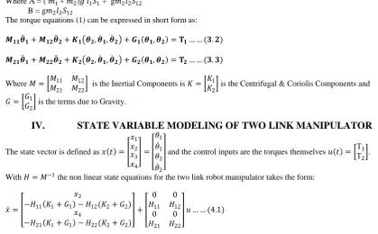
The torque equations (1) can be expressed in short form as:
𝑴𝟏𝟏𝜽 𝟏+ 𝑴𝟏𝟐𝜽 𝟐+ 𝑲𝟏 𝜽𝟐, 𝜽 𝟏, 𝜽 𝟐 + 𝑮𝟏 𝜽𝟏, 𝜽𝟐 = 𝚻𝟏… … (𝟑. 𝟐)
𝑴𝟐𝟏𝜽 𝟏+ 𝑴𝟐𝟐𝜽 𝟐+ 𝑲𝟐 𝜽𝟐, 𝜽 𝟏, 𝜽 𝟐 + 𝑮𝟐 𝜽𝟏, 𝜽𝟐 = 𝚻𝟐… … (𝟑. 𝟑)
Where 𝑀 = 𝑀11 𝑀12
𝑀21 𝑀22 is the Inertial Components is 𝐾 =
𝐾1
𝐾2 is the Centrifugal & Coriolis Components and
𝐺 = 𝐺1
𝐺2 is the terms due to Gravity.
IV.
STATE VARIABLE MODELING OF TWO LINK MANIPULATOR
The state vector is defined as 𝑥 𝑡 = 𝑥1 𝑥2 𝑥3 𝑥4 = 𝜃1
𝜃 1
𝜃2
𝜃 2
and the control inputs are the torques themselves 𝑢 𝑡 = ΤΤ1
2 .
With 𝐻 = 𝑀−1 the non linear state equations for the two link robot manipulator takes the form:
𝑥 =
𝑥2
−𝐻11 𝐾1+ 𝐺1 − 𝐻12(𝐾2+ 𝐺2)
𝑥4
−𝐻21 𝐾1+ 𝐺1 − 𝐻22(𝐾2+ 𝐺2)
+
0 0
𝐻11 𝐻12
0 𝐻21
0 𝐻22
𝑢 … … (4.1)
𝑥 𝑡 = 𝑥0+Δ𝑥 𝑡 =
𝜃10
0 𝜃20
0
+Δ𝑥 𝑡 𝑎𝑛𝑑 𝑢 𝑡 = 𝑢0+Δ𝑢 𝑡 = Τ10 Τ20 +
ΔΤ1(𝑡)
ΔΤ2(𝑡) … … (4.2).
From this the incremental linear state space model is obtained as: Δ𝑥 𝑡 = 𝐴Δ𝑥 𝑡 + 𝐵Δ𝑢 𝑡 … … (4.3)
Where
𝐴 =
0 1 0 0
− 𝜕
𝜕𝜃1
𝐻11𝐺1+ 𝐻12𝐺2 0 −
𝜕 𝜕𝜃2
𝐻11𝐺1+ 𝐻12𝐺2 0
0
− 𝜕
𝜕𝜃1
𝐻21𝐺1+ 𝐻22𝐺2
0 0
0
− 𝜕
𝜕𝜃2
𝐻21𝐺1+ 𝐻22𝐺2
1 0
𝑎𝑛𝑑 𝐵 =
0 0
𝐻110 𝐻120 0
𝐻210 𝐻220 0
… … (4.4)
Output equation will be 𝑦 = 1 0 0 0
0 0 1 0
𝑥1
𝑥2
𝑥3
𝑥4
The following numerical data have been taken for simulation purpose
𝑚1= 3𝑘𝑔; 𝑙1= 0.6𝑚; 𝐽1= 0.12𝑘𝑔𝑚2; 𝑚2= 2.5𝑘𝑔;
𝑙2= 0.8𝑚; 𝐽2= 0.15𝑘𝑔𝑚2;
𝑥1
𝑥2
𝑥3
𝑥4 =
0 1 0 0
17.832 0 −3.0024 0
0 0 0 1
−30.063 0 10.456 0
𝑥1 𝑥2 𝑥3 𝑥4 + 0 0 1.2514 −2.4337 0 0 −2.4337 6.5512 𝑢1
𝑢2 … … (4.5)
V.
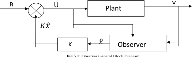
INTRODUCTION TO STATE OBSERVER
To implement state feedback control [control law is given by 𝑢 = 𝑟 − 𝑲𝒙 … … (5.1)] by pole placement, all the state variables are required to be feedback. However, in many practical situations, all the states are not accessible for direct measurement and control purposes; only inputs and outputs can be used to drive a device whose outputs will approximate the state vector. This device (or computer program) is called State Observer. Intuitively the observer should have the similar state equations as the original system (i.e. plant) and design criterion should be to minimize the difference between the system output 𝑦 = 𝐶𝒙 and the output 𝑦 = 𝐶𝒙 as constructed by the observed state vector 𝒙. This is equivalent to minimization of 𝒙 − 𝒙. Since 𝒙 is inaccessible, 𝑦 − 𝑦 is tried to be minimized. The difference 𝑦 − 𝑦 is multiplied by a gain matrix (denoted by M) of proper dimension and feedback to the input of the observer. There are two well-known observers namely – Luenberger Observer (1964, 1971) and Das & Ghosal Observer (1981). The second one has some genuine advantages over the first one. Das & Ghosal Observer construction procedure is essentially based on the Generalized Matrix Inverse Theory and Linear space mathematics.
Fig 5.1: Observer General Block Diagram
VI.
REDUCED ORDER DAS & GHOSAL OBSERVER APPLIED TO TWO LINK
MANIPULATOR
Reduced order Das and Ghosal observer is governed by the following equations and conditions.
𝑥 = 𝐶𝑔𝑦 + 𝐿 … … … (6.1) (eqn. 13 of [1])
𝑦 = 𝐶𝐴𝐿 + 𝐶𝐴𝐶𝑔 𝑦 + 𝐶𝐵 𝑢 … … (6.3) (eqn. 18 of [1])
= 𝐿𝑔𝐴𝐿 − 𝑀𝐶𝐴𝐿 + 𝐿𝑔𝐴𝐶𝑔− 𝑀𝐶𝐴𝐶𝑔 𝑦 + 𝐿𝑔− 𝑀𝐶𝐵 𝑢 + 𝑀𝑦 … … (6.4) (eqn. 19 of [1])
𝑞 = 𝐿𝑔𝐴𝐿 − 𝑀𝐶𝐴𝐿 𝑞 + 𝐿𝑔𝐴𝐶𝑔− 𝑀𝐶𝐴𝐶𝑔 + 𝐿𝑔𝐴𝐿 − 𝑀𝐶𝐴𝐿 𝑀 𝑦 + 𝐿𝑔− 𝑀𝐶𝐵 𝑢 … … (6.5) (eqn. 20 of [1])
𝑤𝑒𝑟𝑒 𝑞 = − 𝑀𝑦 … … (6.6) (Page-374 of [1])
𝐴𝑛𝑑 𝑥 = 𝐿𝑞 + (𝐶𝑔+ 𝐿𝑀)𝑦 … … 6.7 (eqn. 21 of [1])
VII.
COMPOSITE ROBOTIC CONTROLLER DESIGN USING REDUCED ORDER DAS
& GHOSAL OBSERVER & STATE FEEDBACK & MULTIPLE INTEGRATORS
Governing Equations:
1) 𝑥 = 𝐴𝑥 + 𝐵𝑢𝑖
2) 𝑌 = 𝐶𝑥
3) 𝑢𝑖= 𝐾𝑖𝑋𝑖− 𝐾𝑖𝑗𝑥 4) 𝑋 𝑖= 𝑟𝑖− 𝑌
5) 𝑞 = 𝐴 𝑞 + 𝐵 𝑢𝑖+ 𝐽 𝑌
6) 𝑥 = 𝐶 𝑞 + 𝐷 𝑌
𝑤𝑒𝑟𝑒 𝐴 = 𝐿𝑔𝐴𝐿 − 𝑀𝐶𝐴𝐿 ; 𝐵 = 𝐿𝑔− 𝑀𝐶𝐵 ;
𝐽 = 𝐿𝑔𝐴𝐶𝑔− 𝑀𝐶𝐴𝐶𝑔 + 𝐿𝑔𝐴𝐿 − 𝑀𝐶𝐴𝐿 𝑀 ;
𝐶 = 𝐿; 𝐷 = (𝐶𝑔+ 𝐿𝑀);
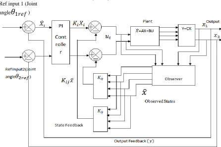
Main Features of the Composite Robotic Controller are:
State Feedback Controller
Optimal Pole Placement by LQR policy
Output Feedback
Reduced Order observer (Das & Ghosal Observer used)
Multiple Integrators (PI or PID controller can also be used)
Desired angular Positions specified as 𝜃1𝑟𝑒𝑓 & 𝜃2𝑟𝑒𝑓.
Ref input 1 (Joint
angle
𝜃
1𝑟𝑒𝑓
)
VIII.
DISCUSSION AND CONCLUSION
In this paper a two link robotic manipulator arm, having two joints (one shoulder joint and one elbow joint), has been used to move from one point to another point defined by its angular positions (𝜃1& 𝜃2). Reduced order Das & Ghosal observer has also been implemented in this application to estimate the two states – angular velocity of joint 1 and angular velocity of joint 2. Though these two states can be measured by external sensors but these are being estimated to replace the sensors thus saving space and reducing overall weight and cost of the setup. That‟s why observer has been used and other two states i.e. joint rotations can be easily measured by using rotary potentiometer or optical encoder or proximity sensors which are much simple to be set up. From the simulation responses (fig 8.1, 8.2, 8.3, 8.4) it is seen that the estimated states (indicated by red dotted line) got overlapped with the original states (indicated by blue continuous line) from the very beginning without any oscillations or steady state errors. In this simulation, the initial angular positions of the links are taken as 𝜃1= 45′& 𝜃2= −30′ respectively and their destination have been considered to be 𝜃1= −30′& 𝜃2= 45′. From the results, it can be inferred that the present robotic controller (a combination of state feedback controller, reduced order observer, output feedback and multiple integrators) is able to drive and control the two link manipulator system in a very efficient and effective manner. So this scheme can be applied to any other robotic system successfully.
To realize state feedback control all states are required to be fedback. So in practical robotic system also reduced order observer can be implemented successfully to estimate the states which are not accessible for direct measurement or very difficult to be measured. If all the eigen values of the observer dynamic system are properly chosen in the left half of „s‟ plane then it does not impair the stability of the overall system, it simply add it‟s own eigen values to the closed loop system‟s eigen values. Also the observer system does not degrade the performance of the original plant.
REFERENCE AND BIBLIOGRAPHY
[1]. G. Das and T.K. Ghosal, “Reduced-order observer construction by generalized matrix inverse”, International Journal of Control, vol. 33, no. 2, pp. 371-378, 1981.
[2]. Richard D. Klafter, Thomas A. Chmielewski, Michael Negin “Robotic engineering- An Integrated Approach” 2nd Edition, Prentice Hall India,1989
[3]. D. G. Luenberger, “Observing the states of a linear system” , IEEE Transactions Mil. Electron. vol. MIL-8,pp.74-80,April.1964
[4]. M. Gopal, “Modern Control system Theory” ,2nd Edition , New Delhi , Wiley Eastern Limited, April 1993 [5]. Elbert Hendricks, Ole Jannerup and Paul Hasse Sorensen, “Linear System Control- Deterministic and Stochastic
Method” ,1st
Edition, Berlin, Springer Publishers, 2008
[6]. Jian Xin Ju and Hidiki Hashimoto, “Robust Estimation and Control Of a single link manipulator with flexible joint” IEEE Transactions
[7]. M. B. Dias, M. B. Zinck, R. M. Zlot, and A. Stentz, “Robust multi robot coordination in dynamic environments”, Proceedings of IEEE International Conference on Robotics and Automation (ICRA '04), Vol. 4, 2008, pp. 3435-3442.
[8]. M. A. Batalin and G. S. Sukhatme, The analysis of an efficient algorithm for robot coverage and exploration based on sensor network deployment, in Proc. IEEE Int. Conf. Robot. Autom. (ICRA), 2007.
[9]. M.B. Dias, R.Zlot and N. Kalra, et al. Market-based multi robot coordination: a survey and analysis .Proc. IEEE,2007,94(7):1257-1270
[10]. J. A. T. Y. E. Kurabayashi, D. Ota, “Cooperative sweeping by multiple mobile robots,” in Proc. of IEEE International Conference on Robotics & Automation (ICRA), 2006