VOLUME 3, ISSUE 6, Jun.-2017
76 | P a g e
MAXIMUM POWER POINT TRACKING CONTROL FOR PHOTOVOLTAIC
SYSTEMS: NEURO-FUZZY APPROACH
MR. SWAPNIL L. DHAGE
M.E. Student, G. H. Raisoni Institute of Engineering and Technology, Pune Email ID: [email protected]
MRS. SANGITA B. PATIL
Assistant Professor, G. H. Raisoni Institute of Engineering and Technology, Pune Email ID: [email protected]
ABSTRACT:
The proper function of photovoltaic (PV) systems needs the design of an maximum power point tracking system (MPPT) to draw out the maximum possible power from the photovoltaic array. This paper investigates the efficiency of a neuro-fuzzy logic controller over conventional ones intended to track the maximum power point (MPP). The proposed model used for simulation studies is implemented using Matlab/Simulink. A comparison between the classical Perturb and Observe (P&O) algorithm and fuzzy algorithm in terms of MPPT accuracy is provided. Results prove that the proposed model is simple, reliable and allows simulation under different operating conditions.
KEYWORDS: photovoltaic; modeling; simulation; neuro-fuzzy logic; MPPT.
I. INTRODUCTION:
Solar output power of PV systems is generally influenced by atmospheric factors like variable temperature and solar irradiation. Different control techniques could be used on get rid of the miss functioning: controlling the input to the PV array and controlling the power output from the PV array. The combinations of these two may also be considered for maintaining constant output power at load [1]. The irradiance dependent input to the PV systems is controlled in order to be kept as high as possible, no matter the changes in weather conditions. Due to nonlinear I-V and P-V characteristics of the PV array, the MPPT becomes more challenging. Such linear and non-minimum phase characteristics further confuse the MPPT of the boost converter [5]. To overcome these problems, different conventional and intelligent MPPT algorithms have been proposed such as Incremental Conductance (IC) [6–8], Open Circuit Voltage (OCV) [9], Short Circuit Current (SCC) [10], Perturb and Observe (P&O) [11], fuzzy logic [12–15], feedback linearization [16], neural network [17– 22], neuro-fuzzy [23–25] and sliding mode [26,27]. Nevertheless, there still remains the concern of fast and accurately determining the locus of the MPP during high weather variations and external load changes occurring.
The fuzzy logic control is selected as it is effective and versatile, robust and flexible, without including control
algorithms methods that may not be appropriate for realistic implementations. It creates use of a thinking that is neither actual nor definitely inexact, but only to a certain level actual or inexact. The controller design is simple, mainly consisting of the conversion of a linguistic rules set into an automatic control algorithm. It does not require precise data, its reasoning schemes being based on uncertain or imprecise information. The output control is a smooth control function despite a variety of input variations. The fuzzy logic controller processes user defined rules that can be easily modified, to improve the system performance [2-5].
VOLUME 3, ISSUE 6, Jun.-2017
controller over performs in terms of efficiency, power quality and MPP error. The paper is structured as follows: Section 2 focuses on the PV system. Section 3 presents the proposed controller design. Section 4 describes the performance of the proposed solution using detailed simulations, followed by the conclusion in Section 5.
II. MPPTCONTROL:
A successful MPPT-PV system design must take into consideration a few requirements. Stability is the most fundamental design requirement of a dynamic control system. In PV power systems, the switching mode converters are nonlinear systems and the output characteristics of solar array are also nonlinear. Therefore, stability is a critical factor to evaluate a PV MPPT control systems dealing with non-linearity. Besides this, in MPPT control systems, a good dynamic response is desirable for the fast tracking requirement. A good MPPT control algorithm needs to respond quickly to rapidly changing atmospheric conditions like temperature and illumination and track the maximum power points quickly. It is also important to design a MPPT control system robust to any kind of disturbances. The disturbances can arise from various sources, one of the most common problems is that the PV modules manufactured by different technologies
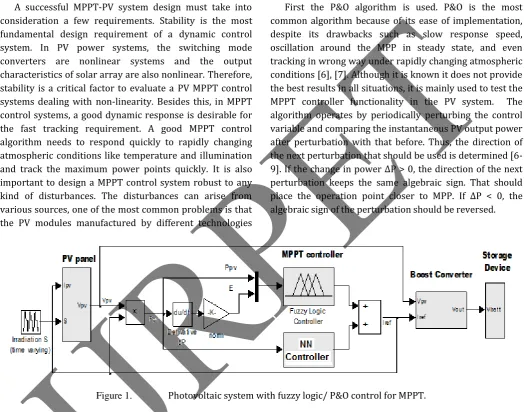
respond differently to the changes in solar insolation and cell temperature and this can cause the MPPT system to become inefficient. The basic layout of the photovoltaic system proposed includes a PV panel, a boost converter, a MPPT controller and a storage device (Fig. 1). The MPPT control is performed using two different methods.
A. P&O ALGORITHM:
First the P&O algorithm is used. P&O is the most common algorithm because of its ease of implementation, despite its drawbacks such as slow response speed, oscillation around the MPP in steady state, and even tracking in wrong way under rapidly changing atmospheric conditions [6], [7]. Although it is known it does not provide the best results in all situations, it is mainly used to test the MPPT controller functionality in the PV system. The algorithm operates by periodically perturbing the control variable and comparing the instantaneous PV output power after perturbation with that before. Thus, the direction of the next perturbation that should be used is determined [6-9]. If the change in power ΔP > 0, the direction of the next perturbation keeps the same algebraic sign. That should place the operation point closer to MPP. If ΔP < 0, the algebraic sign of the perturbation should be reversed.
Figure 1. Photovoltaic system with fuzzy logic/ P&O control for MPPT.
B. FUZZY LOGIC BASED ALGORITHM:
The second method of tracking the MPP is based on the fuzzy logic. The MPPT controller is generally composed of three main units: the fuzzification, the rule base and the defuzzification (Fig. 2) [10], [11].
Fuzzyfication
Inference
Defuzzyfication
Rule base
Inputs
Output
Figure 2. Block scheme of a fuzzy controller.
FUZZIFICATION:
VOLUME 3, ISSUE 6, Jun.-2017
78 | P a g e
variables are fuzzified by using trapezoidal MFs for P and triangular for E.
INFERENCE:
The second step is the inference, where the fuzzified variables are compared with predefined sets in order to get the appropriate response. It is responsible of the interpretation of the rules using information collected in the knowledge base to compute the fuzzy set output.
The fuzzy rules set are a collection of expert control knowledge allowing the fuzzy control objectives achievements. The control rules base is set up using IF-THEN rules, based on expert experience and engineering knowledge. Inference fuzzy rules for the PV system include 13 fuzzy control rules.
Mamdani fuzzy inference method is used with Max-Min operation fuzzy combination. This method implies the output membership function to be fuzzy sets. After the aggregation process, there is a fuzzy set for every output variable, leading to the necessity of a defuzzification. The operations used in the inference process are: And method is min; Or method is max; Implication is min; Aggregation is max.
DEFUZZIFICATION:
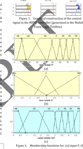
Defuzzification of the inference engine evaluates the rules based on a set of control actions for a given fuzzy inputs set. This operation converts the inferred fuzzy control action into a numerical value at the output by forming the “union” of the outputs resulting from each rule. In other words, the deffuzification plays the role of a linguistic-to-numerical data converter. The center of area (COA) algorithm is used for defuzzification of output control parameter Iref. The duty cycle of the boost converter is adjusted thought Iref such that the system operates at the maximum power point. The coding of the membership functions for the otput Iref is identical to that of the input P: Negative Big (NB), Negative Medium (NM), Negative Small (NS), Zero (Z), Positive Small (PS), Positive Medium (PM) and Positive Big (PB). In Table 1 it is summarized the different fuzzy rules used in the fuzzy controller to track the maximum power point.
Tabel 1 Fuzzy rules
P E
NB NM NS Z PS PM PB
NEG NB NB NM Z PS PM PB Z NB NM NS PS PS PM PB POZ NM NM Z PS PS PB PB
Every rule of the rule base of the fuzzy logic system establishes a fuzzy relation between the input fuzzy sets and the output fuzzy set Iref. There are 13 rules in the system rule base that make up the control strategy. The 13 rules are presented to the end-user in if-then format like the one below:
R1: If P is NB and E is NEG then Iref is NB; R2: If P is NB and E is Z then Iref is NB; R3: If P is NB and E is POZ then Iref is NM; etc.
Figure 4 shows the membership functions of input and output variables. On the ox axis the universe of discourse is represented, while on oy axis there is the membership grade taking values between 0 and 1.
Figure 3. Graphical construction of the control
signal in the MPPT controller (generated in the Matlab Fuzzy Logic Toolbox).
(a)
(b)
(c)
Figure 4. Membership functions for: (a) input P, (b)
input , c) output Iref.
VOLUME 3, ISSUE 6, Jun.-2017
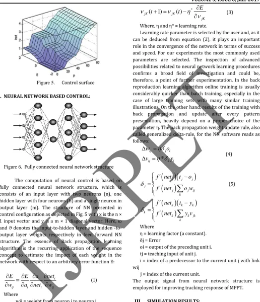
Figure 5. Control surface
C. NEURAL NETWORK BASED CONTROL:
Figure 6. Fully connected neural network structure
The computation of neural control is based on fully connected neural network structure, which is consists of an input layer with two neurons (n), one hidden layer with four neurons (h) and a single neuron in output layer (m). The structure of NN presented in control configuration as depicted in Fig. 5 with x is the n × 1 input vector and y is a m × 1 diagonal vector. Here, ω and ϑ denotes the inputhidden layer and hidden -to-output layer weights respectively in feed forward NN structure. The essence of Back propagation learning algorithm is the recurring application of the sequence concept to estimate the impact of each weight in the network with respect to an arbitrary error function E:
(1)
i i
ij i i ij
a
net
E
E
w
a
net
w
Where
wij = weight from neuron j to neuron i. ai = activation value.
Neti = weighted sum of the inputs of neuron i. Once the partial derivative of each weight is known, the aim of reducing the error function is achieved by performing a simple gradient descent:
(
1)
( )
ij ij
ij
E
w t
w t
w
(2)*
(
1)
( )
jK jK
jK
E
t
t
(3)Where, η and η* = learning rate.
Learning rate parameter is selected by the user and, as it can be deduced from equation (2), it plays an important role in the convergence of the network in terms of success and speed. For our experiments the most commonly used parameters are selected. The inspection of advanced possibilities related to neural network learning procedures confirms a broad field of investigation and could be, therefore, a point of further experimentation. In the back reproduction learning algorithm online training is usually considerably quicker than batch training, especially in the case of large training sets with many similar training illustrations. On the other hand, results of the training with back propagation and update after every pattern presentation, heavily depend on a proper choice of the parameter η. The back propagation weight update rule, also called generalized delta-rule, for the NN software reads as follows:
*
ij j i ij k i
w
o
v
y
(4)
j j j j
j j ij k
f
net
t
o
f
net
o w
(5)
k k k k
k k jk k
f
net
t
y
f
net
y v
Where
η = learning factor (a constant). δj = Error
oi = output of the preceding unit i. tj = teaching input of unit j.
i = index of a predecessor to the current unit j with link wij
j = index of the current unit.
The output signal from neural network structure is employed for improving tracking response of MPPT.
III. SIMULATION RESULTS:
VOLUME 3, ISSUE 6, Jun.-2017
80 | P a g e
The purpose of these simulations is to observe the time response and accuracy in terms of tracking the MPPT. For building the prototype 10W PV module is used considering the hardware development cost. The PV module has specification: solar panel power 10 W, open circuit voltage (Voc) 21.65 V, short circuit current (Isc) 0.69A, rated voltage 17.85 V, rated current 0.65 A. Figure 7 and 8 shows I-V Characteristics and P-V characteristics of 10W PV Module with constant radiation and varying solar radiation respectively. Figure 9 and 10 shows tracking of MPP at solar radiation 400 W/m2 and 700 W/m2 with change in external temperature. The tracking response is enhanced due to neural network structure with back propagation algorithm.
Figure 7. I-V Characteristics of 10W PV Module
Figure 8. P-V Characteristics of 10W PV
Module
Figure11. Tracking of MPP at 700 W/m2 & changing temperature condition
Figure 9. Tracking of MPP at 400 W/m2 &
changing temperature conditions
Figure 10. Tracking of MPP at 700 W/m2 &
changing temperature condition
Figure12. Tracking of MPP at 700 W/m2 & changing temperature condition
VOLUME 3, ISSUE 6, Jun.-2017
Figure 11, 12, 13 shows tracking responce of power based on neuro fuzzy, fuzzy logic & P and O methode respectively. The comparative analysis illustrate that, P and O methode gives Oscillatory response, which can be smooth with the help of fuzzy logic concept. But in case of fuzzy, desired power point tracking is not possible so that, Neural network combined in parallel with fuzzy logic controller.
IV.CONCLUSION:
In this work, an intelligent neuro-fuzzy direct method with high adaptive capability is designed for the MPPT of a PV system. A five-layer NFC is adopted as the process feedback controller. The proposed control is initialized from the traditional fuzzy control by means of expert knowledge, which decreases the weight of the lengthy pre-learning. With a produced learning plan, the factors are modified in the proposed structure adaptively by monitoring and modifying the tracking error. The simulator results show that the Neuro-fuzzy control algorithm considerably enhances the performance during the tracking phase as compared to a conventional algorithm of the maximum power point tracking (MPPT) in photovoltaic power systems. It provides fast response times and stability for changing environmental conditions. Stability and robustness is proven even in the case of a luminosity variation.
REFERENCES:
1) U. R. Yaragatti, A. N. Rajkiran, B. C.Shreesha, “A novel method of fuzzy controlled maximum power point tracking in photovoltaic system,” IEEE International Conference on Industrial Technology, 2005, pp 1421 – 1426.
2) M.S. Aït Cheikh, C. Larbes, G.F. Tchoketch Kebir and A. Zerguerras, “Maximum power point tracking using a fuzzy logic control scheme,” Revue des Energies Renouvelables, 2007, Vol. 10, N°3, pp 387 – 395. 3) G.Y. Ayvazyan1, G.H. Kirakosyan2, and A.H.
Vardanyan1, “Maximum Power Operation of PV System Using Fuzzy Logic Control,” Armenian Journal of Physics, vol. 1, 2008, pp. 155-159.
4) A. El Hajjaji, M. BenAmm
5) ar, J. Bosche, M. Chaabene, and A. Rabhi, “Integral Fuzzy Control for Photovoltaic Power Systems,”
Sustainability in Energy and Buildings, Springer Berlin Heidelberg, 2009, pp. 219-228.
6) N. Patcharaprakiti, S. Premrudeepreechacharn, Y. Sriuthaisiriwong, “Maximum power point tracking using adaptive fuzzy logic control for grid-connected photovoltaic system,” Renewable Energy, 2005, Vol 3, No 11, pp. 1771-1788.
7) Xuejun Liu and Luiz A. C. Lopes, “An Improved Perturbation and Observation Maximum Power Point
Tracking Algorithm for PV Arrays”, 35th Annul IEEE Power Electronics Specialists Conference, 2004, Vol. 3, pp. 2005-2010.
8) K. H. Hussein, I. Muta, T. Hoshino, and M. Osakada
“Maximum photovoltaic power tacking: An algorithm for rapidly changing atmospheric conditions”, Proc. IEEE - Generation. Transmission. Distribution, Vol. 142, 1\10. 1, Jan 1995, pp. 59-61.
9) W. Xiao, W.G. Dunford, “A Modified Adaptive Hill Climbing MPPT Method for Photovoltaic Power Systems,” 35th Annual IEEE Power Electronics Specialists Conference, 2004, pp. 1957-1963.
10)“Analysis of Perturb and Observe Maximum Power Point Tracking Algorithm for Photovoltaic Applications,” 2nd IEEE International Conference on Power and Energy (PECon 08), December 1-3, 2008, pp. 237-242.
11)A. Chouder, F. Guijoan and S. Silvestre, “Simulation of fuzzy-based MPP tracker and performance comparison with perturb & observe method,” Revue des Energies Renouvelables, Vol. 11, N°4, 2008, pp. 577 – 586. 12)W. C. So, C. K. Tse and Y. S. Lee, "Development of a
Fuzzy Logic Controller for DC-DC converters: Design, Computer Simulation, and Experimental Evaluation,”
IEEE Transactions on Power Electronics, Vol.11, No.1, January 1996, pp. 24-32.
13)Alajmi, B.N.; Ahmed, K.H.; Finney, S.J.; Williams, B.W.
Fuzzy-Logic-Control Approach of a Modified Hill-Climbing Method for Maximum Power Point in Microgrid Standalone Photovoltaic System. IEEE Trans. Power Electron. 2011, 26, 1022–1030.
14)Shiau, J.K.; Wei, Y.C.; Chen, B.C. A study on the fuzzy-logic-based solar power MPPT algorithms using different fuzzy input variables. Algorithms 2015, 8, 100–127.
15)Ramalu, T.; Mohd Radzi, M.; AtiqiMohd Zainuri, M.; Abdul Wahab, N.; Abdul Rahman, R. A photovoltaic-based SEPIC converter with dual-fuzzy maximum power point tracking for optimal buck and boost operations. Energies 2016, 9, 604.
16)Hadjaissa, A.; Ait cheikh, S.M.; Ameur, K.; Essounbouli, N. A GA-based optimization of a fuzzy-based MPPT controller for a photovoltaic pumping system, Case study for Laghouat, Algeria. In Proceedings of the 8th IFAC Conference on Manufacturing Modelling, Management and Control MIM 2016, Troyes, France, 28–30 June 2016; pp. 692–697.
VOLUME 3, ISSUE 6, Jun.-2017
82 | P a g e
18)Khaldi, N.; Mahmoudi, H.; Zazi, M.; Barradi, Y. The MPPT control of PV system by using neural networks based on Newton Raphson method. In Proceedings of the 2014 International Renewable and Sustainable Energy Conference (IRSEC), Ouarzazate, Morocco, 17– 19 October 2014; pp. 19–24.
19)Mohapatra, A.; Nayak, B.; Mohanty, K.B. Performance improvement in MPPT of SPV system using NN controller under fast changing environmental condition.
In Proceedings of the 2016 IEEE 6th International Conference on Power Systems (ICPS), New Delhi, India, 4–6 March 2016; pp. 1–5.
20)Ou, T.C.; Hong, C.M. Dynamic operation and control of microgrid hybrid power systems. Energy 2014, 66, 314– 323.
21)Hong, C.M.; Ou, T.C.; Lu, K.H. Development of intelligent MPPT (maximum power point tracking) control for a grid-connected hybrid power generation system. Energy 2013, 50, 270–279.
22)Ma, S.; Chen, M.;Wu, J.; Huo,W.; Huang, L. Augmented
Nonlinear Controller for Maximum Power-Point Tracking with Artificial Neural Network in Grid-Connected Photovoltaic Systems. Energies 2016, 9, 1005.
23)Messalti, S.; Harrag, A.; Loukriz, A. A new variable step size neural networks MPPT controller: Review, simulation and hardware implementation. Renew. Sustain. Energy Rev. 2017, 68, 221–233.
24)Subiyanto, S.; Mohamed, A.; Hannan, M.A. Intelligent maximum power point tracking for PV system using Hopfield neural network optimized fuzzy logic controller. Energy Build. 2012, 51, 29–38.
25)Khosrojerdi, F.; Taheri, S.; Cretu, A.M. An adaptive neuro-fuzzy inference system-based MPPT controller for photovoltaic arrays. In Proceedings of the 2016 IEEE Electrical Power and Energy Conference (EPEC), Ottawa, ON, Canada, 12–14 October 2016; pp. 1–6. 26)Abu-Rub, H.; Iqbal, A.; Ahmed, S.M. Adaptive
neuro-fuzzy inference system-based maximum power point tracking of solar PV modules for fast varying solar radiations. Int. J. Sustain. Energy 2012, 31, 383–398. 27)Rekioua, D.; Achour, A.Y.; Rekioua, T. Tracking power
photovoltaic system with sliding mode control strategy. Energy Procedia 2013, 36, 219–230.
28)Valencia, P.A.O.; Ramos-Paja, C.A. Sliding-mode controller for maximum power point tracking in grid-connected photovoltaic systems. Energies 2015, 8, 12363–12387.
29)Cheng, P.C.; Peng, B.R.; Liu, Y.H.; Cheng, Y.S.; Huang, J.W. Optimization of a fuzzy-logic-control-based MPPT algorithm using the particle swarm optimization technique. Energies 2015, 8, 5338–5360.
30)Liu, Y.H.; Liu, C.L.; Huang, J.W.; Chen, J.H. Neural-network-based maximum power point tracking methods for photovoltaic systems operating under fast changing environments. Sol. Energy 2013, 89, 42–53.
31)Vazquez, J.R.; Martin, A.D.; Herrera, R.S. Neuro-Fuzzy control of a grid-connected photovoltaic system with power quality improvement. In Proceedings of the 2013 IEEE EUROCON, Zagreb, Croatia, 1–4 July 2013; pp. 850–857.
32)Shanthi, T.; Vanmukhil, A.S. ANFIS Controller based MPPT Control of Photovoltaic Generation System. Res. J. Appl. Sci. 2013, 8, 375–382.
33)Lin, F.J.; Shen, P.H. Adaptive fuzzy-neural-network control for a DSP-based permanent magnet linear synchronous motor servo drive. IEEE Trans. Fuzzy Syst. 2006, 14, 481–495.
34)Atakulreka, A.; Sutivong, D. Avoiding local minima in feedforward neural networks by simultaneous learning.
In Australasian Joint Conference on Artificial Intelligence; Springer: Berlin, Germany, 2007; pp. 100– 109.
35)Choi, B.; Lee, J.H.; Kim, D.H. Solving local minima problem with large number of hidden nodes on two-layered feed-forward artificial neural networks. Neurocomputing 2008, 71, 3640–3643.
36)Lo, J.T.H.; Gui, Y.; Peng, Y. Overcoming the Local-Minimum Problem in Training Multilayer Perceptrons with the NRAE Training Method; International Symposium on Neural Networks; Springer: Berlin, Germany, 2012; pp. 440–447.
37)Lee, C.Y.; Lin, C.J. A wavelet-based neuro-fuzzy system and its applications. Intell. Autom. Soft Comput. 2007, 13, 385–403.
38)Abiyev, R.H.; Kaynak, O. Identification and Control of Dynamic Plants Using Fuzzy Wavelet Neural Networks.
In Proceedings of the 2008 IEEE International Symposium on Intelligent Control, San Antonio, TX, USA, 3–5 September 2008; pp. 1295–1301.
39)Cao, C.; Ma, L.; Xu, Y. Adaptive control theory and applications. J. Control Sci. Eng. 2012, 2012, 827353. 40)Rouzbehi, K.; Miranian, A.; Luna, A.; Rodriguez, P.
Identification and maximum power point tracking of photovoltaic generation by a local neuro-fuzzy model. In Proceedings of the IECON 2012—38th Annual Conference on IEEE Industrial Electronics Society, Montreal, QC, Canada, 25–28 October 2012; pp. 1019– 1024.