DOI 10.1007/s13173-011-0037-3 O R I G I N A L PA P E R
An algorithm to identify avoidance behavior in moving object
trajectories
Luis Otavio Alvares·Alisson Moscato Loy· Chiara Renso·Vania Bogorny
Received: 3 March 2011 / Accepted: 16 July 2011 / Published online: 30 August 2011 © The Brazilian Computer Society 2011
Abstract Research on trajectory behavior has increased significantly in the last few years. The focus has been on the search for patterns considering the movement of the moving object in space and time, essentially looking for similar ge-ometric properties and dense regions. This paper proposes an algorithm to detect a new kind of behavior pattern that identifies when a moving object is avoiding specific spatial regions, such as security cameras. This behavior pattern is called avoidance. The algorithm was evaluated with real tra-jectory data and achieved very good results.
Keywords Trajectory behavior·Spatiotemporal pattern· Moving objects·Trajectory data mining·Avoidance behavior
1 Introduction
Usage of location aware devices such as GPS and mobile phones has significantly increased in the last few years.
A previous version of this paper has appeared at GEOINFO 2010—The Brazilian Symposium on Geoinformatics. L.O. Alvares (
)·V. BogornyINE/UFSC, Florianopolis, Brazil e-mail:[email protected] V. Bogorny
e-mail:[email protected] L.O. Alvares·A.M. Loy II/UFRGS, Porto Alegre, Brazil A.M. Loy
e-mail:[email protected] C. Renso
KDD Lab, Pisa, Italy e-mail:[email protected]
These kinds of devices can generate sequences of space-time points capturing the trajectories of the object that carries the device. This kind of data—trajectory data—acquired for op-erational level use, is being generated at an incredible rate, and can be analyzed to obtain new knowledge; a higher level knowledge for decision making processes.
There are several real-world situations that consider spa-tiotemporal phenomena that are a target of analysis and re-search, as the pattern of humans buying items in a supermar-ket or a shopping center, animal migration behavior monitor-ing, human behavior in parks and cities, vehicle traffic, boat movement, etc. The study of trajectory behavior of these moving objects intends to transform these enormous quan-tity of raw data in useful information to the decision mak-ing process, knowledge discovery, and reality interpretation. It can contribute to problem solving (for instance, identify-ing fishidentify-ing areas [19]), to identify standards and tendencies, or to discover outliers, for instance. Trajectory data are ob-tained as a sequence of points(id, x, y, t ), where(x, y) rep-resent the geographic coordinates of the object id in the time instantt. We call this data as raw trajectories.
Many works have been developed over the last years con-sidering the study of trajectory behavior. These works have been developed according to two major research perspec-tives: a geometric one [3,6,8,9, 12] and a semantic one [2,4,5,17,18].
Some works analyze one trajectory at a time while oth-ers evaluate sets of trajectories using, for instance, clustering techniques. Several works search for some kind of similarity between trajectories: spatial format, time interval, velocity, stops at the same points, and so on. Those works discover different types of patterns, such as: flocks, convergence, leadership, encounter, co-location episodes, and so on.
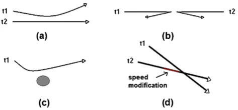
Fig. 1 Examples of the avoidance behavior
avoid some regions or that avoid other trajectories. For in-stance, people avoiding to collide with other people during a walk in a park, vehicles that change their route in situations of low speed traffic, or individuals that move in a suspicious manner avoiding vigilance cameras or security points.
An avoidance behavior can occur, for instance, when a trajectory avoids a specific spatial region, when one or more trajectories change their direction to avoid intersecting each other, or when one or more trajectories change their speed to avoid other moving objects, as can be seen in Fig.1. In Figs.1(a) and (b), the avoidance is between two trajectories and by direction changing. Figure1(d) presents an example of avoidance between two trajectories by speed changing, while (c) presents another kind of avoidance where a moving object avoids a static region.
This work presents a new algorithm able to identify an avoidance behavior where a moving object avoids a specific spatial region, as in the example shown in Fig.1(c).
The discovery of avoidance patterns in moving objects may be useful in several application domains, such as the discovery of individuals with suspicious behavior, avoiding monitoring cameras, police stations, blitz, and so on. Avoid-ance pattern discovery can be interesting for traffic applica-tions, with cars avoiding low traffic regions.
The remainder of this paper is organized as follows: Sect. 2shows the main related works, Sect.3presents the heuristics used to identify an avoidance, Sect. 4 presents the developed algorithm to recognize an avoidance pattern, Sect.5shows some experiments, Sect.6presents a discus-sion on the parameters of the algorithm, and Sect. 7 con-cludes the paper.
2 Related work
Detecting patterns of movement has been of interest since 1970, when Hagenstrand posed the bases of Time-Geography [10], where he first proposed the idea of “spa-tiotemporal prism” to represent the human movement. From that time, a number of approaches tried either to represent the human movement or to detect patterns from datasets of movement traces. The paper from Dodge et al. [7] presents
a taxonomy of movement patterns. The interesting part of this work is that they first proposed a systematic vision of the movement patterns distinguishing between generic and behavioral patterns, and the generic pattern is divided into compound and primitive. For example, a moving cluster is classified as a primitive pattern whereas a flock is a behav-ioral pattern. Despite the fact that this proposal is interesting as a tentative to classify the many movement patterns pro-posed in the last decade, we believe that some important patterns are not included as, for example, the avoidance pat-tern.
Several recent works define trajectory patterns basically considering the geometric part of trajectories. Laube in 2005 introduced the mobile group pattern, which is a set of trajec-tories close to each other, with distance less than a given threshold, for a minimal amount of time (minTime) [13]. In this approach, the direction is not considered and frequent groups are computed with the algorithm Apriori [1]. Laube also [12] proposed five types ofgeometrictrajectory patterns based on movement, direction, and location, convergence, encounter, flock, leadership, and recurrence. A flock pattern has at leastmsubtrajectories within a region of radiusrthat move in the same direction during a certain time interval. The leadership pattern must have at leastmsubtrajectories within a circular region of radiusr that move in the same direction, and at least one of the entities is heading in that direction for at least a certain time. Encounter is the pattern characterized by at leastmsubtrajectories that are concur-rently inside the same circular region of radiusr, assuming they move with the same speed and direction. Reccurrence patterns occur when at leastmentities visit a circular region at leastktimes.
In [6], collocation episodes in spatiotemporal data are computed, where groups of trajectories are spatially close in a time window and move together.
Another approach is the T-pattern [8]. It is a sequential trajectory pattern mining algorithm that first generates re-gions of interest considering dense rere-gions in space, and then computes sequences of regions visited, taking into ac-count transition time from one region to another and mini-mum support.
concept of collision-avoidance for planning the future tra-jectories of a robot.
On the contrary, our proposal aims at analyzing histori-cal GPS traces (trajectories) in order to detect the presence of avoidance patterns. This method is not intended for real time collision avoidance, but to detect a specific avoidance behavior in past trajectories. To the best of our knowledge, there are no similar approaches in the literature.
3 Heuristics to identify an avoidance behavior
The avoidance behavior pattern occurs when a mobile object is moving toward an object of interest or target object (as a surveillance or security camera, for example), shifts to avoid passing the object of interest, and after that goes back to its original path. The challenge is to differentiate what is really a shift to avoid the object of interest from a natural path change caused by another reason.
Some aspects that have to be considered are the follow-ing.
The moving object should not cross (intersect) the object of interest calledthe target object(the region covered by the security camera, for instance), because if the moving object changes its direction but yet crosses the target object, it did not stay away from the target and, therefore, does not char-acterize an avoidance.
The moving object should keep going in the direction to the target object (the object to be avoided) and deviate from the target object relatively close to it to be considered an avoidance. A counterexample is a person walking and one or more kilometers away he/she deviates from a security cam-era; this person is probably changing his/her direction by any other reason and not for escaping the security camera, therefore, not characterizing an avoidance behavior. To ma-terialize this idea, we created the concepts oftarget object
andregion of interest.Target objectis a convex spatial
lo-cation that a trajectory could avoid. Theregion of interestis defined by a distancedfrom the target object. Any behavior outside the region of interest is not considered because it is too far from the target object. Then a moving object must intercept the region of interest in order to characterize an avoidance.
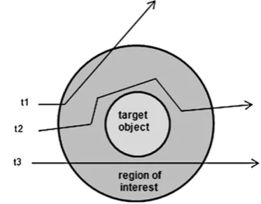
Figure2shows these intuitions. Trajectoryt1was mov-ing in the direction to the target object, deviated to avoid it, and after a while continued more or less on its original path, characterizing a case of avoidance. Trajectoryt2 moves in the direction to the target object and intersects it, without avoiding it and, therefore, not characterizing a case of avoid-ance. Finally, trajectoryt3was moving in the direction to the target object but changed its direction far away from the tar-get, and the deviation occurred outside the region of interest and, therefore, not characterizing an avoidance behavior.
Fig. 2 Example of target object, region of interest, and trajectories behavior
Fig. 3 Examples of trajectory behaviors
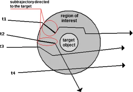
Even with the definition of region of interest, we ob-served that some trajectories, although intersecting the re-gion of interest and not crossing the target object, did not present a clear behavior of moving toward the target object before changing direction. In these cases, it is not possible to give to these trajectories a suspicious behavior, consider-ing the example of security cameras. Figure3shows some examples. The trajectoryt2clearly presents an avoidance be-havior, but for the trajectoriest1andt3this is not so obvious. In order to make more robust the identification of an avoidance behavior, we introduce the notion of subtrajectory directed to the target. Thesubtrajectory directed to the tar-getis the longest subtrajectory that is moving in the direction to the target object, inside the region of interest, with length greater or equal to a minimum lengthl. Then a new condi-tion to characterize an avoidance is: The trajectory should have asubtrajectory directed to the target. Figure4presents some examples of this concept. The trajectoriest1 andt2 have a subtrajectory directed to the target but the trajectories t3andt4do not.
relation to atarget objectoif it has asubtrajectory directed
to the targetoand does not intersect the target objecto.
However, if we observe the avoidance behavior of the tra-jectories in Fig.5, intuitively we can say that the avoidance of trajectoryt1is stronger than the avoidance of trajectoryt2, becauset1returns to its original path after deviating the tar-get object (the security camera), with a clear intent of avoid-ing the target. In the case of trajectoryt2, this is not so obvi-ous, because the trajectory deviated the camera and follows this new direction without returning to its original path.
To know if a trajectory returns to its original path or not after deviating the target, we create the notion ofa
confi-dence incremental region, denoted by a region inside the
re-gion of interest that does not contain the target object and is situated between the target object and the edge of the region of interest, on the opposite side of the subtrajectory directed to the target, with width equal the diameter of the target ob-ject. An example is shown in Fig.6. This region is unique for each trajectory considering a target object.
Intuitively, trajectory t1, in Fig. 6(a) presents an avoid-ance with greater degree of certainty than trajectory t2 in
Fig. 4 Example of subtrajectory directed to the target
Fig.6(b), becauset1 intersects the confidence incremental region. In this case, we are more sure that trajectoryt1has an intentional avoidance and we give an weight for this sit-uation. We create two levels of avoidance of one trajectory in relation to a target object:strong avoidance—when the trajectory intersects the confidence incremental region, and
weak avoidance—when a trajectory moves in direction to
a target, has a subtrajectory directed to the target, but nei-ther intersects the target nor the confidence incremental re-gion. This idea is mapped to a value, calledlocal avoidance
confidence(in relation to a specific target object): 0.0 for no
avoidance, 0.5 for weak avoidance, and 1.0 for strong avoid-ance.
A last heuristic is that if there is a region with several security cameras we can analyze the behavior of the whole trajectory in relation to the whole set of target objects. To do this, if a trajectory crosses the region of interest of sev-eral target objects, we can have a global avoidance value
for the whole trajectory, considering eachlocal avoidance
value. As a first approximation, we define the equation
Avti=
n k=1Avik
n (1)
whereAvtistands for the avoidance confidence for the whole
trajectoryi.Avikis the value of local avoidance for trajectory i in relation to the target objectk, and nis the number of regions of interest intersected by trajectoryi.
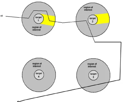
Figure7shows an example of avoidance confidence for a whole trajectory. Trajectory t1 has a strong avoidance considering the target object 1, a weak avoidance in rela-tion to the target object 2, and has no avoidance for tar-gets 3 and 4. Therefore, its global avoidance confidence is (1+0.5+0)/3=0.5. The target object 4 is not counted in the denominator because its region of interest is not inter-sected by the trajectory.
Fig. 6 Examples of confidence incremental regions
4 An algorithm for avoidance detection
Based on the heuristics presented in Sect.3, we propose an algorithm to detect avoidance patterns, in the pseudo-code shown in Listing1.
Initially, the algorithm tests the intersection of the trajec-tory points with the regions of interest of each target object (line12). Only the trajectory points that intersect any region of interest are considered in the rest of the algorithm, which significantly decreases the processing time. If the trajectory intersects the region of interest, then it is not an avoidance (lines14–15). The function SubtrajDT() (line17) returns the longest subtrajectory that goes to the target inside the region of interest. The pseudocode is presented in Listing 2 and is detailed later in this section. The function ConfIncrR() (line18of Listing1) determines the confidence incremental region, and is detailed later in Listing3. If the trajectory in-tersects the increasing confidence region in a time period af-ter the time period of the subtrajectory directed to the target, then the avoidance is strong (lines 19–20); otherwise, the avoidance is weak (lines21–22). The global confidence of the avoidance of a whole trajectoryiis computed in line29, using (1).
Listing 1 Pseudocode of the proposed avoidance algorithm
1 IN P U T: T / / s e t o f t r a j e c t o r i e s 2 O / / s e t o f t a r g e t o b j e c t s
3 d / / s i z e o f t h e b u f f e r f o r t h e r e g i o n o f 4 / / i n t e r e s t a r o u n d t h e t a r g e t o b j e c t 5 subt / / m i n i m a l s i z e o f t h e s u b t r a j e c t o r y 6 / / d i r e c t e d t o t h e t a r g e t
7
8 OUTPUT: Avt / / s e t o f d e g r e e s o f a v o i d a n c e 9
10
11 METHOD:
12 F O R each ti∈T | intersects(ti,buffer(O,d) ) DO 13 F O R each ok∈O DO
14 I F intersects(ti,ok)
15 avik=none
16 E L S E
17 I F SubtrajDT(ti,ok,d) >= subt
18 CIR=ConfIncrR(ti,ok,d)
19 I F intersects(ti,CIR)
20 avik=st rong
21 E L S E
22 avik=weak
23 E N D I F 24 E L S E
25 avik=none
26 E N D I F 27 E N D I F 28 ENDFOR 29 calculate Avti
30 ENDFOR 31 return Avt
The function SubtrajectoryDT() shown in Listing2, con-siders the first trajectory point inside the region of interest and takes the next points, one by one, while the direction of the line segment from the initial point to the last con-sidered point intersects the target object. This procedure is repeated for the next points to determine the longest sub-trajectory directed to the target inside the region of inter-est.
As shown in Listing2, the procedure starts with the two first trajectory points that intersect the region of interest of the target object being considered (lines11–12) and a loop is performed for all points in P (lines 14–29). Inside the loop, the first step is to calculate the azimuth between the two points to determine the direction of the trajectory and to extend this line segment until a possible intersection with the target object occurs (lines15–17). If the line segment in-tersects the target object, then the mobile object is moving in the direction to the target (line18). The next step is to cal-culate the Euclidean distance between the points and save the longest subtrajectory directed to the target (lines20–21). While the line segment is moving in the direction to the tar-get, the initial point is kept and the next point is taken. If the line segment is not moving in the direction to the target (line 24), the initial point becomes the next after that one that was the initial (lines25–27). This procedure continues until all points ofP have been evaluated.
Listing 2 Pseudocode of the SubtrajDT function
1 IN P U T: P / / s e t o f t r a j e c t o r y p o i n t s t h a t 2 / / i n t e r s e c t t h e r e g i o n o f i n t e r e s t 3 o / / t a r g e t o b j e c t b e i n g a n a l y z e d
4 d / / s i z e o f t h e b u f f e r f o r t h e r e g i o n o f 5 / / i n t e r e s t a r o u n d t h e t a r g e t o b j e c t 6
7 OUTPUT: dist / / g r e a t e r e u c l i d e a n d i s t a n c e i n 8 / / d i r e c t i o n o f t h e t a r g e t o b j e c t 9
10 METHOD:
11 i = P.firstPoint( ) 12 next = P.nextPoint( ) 13 dist,auxdist = 0 14 R E P E A T
15 ap = azimuth(pi,pnext) 16 paux.x = sen(ap)∗2∗d+ (pi.x
17 paux.y = cos(ap)∗2∗d+ (pi.y
18 I F intersects(makeline(pi,paux) ,o) 19 auxdist = calcDistance(pi,pnext) 20 I F auxdist >dist
21 dist = auxdist
22 E N D I F
23 next = P.nextPoint( ) 24 E L S E
25 P.point = i
26 i = P.nextPoint( ) 27 next = P.nextPoint( ) 28 E N D I F
29 U N T I L the end of P
30 return dist
Figure8exemplifies the calculus of the subtrajectory di-rected to the target. Figures8(a), (b), and (c) show the same trajectoryt1 and the line segment calculated to test the in-tersection with the target at each cycle of the repeated loop. In Fig. 8(a), the line segment is created between the two first points inside the region of interest, p2 andp3. As it intersects the target object, the point p2 is kept and the procedure continues with the pointsp2 andp4, as shown in Fig. 8(b), where the line segment intersects the target. In Fig. 8(c), the line segment is between the points p2 andp5, where the expanded line does not intersect the tar-get. The procedure continues between the pointsp3andp4 and after between p3 and p5, and so on. The subtrajec-tory directed to the target will be the distance betweenp2 andp4.
Fig. 8 Example of subtrajetory directed to the target calculus
Although all examples of target objects are circular, this function works for any convex target object.
Listing 3 Pseudocode of the ConfIncrR function
1 IN P U T: P / / s e t o f t r a j e c t o r y p o i n t s t h a t 2 / / i n t e r s e c t t h e r e g i o n o f i n t e r e s t 3 o / / t a r g e t o b j e c t b e i n g a n a l y z e d
4 d / / s i z e o f t h e b u f f e r f o r t h e r e g i o n o f 5 / / i n t e r e s t a r o u n d t h e t a r g e t o b j e c t 6
7 OUTPUT: reg / / c o n f i d e n c e i n c r e m e n t a l r e g i o n 8
9 METHOD:
10 i = P.firstPoint( ) 11 Oc = centroid(o) 12 az = azimuth(i,Oc)
13 lim1 = makeLine1(az,o,exteriorRing(buffer(o,d) ) ) 14 lim2 = makeLine2(az,o,exteriorRing(buffer(o,d) ) ) 15 reg = computeRegion(lim1,exteriorRing(o) ,lim2, 16 exteriorRing(buffer(o,d) ) )
17 return reg
5 Experiments
In order to evaluate the results of the proposed algorithm, two different experiments where performed with real GPS data collected at the rate of one point per second. One dataset was collected by cars and the other one by pedestrians.
5.1 Experiment I—car trajectories
The car trajectories were collected in the city of Porto Ale-gre, with and without restrictions, i.e., avoiding or no
cific regions mapped as the target objects. The target ob-ject may be any convex geometry, but in our experiments we considered this object as a circle with a radius of 20 me-ters and 80 meme-ters around the target as the region of interest. As the minimal length for the subtrajectory directed to the target, we defined 8 meters. The 8 meters represents 10% of the size of the buffer around the target. Figure9shows these trajectories.
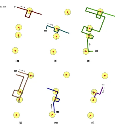
Table 1 shows the results of the first experiment that found avoidance patterns in 6 of 21 trajectories, with the respective global confidence.
Figure 10shows the avoidance patterns for trajectories in Table1. Figure10(a) shows trajectoryt7that intersects only the region of interest of target object 2, and Fig.10(b) shows trajectory t13 that intersects only the region of in-terest of target 1. Both are cases of strongavoidance be-cause the trajectories crossed the respective confidence in-cremental region. Figure10(c) shows trajectoryt18, which
intersects all 4 regions of interest. For target objects 0, 1, and 2, it also intersects the confidence incremental region, therefore, getting a local confidence asstrong. Because this trajectory does not intersect the confidence incremental
re-Table 1 Result of the first experiment considering 20 meters as the radius of the target object, 80 meters for the buffer of the region of interest around the target object, and 8 meters as the minimum length for the subtrajectory directed to the target
Tid Global confidence
t7 1
t13 1
t18 0.875
t21 0.5
t15 0.333
t11 0.25
gion of the target object 3, it has aweaklocal avoidance at this point and, therefore, the global avoidance confidence is (1+1+1+0.5)/4=0.875.
Figure10(d) shows trajectoryt21, which intersects 3 re-gions of interest, all withweaklocal confidence, since there was no valid intersection of any confidence incremental re-gion. This trajectory intersects the region of interest of tar-get 1 twice. For the first time, it does not have any subtory directed to the target. The second intersection of trajec-toryt21 with the region of interest of target 1 had a subtra-jectory directed to the target that was long enough, but after that the trajectory did not intersect the confidence incremen-tal region.
Trajectoryt15, shown in Fig.10(e), presents onestrong local avoidance considering the target 0. In relation to the target 1, the local avoidance isnone, since the trajectory in-tersects the target object. In relation to the target 3, the lo-cal avoidance is alsonone, i.e., there is no avoidance since the trajectory intersects the region of interest but it has no subtrajectory moving in direction to the target with a valid length. Therefore, the global confidence for this trajectory is 1/3 (0,333), having one strong avoidance and intersections with three regions of interest.
Finally, trajectoryt11, shown in Fig.10(f), intersects the region of interest of the target objects 0 and 1, and has one
weaklocal avoidance in relation to target 1 and no avoidance in relation to target 0, because the subtrajectory moving to the target was less than 8 m when the trajectory finished.
For this dataset, a total of 11 avoidance patterns were computed for all trajectories.
5.2 Experiment II—pedestrian trajectories
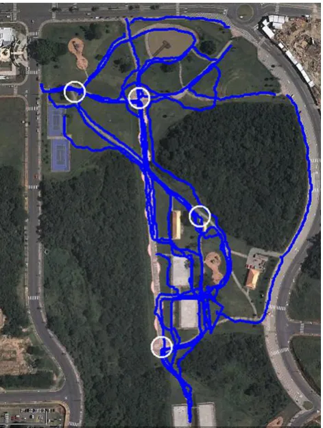
The second dataset is a set of 17 pedestrian trajectories col-lected at the Germania park in the city of Porto Alegre, considering four monitoring regions located on the crossing paths of the main routes in the park. Differently from the car trajectories that follow a road network, pedestrians may follow any directions anywhere. Although there are a few main routes, the objects move in aleatory ways in the park, therefore, these trajectories present characteristics very dif-ferent from car trajectories. Indeed, the speed that a pedes-trian moves may affect the density of the points, since the path followed by a pedestrian during 15 minutes, for in-stance, will be much shorter and denser than a car travel-ing in a highway durtravel-ing the same time period. As the GPS for the pedestrians was configured as for the car trajectories, i.e., the collection of a point every one second; this trajectory dataset is much denser than the previous one.
In this experiment, we considered 10 meters as the radius of the target object and 40 meters as the buffer of the region of interest, simulating a reasonable distance for a pedestrian to identify a camera and then to choose a change on her/his
Fig. 11 Pedestrian trajectories in a park
Table 2 Result of the pedestrians experiment considering 10 meters as the radius of the target object, 40 meters for the buffer of the region of interest around the target object, and 4 meters as minimum length for the subtrajectory directed to the target
Tid Global confidence
t7 0.667
t6 0.5
t8 0.5
t4 0.167
path. We used 4 meters as the minimal length for the subtra-jectory directed to the target.
Figure11shows the visualization of these trajectories in Google Earth. The circles represent the monitoring regions defined as the target objects. After running the algorithm, eight avoidance patterns were found. Table2shows the re-sult of the avoidance patterns of these trajectories, with its respective global confidence.
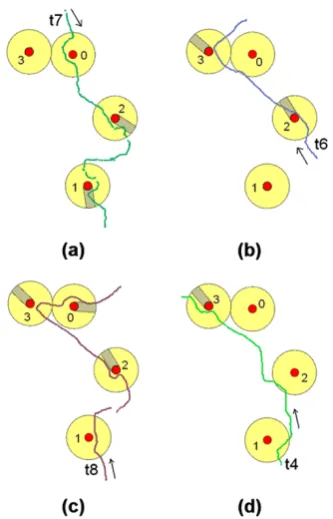
Among the trajectories with avoidance patterns, trajec-toryt7had the highest global confidence. As can be seen in Fig.12(a), this trajectory avoided the target objects 1 and 2
withstronglocal confidence. The global confidence was
Fig. 12 Some pedestrian trajectories
directed to the target with a valid length. Additional exper-iments have demonstrated that when we use 2 meters for the minimal subtrajectory length directed to the target; the global confidence for this trajectory becomes maximal.
In trajectoryt6(Fig.12(b)), we identify one case ofweak local avoidance, in relation to the target object 3, and one
strong local avoidance in relation to the target object 2.
This trajectory intersected the region of interest of target ob-ject 0, but has no subtraob-jectory directed to the target with 4 m length to characterize an avoidance. Then no avoid-ance was identified in relation to this target. This trajectory does not intersect the region of interest of target 1. There-fore, the avoidance level for the whole trajectory resulted in (1+0.5+0)/3=0.5.
Trajectory 8, shown in Fig.12(c), intersects the four re-gions of interest but in relation to the target object 1 there is no valid subtrajectory directed to the target. Considering the targets 2 and 3, the trajectory does not intersect the con-fidence incremental region, receiving the value weak (0.5) as local avoidance. In relation to the target object 0, a strong avoidance has been identified because the trajectory satisfies all avoidance conditions.
In Fig.12(d), trajectory 4 intersects three regions of in-terest, but in relation to the target objects 1 and 2 there is no subtrajectory directed to the target with the minimal length of 4 m, and hence has no avoidance with these tar-gets. A weak avoidance exists with respect to the target object 3. The avoidance for the whole trajectory is then (0+0+0.5)/3=0.167.
Although in this paper we have shown the results of a few experiments on two datasets, we have performed more experiments and the results show that the algorithm cor-rectly finds the existing avoidance patterns. Of course, the parameters—length of the buffer around the target object to define the region of interest, and the minimal length of the trajectory directed to the target—are very important and should be defined according to the specific application in hand.
6 Discussion
In this section, we present a discussion on the parameters of the proposed algorithm and an analysis of its complexity.
As in most algorithms, the choice of the values for the parameters is an important issue. First, the application do-main should be considered. For instance, in the case of car trajectories in a city (i.e., in a road network), the trajectories are limited by the streets and, as a consequence, the choice of the parameters is facilitated. The size of the buffer of the region of interest and the length of the subtrajectory directed to the target should be defined considering that inside the re-gion of interest there should be a distance greater than the minimum size of the subtrajectory directed to the target be-fore the last crossing road, such that if the trajectory turns on that crossing road the avoidance will be detected. Consider-ing this heuristic and knowConsider-ing that the average length of the blocks in the region of experiment 1 was about 70 meters, and that the position of the target objects is in the middle of the blocks, we defined the buffer of the region of interest as 80 meters. To evaluate other values, we executed the same experiment with two other sets of parameters. First, we kept 80 meters as the buffer of the region of interest and we in-creased the minimum length of the subtrajectory directed to the target from 10 to 20 meters. There was no modification in the results. The same occurred with 30 meters as the min-imum size of the subtrajectory directed to the target. This happens because the trajectories are constrained by the road network.
Algorithm complexity, in the worst case, considering the existence of an R-Tree index andT trajectory points andN target objects, isO(TLogN ).
7 Conclusion and future work
Trajectory data are becoming more and more common in daily life. Several works have been developed to extract interesting information and knowledge from these data, as well as trying to infer the behavior of the moving ob-ject. Most works have focused on the common behavior of groups of trajectories of different moving objects.
In this paper, we contribute to advance trajectory data analysis one step forward proposing a novel work to iden-tify avoidance behavior in trajectories. Our work identifies avoidance behavior of individual objects in relation to ex-isting static targets that could be security cameras, police offices, or police controllers, and so on.
The proposed method may be useful in several applica-tion domains like the monitoring of prisoners in semi-open (prerelease) level, traffic management, and security control. As we use raw trajectory data, without considering se-mantic information, the proposed heuristics cannot know if a trajectory deviated the target with the unique intention to avoid it, or if it is the normal path of the moving object. However, this method may help users of different applica-tions to investigate these trajectories.
At this point, we have not considered any semantics to provide more information about the avoidance patterns. However, as future ongoing work, we are investigating new measures to ensure if an avoidance was intentional or forced by an event, like a blocked street, therefore, reducing false positives.
Acknowledgements The authors acknowledge the Brazilian agencies CNPq (project 481055/2007-0) and FAPESC (project CP005/2009), the European Project MODAP, and the Italian agency CNR—Short Term Mobility Program, for the partial support to this research.
References
1. Agrawal R, Srikant R (1994) Fast algorithms for mining associ-ation rules in large databases. In: Bocca JB, Jarke M, Zaniolo C (eds) VLDB. Morgan Kaufmann, San Mateo, pp 487–499 2. Alvares LO, Bogorny V, Kuijpers B, de Macedo JAF, Moelans
B, Vaisman A (2007) A model for enriching trajectories with se-mantic geographical information. In: ACM-GIS. ACM Press, New York, pp 162–169
3. Andersson M, Gudmundsson J, Laube P, Wolle T (2008) Re-porting leaders and followers among trajectories of moving
point objects. GeoInformatica 12:497–528. doi:10.1007/s10707-007-0037-9
4. Baglioni M, de Macêdo JAF, Renso C, Trasarti R, Wachowicz M (2009) Towards semantic interpretation of movement behav-ior. In: Sester M, Bernard L, Paelke V (eds) AGILE conference, lecture notes in geoinformation and cartography. Springer, Berlin, pp 271–288
5. Bogorny V, Kuijpers B, Alvares LO (2009) ST-DMQL: a seman-tic trajectory data mining query language. Int J Geogr Inf Sci 23:1245–1276
6. Cao H, Mamoulis N, Cheung DW (2006) Discovery of collocation episodes in spatiotemporal data. In: ICDM. IEEE Comput Soc, Los Alamitos, pp 823–827
7. Dodge S, Weibel R, Lautenschutz A (2008) Towards a taxonomy of movement patterns. Inf Vis 8:240–252
8. Giannotti F, Nanni M, Pinelli F, Pedreschi D (2007) Trajectory pattern mining. In: Berkhin P, Caruana R, Wu X (eds) KDD. ACM Press, New York, pp 330–339
9. Gudmundsson J, van Kreveld MJ (2006) Computing longest du-ration flocks in trajectory data. In: de By RA, Nittel S (eds) GIS. ACM Press, New York, pp 35–42
10. Hägerstrand T (1970) What about people in regional science?. Pap Reg Sci 24(1):6–21
11. Kim DJ, Park KH, Bien Z (2007) Hierarchical longitudinal con-troller for rear-end collision avoidance. IEEE Trans Ind Electron 54:805–817
12. Laube P, Imfeld S, Weibel R (2005) Discovering relative motion patterns in groups of moving point objects. Int J Geogr Inf Sci 19(6):639–668
13. Laube P, van Kreveld M, Imfeld S (2005) Finding REMO: de-tecting relative motion patterns in geospatial lifelines. Springer, Berlin
14. Lee SW, Lee BH, Lee KD (1999) A configuration space approach to collision avoidance of a two-robot system. Robotica 17:131– 141
15. Liu YH, Shi CJ (2005) A fuzzy-neural inference network for ship collision avoidance. In: Proceedings of 2005 international confer-ence on machine learning and cybernetics. IEEE Comput Soc, Los Alamitos, pp 4754–4754
16. Nedevschi S, Bota S, Tomiuc C (2009) Stereo-based pedestrian detection for collision-avoidance applications. Trans Intell Transp Syst 10:380–391
17. Ong R, Wachowicz M, Nanni M, Renso C (2010) From pattern discovery to pattern interpretation in movement data. In: Fan W, Hsu W, Webb GI, Liu B, Zhang C, Gunopulos D, Wu X (eds) ICDM workshops. IEEE Comput Soc, Los Alamitos, pp 527–534 18. Palma AT, Bogorny V, Alvares LO (2008) A clustering-based
ap-proach for discovering interesting places in trajectories. In: ACM-SAC. ACM Press, New York, pp 863–868
19. Rocha JAMR, Times VC, Oliveira G, Alvares LO, Bogorny V (2010) DB-SMOT: a direction-based spatio-temporal clustering method. In: IEEE conference of intelligent systems. IEEE Press, New York, pp 114–119
20. Shandy S, Valasek J (2001) Intelligent agent for aircraft collision avoidance. In: Proceedings of AIAA guidance, navigation, and control conference. American Institute of Aeronautics and Astro-nautics, Washington, pp 1–11
21. Suh SH, Bishop AB (1988) Collision-avoidance trajectory plan-ning using tube concept: analysis and simulation. J Robot Syst 5(6):497–525