(UDC: 616.314-77)
Three-dimensional finite element stress analysis of SKY implant system
M. Kalanović1*, N. Zdravković- Petrović1, M. Milošević2, D. Nikolić2, N. Zdravković3, N.Filipović2,4,5 and M. Kojić2,5,6
1Medical Faculty, University of Kragujevac, 34000 Kragujevac, Serbia [email protected]
2Bioengineering Research and Development Center, BioIRC, 34000 Kragujevac, Serbia [email protected]
3Faculty of Information Technology, 11000 Belgrade, Serbia [email protected]
4Faculty of Mechanical Engineering, University of Kragujevac, 34000 Kragujevac, Serbia [email protected]
5 Harvard School of Public Health, Harvard University, 02115 Boston, USA [email protected]
6 Department of Nanomedicine and Biomedical Engineering, University of Texas Medical Center at Houston,
1825 Pressler Street,Houston, TX 77030, U.S.A.
*Corresponding author
Abstract
The objective of this study was to evaluate the stress on the cortical bone around few body dental implants using SKY system components with different angled abutments position. These angled abutments have been especially developed for primary structures to allow fast fabrication of occlusal screw-retained temporaries for immediate treatment of patients. Stress levels on these implants were analyzed through finite element analysis. The results showed displacement and effective stress distribution for SKY implants with 90 and 35 degrees position inside jawbone. The 35 degree angled type of implant generated lower von Mises stress in the cortical bone under normal loading of 100 N in comparison with 90 degree angled implant under 50 N loading. The study performed showed the importance of dental implant angled position on the occlusion load transfer mechanism. It was concluded that the high stress gradients can be avoided by different angle position of implants, which can provoke the implant surrounding bone tissue fracture.
Key words: Dental implant; Implant-jawbone interaction; Angled position, Finite element stress analysis.
1. Introduction
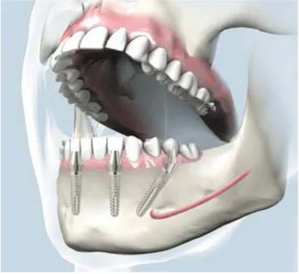
Fig. 1. Orientation of typical implant within the jawbone
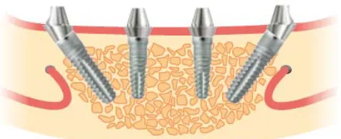
Fig. 2. SKY implants inserted in the local bone
Fig. 3. Cross-section view of SKY implant in the lower jaw
The finite element method (FEM) is a numerical method of analysis for stresses and deformations in structures of any given geometry. The structure is discretized into the so called ‘finite elements’ connected through nodes. The type, arrangement and total number of elements affect the accuracy of the results. The FEM has become one of the most successful engineering computational methods and most useful analysis tool since the 1960s (Ergatoudis et al. 1968, Przemieniecki 1969).
In this study we examined SKY implants which are angled with normal 90 and 35 degrees (Fig.3). The FEM is used to compare stress distribution in jawbone around implant for different loading forces.
2. Methods
2.1 Finite element formulation
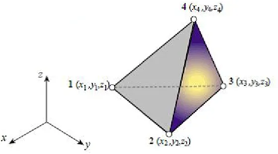
We used linear tetrahedron finite element (Fig. 4) where displacement field over the tetrahedron element is defined by the three components ux, uy and uz. These displacements are linearly
interpolated over the element from their nodal values
1 11 12 13 14 1
2 2 21 22 23 24
3 3 31 32 33 34
4
N
u u u u
u
N
u u u u u
N
u u u u u
N
(1)
where N1, N2, N3, N4 are the interpolation functions which are simply the tetrahedral coordinates;
Fig. 4. The linear tetrahedron finite element
The internal virtual work can be expressed as (Kojic et al. 2008)
int T T T T
V V
W dV dV
e σ U
B CB UU KU (2)where we have employed the relation for strain components:
1,1 ,1 1 1 1,2 ,2 2 2 1,3 ,3 3 3
1,2 1,1 ,2 ,1 1 2 2 1
1,3 1,2 ,3 ,2 2 3 3 2
1,3 1, 1 3 3 1
0 0 ... 0 0
0 0 ... 0 0
0 0 ... 0 0
0 ... 0
0 ... 0
0 N , xx N , yy N , zz N N , , xy N N , , yz , , zx N N u e N N u e N N u e
N N N N
u u
N N N N
u u N N u u e 1 1 1 2 1 3 1 2
1 ,3 ,1
3
... 0
N
N
N N N
U U U U U N N U BU
(3)
from which eT U BT T, and the constitutive relationship σCe; here, e is the strain (used
here in the form of the engineering strain vector), U is the vector of nodal displacements, B is the strain-displacement relation matrix, and C the material constitutive matrix. Clearly, the stiffness matrix K is
T
V
dV
K B CB (4)
and the element internal force Fint is given by the expression Fint KU. The stiffness matrix is symmetric and has dimensions 3N3N (in our case 12 12 ) and the force vector
int
F is of size 3N , int
(int)1, (int)1, (int)1,..., (int)N, (int)N, (int)N
x y z x y z
F F F F F F
F .
The external nodal forces resulting from the pressure on an element surface are calculated by employing again the equivalence of virtual work. A simple approximation for the 4-node tetrahedron element is to calculate the total force as Fp pA (where p is the mean pressure and
2.2 Mesh generation
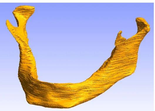
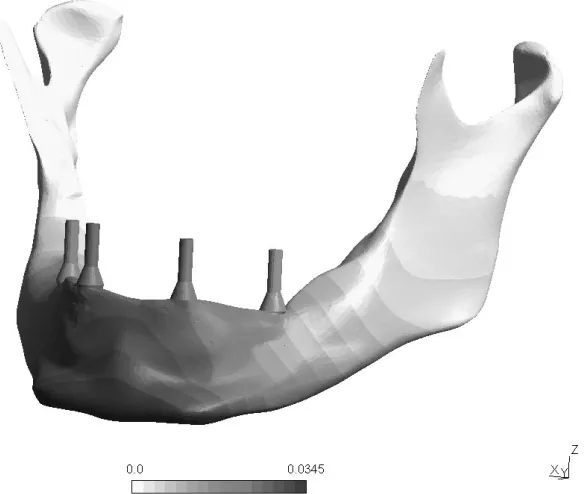
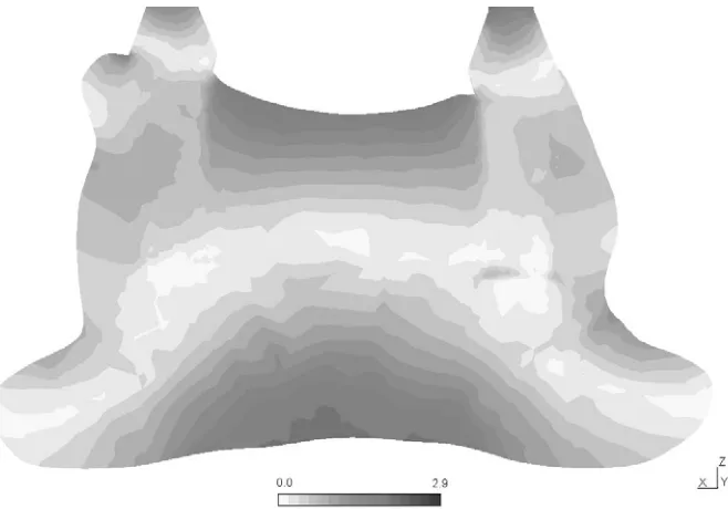
In order to model an angled SKY implant system, we created a 3D FE model with the maxilla, mandible, and all teeth placed in the actual positions. Firstly 3D model of finite element was created by using 3D generation program for jawbone from 3D DICOM CT slices (Fig. 5). After smoothing of the surface boundary the final tetrahedral finite element mesh is shown in Fig. 6. Implant mesh was modeled using dimension from SKY implant system (2010). Simplified models of 35 degrees and 90 degrees implants used in bone modeling are shown in Figure 7. The finite element analysis was performed with in-house program PAK (Kojic et al. 1998). The finite element mesh was composed of 39484 nodes and 178047 linear tetrahedral elements. The implants were assumed to be osseointegrated.
Fig. 5. Jawbone 3D reconstruction from Dicom CT slices
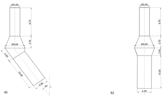
Fig. 7. Simplified models of implants used in bone modeling: a) 35 degrees b) 90 degrees
2.3 Material properties and boundary conditions
All structural materials, cortical and cancellous bone and implants, were considered isotropic and with linear elastic behavior (elastic modulus of the cortical bone and cancellous bone material equal to 13 GPa, implants material equal to 117 GPa, while Poisson’s ratio equal to 0.30 for both the implant and for the bone structures). The load of 100 N was applied on 35 degrees implants and 50 N for 90 degrees implants. The lateral parts of the mandible were rigidly fixed.
3. Results
Fig. 8. Displacement distribution (units mm) for total 4 implants. Two of them in the middle of the model are with 90 degrees while boundary SKY implants are with 35 degrees
Fig. 9. Effective stress distribution (units MPa) at the implant-bone interfacefor the compressive loading configurations. The load of 100 N was applied on 35 degree implants and
Fig. 10. Effective stress distribution (units MPa) for the cross-section along 35 degree implant, loaded by force of 100 N.
4. Conclusions
Finite element analysis has been used extensively to predict the biomechanical performance of various dental implant designs, as well as the effect of clinical factors on the success of implantation. The principal difficulty in simulating the mechanical behavior of dental implants is generating accurate models of the living human bone tissue and its response to applied mechanical forces. This research has been conducted on the comparison of the biomechanical stresses formed in the jawbone for different positions of the SKY implants. The results showed the importance of dental implant position on the occlusion load transfer mechanism. It is shown that the high stress gradients can be avoided by different angle position of implants, in order to prevent the implant surrounding bone tissue fracture.
Acknowledgements The authors acknowledge support of the Ministry of Science of Serbia, grants TR12007 and OI144028; and City of Kragujevac, Contract 1224/08.
Извод
Тродимензионална анализа напона SKY имплант система
Milena Kalanovic1*, Natasa Zdravkovic - Petrovic1, Miljan Milosevic2, Dalibor Nikolic2, Nebojsa Zdravkovic3, Nenad Filipovic2,4,5 and Milos Kojic2,5,6
1Medical Faculty, University of Kragujevac, 34000 Kragujevac, Serbia [email protected]
2Bioengineering Research and Development Center, BioIRC, 34000 Kragujevac, Serbia [email protected]
3Faculty of Information Technology, 11000 Belgrade, Serbia [email protected]
4Faculty of Mechanical Engineering, University of Kragujevac, 34000 Kragujevac, Serbia [email protected]
5 Harvard School of Public Health, Harvard University, 02115 Boston, USA [email protected]
6 Department of Nanomedicine and Biomedical Engineering, University of Texas Medical Center at Houston,
1825 Pressler Street,Houston, TX 77030, U.S.A.
Резиме
Циљ ове студије био је да се одреди напон у кортикалној кости око неколико зубних импланта којикористекомпоненте SKY системаса различитимположајимаабутмената под углом. Ови абутменати су развијени специјално за примарне структуре које омогућавајубрзупроизводњуоклузивнихзавртњевимаподржанимпривременихрешења занепосреднотретирањепацијената. Напонскинивоисуанализираниметодомконачних елемената. Резултати показују расподелу померања и ефективног напона за SKY
анализанапонаметодомконачнихелемената
References
Ergatoudis, I., Irons, B.M., and Zienkiewicz, O.C., (1968), Curved, isoparametric, quadrilateral elements for finite element analysis. International Journal of Solids and Structures, 4(1), 31-42.
Eskitascioglu, G., Usumez, A., Sevimay, M., Soykan, E., and Unsal, E., 2004, The influence of occlusal loading location on stresses transferred to implant-supported prostheses and supporting bone: A three-dimensional finite element study. Journal of Prosthetic Dentistry,
91(2), 144-150.
O'Brien W.J. (1989) Dental Materials: Properties and Selection, Quintessence Publishing, Chicago; London, (ISBN 0867151994).
Przemieniecki, J.S., (1969), Theory of matrix structural analysis. Journal of Sound and Vibration, 10(2), 358-359
Kojic M, Slavkovic R, Zivkovic M, Grujovic N, Filipovic N, (1998) PAK –Program for finite element analysis of construction, Faculty of Mechanical Engineering, University of Kragujevac, 34000 Kragujevac.
Kojic, M. Filipovic, N., Stojanovic, B., Kojic N., (2008) Computer Modeling in Bioengineering – Theoretical Background, Examples and Software, J. Wiley & Sons.