Oke et al. World Journal of Engineering Research and Technology
DEVELOPMENT OF A TWO LEVEL ACCESS CONTROL SECURITY
SYSTEM
*
Oke Alice Oluwafunke, Adedeji O. Titilayo and Fenwa Olusayo Deborah
Department of Computer Science and Engineering, Lautech, Oyo State, Nigeria.
Article Received on 12/08/2018 Article Revised on 02/09/2018 Article Accepted on 23/09/2018
ABSTRACT
Security issue has been a major challenge faced by individuals and
organizations alike. Despite the diverse methods proposed for
protecting lives and properties, security has not yet been achieved due
to cost and a single level access control. Hence, a two level access
control security system is developed to ensure maximum security. In this paper, Radio
Frequency Identification (RFID) security control and password system were utilized to grant
access only to authorized persons. The system consist a RFID card containing the user’s
information which is read by a RFID reader and stored in the microcontroller. The
microcontroller grants access to the door only when the information of the card and the
password is authenticated.
KEYWORDS: Radio Frequency Identification (RFID), password, access control, ATmega328p microcontroller, smartcard, HD44780.
1.0 INTRODUCTION
The advancement in technology has paved way for increase in crime rate, unauthorized
individual easily gain access to an apartment or building through any of the entrance without
permission. This eventually leads to theft of vital information and loss of properties. Different
mechanisms and techniques have been employed to curb this menace by some form of access
control, such as a lock on a car door and a PIN on an ATM system at a bank which are
essentially forms of access control (Verma and Tripathi, 2010; Subramanian et al, 2006). The
revolution of RFID technology has made identification of persons involved in security breach
World Journal of Engineering Research and Technology
WJERT
www.wjert.org
SJIF Impact Factor: 5.218possible. RFID is an automated method of recognizing a person based on an identification
number. It is one of the most important, affordable and reliable method used in developing
and developed countries for security measures (Weis et al, 2004; Phillips et al, 2005). Its data
are separate and distinct because it comprises of personal information (Raheja, et al 2009).
Identification of persons is always important in places like Airports, railway stations,
theatres, companies even home. Companies have implemented access control systems by the
issuance of access badge with radio frequency identification (RFID) to individual employees.
This technique uses electromagnetic fields to exchange data from a tag (like a smartcard) to
an object (a reader) for the purpose of authentication, identification or tracking (Ahasan and
Kingston, 2010; Chawathe et al, 2004). However, the important materials in RFID technology for identification of an individual can be stolen or compromised by an
unauthorized individual; this then necessitated the need for a stronger higher level of security
(Juels, 2006; Xingxin, 2004; Kaushal, et al, 2015) with other security methods such as face
recognition, handwriting, fingerprints, iris, retina, voice etc. Hence, the need for this two-
level access control system of RFID and password technology.
METHODOLOGY
The methods employed in this work include design of circuit diagrams for the system as well
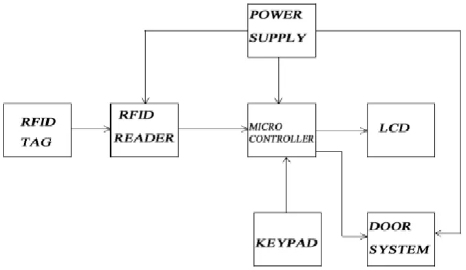
as development of required prototype. The system’s block diagram is shown in Figure 1
and it consists of six components: these are RFID tag (smartcard), RFID reader, Power
Supply, keypad, the Microcontroller, the LCD and the door system (representing the model).
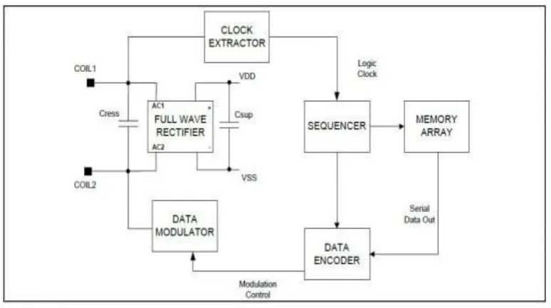
3.0 RADIO FREQUENCY IDENTIFICATION (RFID) TAG
A basic RFID system consists of three components: An antenna or coil, a transceiver (with
decoder) and a transponder (RF tag) electronically programmed with unique information.
RFID is chosen because it is a non-contact system like face recognition system. The radio
frequency identification tag used was a passive tag (in form of a smartcard). The smartcard
contains a large integrated chip which has a unique serial number. The RFID tag was
programmed with the necessary information (e.g name, address, phone number, etc). This
represents the first level access control where the details of the user is captured on a smart
card to be authenticated before access is granted. In this work two tags were used, (though as
many number as required to grant access can be used) one is the master card that was used to
register the other card (or cards). Figure 2 shows a block diagram of a passive RFID tag.
Figure 2: Passive RFID Tag.
3.1 RFID Reader
The EM-18 RFID Reader used is one of the most commonly used modules for Radio
Frequency Identification tasks because of its characteristic which includes Low Cost, Small
Size, Low Power Consumption and Easy usability. It can be directly interfaced with
microcontrollers using Universal Asynchronous Receiver Transmitter (UART)
communication. EM-18 RFID Reader is energized and reads the information on the RFID
Tag as soon as it is brought within the field of the Reader’s EM and gives output via TX
terminal. The reader reads the registered master card first after which the second card (or
3.2 Keypad
The keypad is the second level access control of this work through which password are
entered. It is a 3 by 4 matrix keypad for manual input to the system. It is used either to input
password for registration or verification process. This second level access control is to provide a more secure and efficient control in the event of clone smartcard.
3.3 The Microcontroller
ATmega328p microcontroller was used due to the various features it provides with respect to
the number of digital and analogue inputs the system requires; a factor which helps to
determine the minimum number of inputs and outputs (I/O) that the chosen microcontroller
must have and the extent of need of an internal analogue to digital converter module. The size
of program memory storage, the number of interrupts and timer circuits as well as the
magnitude of clock frequency required. The output of the EM-18 RFID reader which is
equally the RFID tag verification and the password verification process serve as input to the
microcontroller. The ATmega328 is programmed to match the tag ID with the code’s ID, if
the result is true, it produces an output that controls the switching of the relays via the
transistor-relay switching stages, which switches power to the dc motor used in the sliding
door.The relay is switched on when the microcontroller gives a HIGH output. A base resistor
is required to ensure perfect switching of the transistor in saturation. The diode protects the
transistor from back emf that might be generated since the relay coil presents an inductive
load.
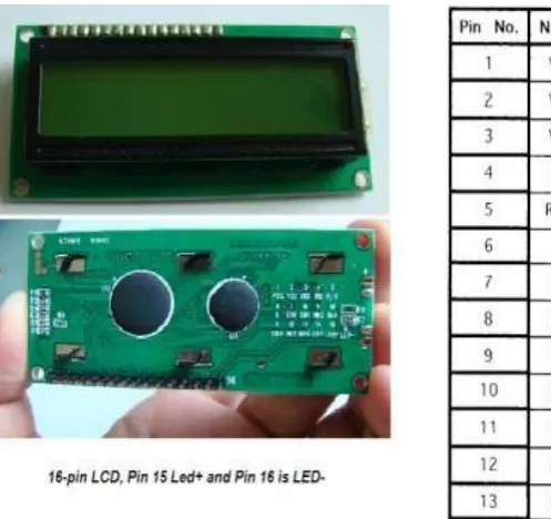
3.4 Liquid Crystal Display
The operating status display stage was implemented using the HD44780 based 16x2
alphanumeric liquid crystal display (LCD) which is cheap, consume less power and can
display characters. The LCD functions as the display section of the system, it displays the
process being carried out and the next instruction. Figure 3 shows the picture of the LCD
used with the pin description. All HD44780 based character LCD displays are connected
through 14 pins: 8 data pins (D0-D7), 3 control pins (RS, E, R/W), and three power lines
(VDD, VSS, VEE). Some LCDs have LED backlight feature that helps to read the data on the
display during low illumination conditions. So they have two additional connections (LED+
Figure 3: LCD and its pin configuration.
3.5 Model Door
The model door employed in this system is used for access granting or denying, because an
access control system is not complete if there is no form of restriction in the whole system.
The sliding door operates using an electric motor relay, this converts electrical energy in form
of electrical signals from the microcontroller into mechanical energy.
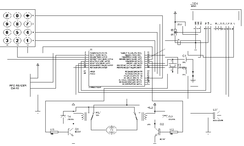
3.6 Power Supply
For this particular design, the power supply that employs the use of the voltage regulator IC
78L05 was used. Herein, a regulated dc voltage is obtained from the mains 220VAC. A step
down transformer is used to step down the 220VAC to 12VAC. The 12VAC is rectified to
obtain a 5V dc voltage required to power the digital circuitry. The unregulated rectified 12V
Figure 4: RFID Circuit Diagram.
4.0 System Operation
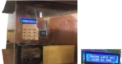
Figure 5 shows the model for the system. The power to the system is turned on and the
system displays a welcome address on the LCD as shown in Figure 6, this is the system’s
readiness for registration. The first stage is the registration process, the user swipes the master
card along the EM-18 RFID reader which prompts a message for the pin mode and to enter
the master card password, a four digit word is entered as programmed. The second card (or
other cards) is (are) then registered by swiping them over the RFID reader, a four digit
password is also requested for; which after being supplied ends the card registration process.
The next stages are the identification, verification and access stage. To access the door, the system starts by displaying “Welcome, card please” on the LCD after which the user swipes
the card over the RFID reader. If the card is a registered card, the system requests for user
password, which the user must supply. If password tallies with one of the registered
password, the door opens for three seconds and then closes but if not access will be denied.
Similarly, if the card is not registered no action will be taken by the system meaning access
will be denied. Figures 7 -12 show extract of the registration, identification, verification and
Figure 5: RFID Model.
Figure 6: The system is ready for registration.
Figure 7: The card swiped along the reader. Figure 8: Master card password required.
Figure 9: Swipe the unregistered card. Figure 10: Enter new password. Liquid Crystal Display
Password Keypad
Door RFID Reader
5.0 CONCLUSION
The design and implementation of the RFID based security control and access system was
done with consideration of some factors like availability of components and research
materials, economic application, design economy, compatibility and portability, efficiency
and also durability. The performance of the work after test met design specifications.
However, the general operation of the construction and performance is dependent on the user
who is prone to human error. The construction was carried out to make maintenance and
repair easy for user in case of any system breakdown. The access control unit involved
research in both microelectronics and embedded system design. The project has really
brought to light digital and practical electronics which is one of the major challenges that
shall be met in the field of engineering now and in future.
REFERENCES
1. AhasanK. and P. Kingston: IEEE Paper On “RFID Applications: An Introductory and Exploratory Study”, 2010; 7(3): 1-7.
2. Chawathe S., Krishnamurthy V., Ramachandran S., and Sarma S., Managing RFID data.
In Proc. VLDB, 2004; 1189–1195.
3. Juels A., RFID Security and Privacy, A Research Survey, IEEE Journal On Chosen Areas
In a Computing, 2006; 24(2): 381–394.
4. Kaushal G., R. Mishra, N. Chaurasiya, P. Singh, RFID Based Security and Access
Control System Using Arduino With Gsm Module, IJEEE, 2015; 2(2), E-ISSN:
1694-2310, P-ISSN: 1694-2426.
5. Phillips T., KarygiannisT. and Kuhn R., "Security Standards for the RFID Market. IEEE
Security standards and Privacy, 2005; 3(6): 85-89.
6. Raheja J. L., S. Nayak and A. Gupta, RFID Based Networked Gate Entry Control System
(GECS), IJCNC, 2009; 1(3).
7. Subramanian V., P. Chang C., Huang D., J. B. Lee, S. E. Molesa, Redinger D. R., and S.
K. Volkman, All-Printed Rfid Tags: Materials, Devices, And Circuit Implications", VLSI
Design, CRC Press, 2006.
8. Verma G. K. and P. Tripathi, A Paper on a Digital Security System with Door Locks
System Using RFID Technology, IIT Allahabad, 2010; 5(11): 6-8.
9. Weis S. A., Sanjay Sarma E. and Rivest R. L., A Paper On “Security And Privacy
10.Xingxin Gao, An approach to security and privacy of RFID system for supply chain,
E-Commerce Technology for Dynamic E-Business, IEEE International Conference, 2004;