Material Specific Product Design Analysis
for Conditional Failures – A Case Study
S.N.Vijayan*, M.Makeshkumar*
*Assistant Professor, Department of Mechanical Engineering, Karpagam Institute of Technology, Coimbatore, INDIA
e-mail:[email protected], Tel + 91 99427-66041
Abstract
Rotary kiln support roller and shaft are located under the kiln, which is in contact with the kiln ring. In recent years, it is estimated that many roller shaft failure occurs due to continuous loading condition that prevails in the industries due to inevitable facts. The shaft is affected by high stresses with respect to kiln load on the roller. A thorough insight over literature reports that it can be avoided by proper design and supportive remedial measures of the roller and shaft well before manufacturing. In the present study, the analyses of roller and shaft have been done using Finite Element Method. The loading position is varied according to kiln ring and the support roller for the actual working condition. The load calculations and analysis of the shaft are done by analytical and finite element method respectively. The results are compared between the existing and the new design by changing design metrics and material prospects.
Key words: Rotary Kiln, Shaft, Stress, FEA 1. Introduction
The major accessories of Rotary kiln namely the support roller and shaft are well seated under the kiln which is turning sophisticated by the kiln ring. Literature reveals that in recent years many roller shaft failure occurs due to continuous loading condition. At this juncture, it is highly necessitiated that theories and researches has to be focused highly on design of the support roller. M.J.Reid et.al has investigated the external causes of the shaft failure in the sugar mill operation and have reported on the analysis carried over to the roll shaft failure. B.S.Dhillon et.al have exemplified upon the fatique reliability evolution of the kiln roller to have a selfbiassed approach on the impact strength and its illeffects. C.E.Thornton et.al have studied the effect of loads on EN8 material by consideration of relevant factors. Similarly the yield flow and creep behaviours of annealed EN24 steel under combined stress conditions was studied by A.Shelton et.al. Furthermore, the study dealt with the analysis of failure in shaft by analytical and finite element analysis methods which revealed that the stress-strain-time behaviour of the material under complex stress.
2. Methodology
The failure of the shaft is very common due to the heavy loads applied on roller. There are different methods availabe to increase the life of the shaft. As reported in literature, the commercial alternative methods are
o By aligning the kiln shell very accurately. o Ensuring smooth operation by even loading.
o Controlling the reverse motion of the kiln shell during emergency. o By changing the design and material of the shaft.
Figure 1. Methodology
The smooth operation cannot be ensured because the loading is very uneven for the operation which the kiln is meant for. The controlling of reverse motion is difficult to achieve due to the weight of the kiln itself and the hydraulic drive system which is used to rotate the kiln. Hence in close adoption to the prevailing technocratic conditions adoption of the aforesaid research hypothesis of changing the design and material of the shaft would be highly optimal for the envisaged condition.
Data Collection
Design and modeling of the existing roller – shaft assembly
Analyses of roller assembly by FEA
Validation of analysis results
Selection of newer material and design
Analytical calculation of stresses in shaft
Analytical method
Analyses of roller assembly by using FEA proposed material and design
alternates
newer material and supplement changes in design. The change in design and substantial material of the shaft orients towards development of a suitable component viz.shaft for the applicable system namely Rotary kiln.
Fortunately upon comparison of the existing material (EN8 mild steel) and the present system of rotary kiln design has to be effectively replaced by suitable alternatives.
4. Design metrics
Let the maximum load acting on the shaft to be X mt and the diameter of the shaft to be Y mm and the span of the shaft to be Z mm. The specification of the rotary kiln used for carbonization is considered for the characteristic developments and further analysis of present research study.
X = 180 mts
Y = 80 mm
Z = 700 mm
The properties of the EN8 shaft material are as listed in table: 1. Table 1. EN8 material properties
Compositional element Percentage of composition % Young’s modulus N/mm2 Poisson Ratio C Si Mn P S Fe 0.40 0.25 0.80 0.015 0.015 Remaining
2.05E5 0.3
To have an effective validation of the current study the pros and cons of the existing material and design was thoroughly made over. Also to forecast the nature and characteristic behaviors of the new material and considerable design, the existing system was subjected to analytical and FEA methods. Furthermore a detailed comparison upon the existing design metrics and the proposed alternative was taken over.
5. Results
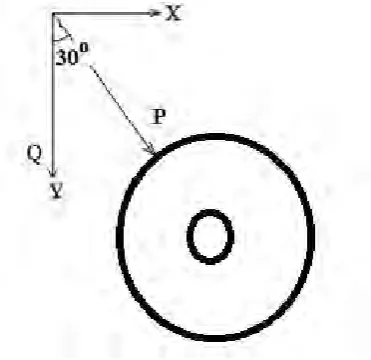
Figure 2.Exemplifies the load acting on
Support roller and shaft
Total load acting on rollers P = 180 Ton
= 180000*9.81 = 1765800.5N
Load per roller = (1765800/4)*cos 30 = 382306.9N
5.2 Product Design Analysis
5.2.1. Existing design: The initial crack usually follows a line at 90 degree to the shaft axis which indicates that the direction of the primary stress is due to the bending of the shaft and not because of torsion. The shaft material was analyzed and was found to be well distributed with in specification limits of applied node. For existing design of the shaft, the calculation is done by analytical method using bending equation and the maximum stress obtained is 46576.35N/cm2.The Finite Element Analysis results for the existing design are as shown in figure.3 & 4.
Figure 3.The stress induced on Z-axis
Figure 4.The stress induced on X-Y axis
Figure.4.exemplifies that the stress induced for existing design of the shaft approximates to 44276N/cm2 on X-Y axis.
5.2.2. Proposed Design: The review of literatures and therefore coined research objective encourages the change of material from EN-8 to EN-24. It is globally renowned that EN-24 has high tensile strength and withstands heavy load under critical conditions of envisaged operations. The properties of EN24 are as showcased in table.2.
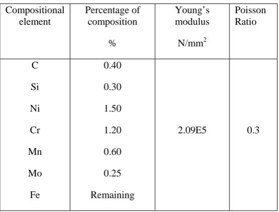
Table 2. EN24 material properties
Compositional element
Percentage of composition
%
Young’s modulus N/mm2
Poisson Ratio
C
Si Ni Cr Mn
Mo Fe
0.40
0.30 1.50 1.20 0.60
0.25 Remaining
2.09E5 0.3
5.3 Design for Material Attributes
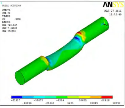
Figure 5. Maximum bending stress on Y-Z axis for EN24 material
Figure 6. Maximum bending stress on Y-axis for EN24 material
From figure.5.it is observed that the stress induced in the shaft is observed to be around 49008 N/cm2 on Y- Z-axis. Similarly figure.6.exemplifies that the stress induced on the shaft is observed to be around 48915N/cm2 on Y- axis.
The design metrics ie, diameter of the shaft is calculated for the applied load by using bending equation. The optimal diameter of the kiln shaft is approximated to 120mm as a result of the updation.
5.4 Proposed Product Design
Figure 7. Maximum bending stress on X-Y axis for proposed design
Figure 8. Maximum bending stress on X-axis for proposed design
The figure.7.indicates the analyzed values of a redesigned shaft on X-Y axis. The stress value, extracted from the analyzed result observed is around 13403N/cm2.
Similarly figure.8.indicates the analyzed values of a redesigned shaft on X-axis. The stress value, extracted from the analyzed result observed is around 13839N/cm2.
6. Life Prediction
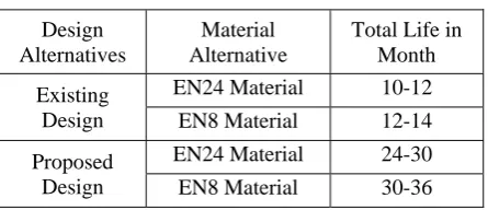
Table 3. Life Predictions
Design Alternatives
Material Alternative
Total Life in Month Existing
Design
EN24 Material 10-12 EN8 Material 12-14 Proposed
Design
EN24 Material 24-30 EN8 Material 30-36
From the table.3.it is clear that the maximum permissible life can be attained through an alternative design for the EN8 material, EN24 material could not sophisticate the present application as the increment in diameter of the shaft and life of the product are proportionate. Hence it is supportive that by the adopted design metrics, the change in life is doubled in due consideration of the external factors associated.
7. Discussion
By the results obtained, it is clear that the change of material from EN-8 to EN-24 gives a marginal reduction in stress due to the change of property of the material. It is also clearly evident that the change of proposed material does not give adequate strength to take the load when compared to the alternative method of changing the dimension of the shaft. By changing the design of shaft, results in the reduction of the stress by a high margin. This clearly evident that the calculations carried over by both analytical method and finite element analysis hence yielded better results.
8. Conclusion
There are many external causes of shaft failure which can be eliminated by changing the whole design of the kiln but it is not possible and it is very costly and time consuming. The change in the material results is very marginal reduction in stress and it may cause failure at any stage due to the operation of the kiln. The change in the dimension of the shaft will give high strength to shaft to carry the load and by which the life of the shaft is doubled. Therefore, adoption of change in material prospects and design prospects is a recommendable factor in due consideration of the operable conditions and sustaining parameters.
Acknowledgement
The authors acknowledge the contribution of M/s. Genuie Shell Carb (pvt) LTD, Coimbatore, Tamilnadu.
References
[1] M.J.Reid. ‘Analysis of the causes of recent roll shaft failure in natal sugar mills’ proceeding of the south African sugar technologists’ association-june1988.
[2] B.S.Dhillon, Xuejun LI,Yiping SHEN. ‘Fatigue reliability Evaluation of the Kiln roller’.
[3] C.E.Thrnton, E.R.Wallach. ‘Impact strength of EN8 steel diffusion bonds’ journal of materials science 18(1983)1433-1442. [4] S.N.Shahabi, A. Shelton. ‘The Yield, flow and creep behavior of annealed EN24 steel under combined stress’ journal mechanical
engineering science, march E 1975.,Vol17No2 .
[5] C.Boller: Materials Data for Cyclic loading, Part B: Low –Alloy steels, materials Science Monographs, 42B, Elsevier, 1987. [6] B.S.Dhillon, Xuejun LI,Yiping SHEN. ‘Fatigue reliability Evaluation of the Kiln roller’,2009.
[7] N.Sachs. ‘Failure analysis of mechanical components’ ,1993.
[8] ZHU Huai-Liang. ‘Dynamic analysis of a spatial coupled Timoshenko rotating shaft with large displacements’, applied mathematics and mechanics, English Edition,Vol.23,No 12,Dec 2002.
Biographical notes