METHODOLOGY FOR CONFIGURING AN INTELLIGENT NETWORK EXPERT
SYSTEM [AINES] USING THE EXAMPLE OF AN ELECTROCHEMICAL
DIMENSIONAL PROCESSING MACHINE
Davletbaev A.S., Kulikov G.G., Startcev Y.V. Ufa State Aviation Technical University, Ufa, Russia
E-Mail: [email protected], [email protected], [email protected]
Abstract: The article deals with the configuration of the expert system for working with electrochemical equipment. The process of
electrochemical dimensional processing (EDP), its main parameters and the influence of conditions on their change are considered. The method of setting up the system for working with the EDP machine is given and an approximate variant of the result of the system operation is considered
1. Introduction
In modern production, especially in such complex high-tech areas as engine-building, advanced developments in the field of materials science are used. New types of metal alloys are being developed, which are used in the most severe conditions. The details are being introduced, the production of which is a huge number of technological operations. Accordingly, the cost of manufacturing it increases with each new operation. Especially heavily on its cost is affected by complex technological operations, which require huge accuracy, up to several microns. Accordingly, equipment that can perform such operations with a sufficiently high speed and performance is necessary. One such machine is the EDP machine. The use of electrochemistry makes it possible to process metals with sufficiently good accuracy, roughness and speed, which is achieved due to fine tuning of the equipment. The setup includes several dozens of parameters, each of which is very significant and directly affects the final result. This imposes a great burden of responsibility before the operator-technician (technologist) in the preparation of production, because fine tuning of the equipment, at the moment, is often on the verge of intuition, coupled with extensive experience and numerous works of the technologist. It was to facilitate the routine of the technologist that an automated intellectual network expert system [AiNES] was designed. Thanks to such a system, the commissioning of production will be greatly facilitated, and the technologist's load, in part, will fall on the lightweight technological devices that today surround us everywhere.
2 The process of electrochemical dimensional processing for the formation of GTE turbine blades
2.1. Description of the process of electrochemistry
The process of electrochemical processing is a method for processing electrically conductive materials, consisting in changing the shape, dimensions and (or) roughness of the workpiece surface due to anodic dissolution of its material in the electrolyte under the influence of an electric current [2]
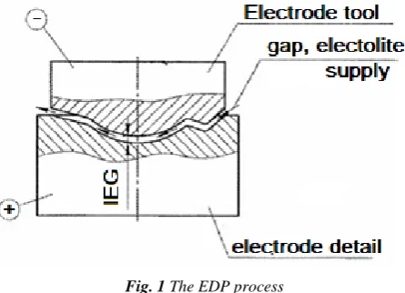
For thinning, it should be added that EDP - dimensional processing is a directed process of dissolving the metal in order to give the workpiece the desired shape and size (Fig. 1). At
EDP electrode tools attach a negative potential, electrode-workpiece is positive. In the space between them, liquid is supplied - an electrolyte, in the medium of which the metal of the electrode-billet is dissolved. In this case, the dissolution of the metal occurs at different rates. The smaller the interelectrode space (the inter electrode gap of the IEG), the faster the metal dissolves. Thus, during the time the rate of dissolution of metal over the entire surface tends to equalize, as a result of which the IEG is aligned along the entire gap, which gives the electrode-workpiece the same shape as the tool electrode. In this case, the dissolution of the electrode-tool itself is so small that this quantity is neglected.
Thus, the shape of the surface of the tool electrode is completely copied onto the surface of the workpiece electrode.
Fig. 1 The EDP process
This process that has become widespread in the manufacture of blades of gas turbine engines (GTE).
In our case, the process of manufacturing GTE blades on EDP machines with vibrations is considered, which is performed on ECM 38.5 machines.
2.2. Описание проблемной области ЭХРО
The problem that must be solved by the technologist is the parameters of the process itself (Figure 2). The cycle of the technological process consists of several stages.
Fig. 2 Cyclogram process EDP
Each stage is important for the correct flow of the process itself and is carefully controlled by the machine's automation. There are the following main stages:
- search for the part coordinate; - exit to the gap processing (Fig. 2 - δ); - active part processing phase. There are additional stages: - outlet to the rinsing gap; - exit to the starting position;
- reperforcing (special operation of bringing the coordinate axis of the drives into the initial synchronous position) of the tool electrode.
zero position (the lower position of the tool electrode) is determined when the electrode is in the nearest position to the detail (Fig. 2 - 5). And the upper position zone is the electrode at the maximum distance from the part. The frequency of the vibration determines the frequency of the working current pulses (Fig. 2-a), as can be seen, the current (Fig. 2 - 3) is fed in the lower position zone, when it gives the maximum impact on the workpiece surface, in the zones "in the middle" between the lower and upper zone the voltage pulse switches its state (on / off), while in the upper position zone the most efficient washing of the metal dissolution zone takes place, during which electrolyte streams carry away the decomposition products and partially cool the working surfaces STI.
When searching for a part, they are guided by the voltage dip (Fig. 2 - 4) at the moment of contact (Fig. 2 - c), which is the evidence of the contact of the part and the electrode. The time interval between the search for the part is called the processing cycle time (Fig. 2 - Tц), so you can see the set of parameters that need to be set in the EDP machine for the correct flow of the process.
2.3. Formulation of the problem
As can be seen from the brief description of the EDP process, there are various parameters that need to be monitored. For the correct operation of the [AiNES] system, it is necessary to correctly configure these parameters and distribute them in groups:
- machine parameters; - detail parameters;
- technological parameters of the process; - parameters of external conditions; - parameters of the result of processing.
It is also necessary to determine which of them are formalized and which are not, determine the limits of their values and the probable values.
In other words, it is necessary to model the parametric model of the EDP process.
Then it is necessary to determine the criteria and methods for estimating the result, which will be obtained at the output of the decision system.
It is necessary to evaluate the efficiency of using the system on the machine ECM 38.5.
3. The solution of the task
3.1. Determination and distribution by groups of parameters of EDP
3.1.1 Machine parameters
For the EDP process for the manufacture of GTE blades in practical applications, the following parameters are determined as a result of the observation, which can be changed by the technologist (in the brackets, the limits for the ECM 38.5 machine):
- min / max voltage produced by the machine (5/65); - max current given by machine (3000A imp); - max positioning accuracy of machine (4 mkm);
- min / max frequency of vibration of the tool electrode (0/50 Hz);
- min / max pressure of the electrolyte, issued by the pump (0.1 / 10 Atm);
- min / max cycle time that the equipment can withstand (1/900 sec);
- min / max speed of the electrode movement that the machine can provide (10/10000 Mkm / s).
These parameters do not directly affect the solution of the system, but are crucial for filtering the results of calculations. If there is a deviation in any parameter, then it is considered that for the given parameters processing cannot be performed on this equipment. It is necessary either to modernize the equipment, because to perform the operation on another machine.
3.1.2 Detail parameters
The parameters of detail refer both to the detail and to the finished part, i.e. is considered in the context of the work object:
a) material of deail (alloy 20X13 was studied);
b) total area of the treated surface (of the order of 50 cm2 on two sides);
c) curvature of the surface (curvature of the standard GTE blade);
d) number of simultaneously processed parties (2); e) stiffness of fixing detail (deviations at loads of 100 kg +/- 10 μm);
The parameters "a" and "c" are unformalized in the presented list, therefore we see the formalization procedure by splitting the parameters into components, if possible, or we make up a categorical dictionary for assigning an individual number and value parameters (necessary for the use and training of the neural network)
For the parameter "a" - detail material, we define: - hardness of the material (126-197 MPa); - specific gravity (7670 kg / m3)
- valence of detail material (4);
- Electrochemical equivalent of the material of detail (1.94 kg / Cl);
For parameter "c" we define the curvature dictionary, the name of the curvature index (value 1).
3.1.3 Process technological parameters
This group of parameters is the required group of parameters that must be transferred to the technologist for setting up the machine. The following parameters are selected:
- processing stress (20 V); - working gap (100 microns);
- vibration frequency of the tool electrode (25 Hz); - number of washing cycles per period (2 times); - washing distance (250 μm);
- pressure, under which the electrolyte is supplied (1.5 Atm);
- duration of the active phase of dissolution (5 sec.); - delay of the beginning of the pulse with respect to the point of the upper position (90 deg);
- phase of the end of the voltage pulse (270 deg);
- speed of electrode movement during the active phase of metal dissolution (0 μm / sec).
These parameters were used during the test processing and are given for the comparative analysis of the work results (they are stored in the database as the set of parameters chosen for operation).
3.1.4 Parameters of external conditions
This group of parameters that cannot be configured programmatically, but can be indirectly changed. They also affect the EDP process. These include:
a) type of operation (complex dimensional shaping); b) material of the tool electrode (stainless steel alloy); c) composition of electrolyte (sodium nitrate 7%, sodium chloride 7%, water 86%)
d) temperature of the electrolyte (25 degrees); e) electrode area (total for both electrodes is 50 cm2)
e) positioning accuracy (5 μm);
Among the presented parameters parameter "a", "b" and "c" do not have a numerical representation. Therefore, we need to formalize them.
For the parameter "b" the formalization is done by splitting the parameter into:
- valence of the electrolyte (4); - viscosity of the electrolyte (2.3 mPas); - electroconductivity of the electrolyte (3.54х10-2
S / m); - density of electrolyte (2.81 g / cm3).
- Electrochemical equivalent of the material of the billet (1.94 kg / Cl);
- Hardness of the material (126-197 MPa); - Specific weight (7670 kg / m3)
For the "a" parameter, a dictionary of operation types is defined, for our case we enter the value type 1.
3.1.5 Results parameters
The expected processing parameters have the same set as the actual processing result. It is during the comparison of these parameters that the success of processing is determined. The list of parameters is as follows:
- processing speed (less than 15 minutes per detail / 12 minutes per detail);
- processing accuracy (maximum deviation 100 μm / max deviation 70 μm);
- Rmax roughness (10 μm / 15 μm); - percentage of defects (0% / 5%).
For parameters in parentheses are specified (set value / value obtained)
3.2. Distribution of parameters in the problem being solved
The groups of parameters considered hereafter are used to configure and train the neural network (Fig. 3). For input parameters are used:
- parameters of detail;
- parameters of external conditions; - parameters of result (expected).
For output parameters, a group is used - process parameters of the process. They are of the greatest interest to the technologist during the setup of the equipment.
At the same time, the result of the operation of the neural network is one resulting set of parameters, which are then fed to the filter algorithm along with the hardware parameters in order to ensure that the process with the parameters found can occur within the constraints of the current machine. Also on this filter pass all the solutions found by the system. It is assumed that this particular machine should perform this operation. If the filter does not miss any of the solutions found, the most appropriate set of parameters is selected and provided to the technologist with a note that the set of parameters is not optimal and has unattainable values.
Fig. 3 Distribution of parameters
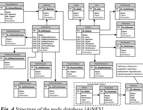
The resulting database for storing all the necessary data is built on the basis of the three main fields of the tables (Figure 4):
- Name- specifies the name of the parameter set (the default date and time of creation)
- Object - the saved serialized parameter object (list of parameters with type and description). The parameter is stored as a binary sequence, the entire class is saved.
Description - the description of the current object.
Also, there are tables in the database for configuring the default values (Figure 4 of the table with the prefixes "Def"). They serve as the basis for the structure of the neural network and determine the minimum necessary set of parameters for the formation of training samples of the neural network.
DefParams PK ID_DefParams Name FK1ID_DefDetailParams FK2ID_DefMachineParams FK3ID_DefResParams FK4ID_DefIniParams FK5ID_DefTechParams FK6ID_Machine Description DefMachineParams PKID_DefMachineParams Name Object Description NeyralNetwork PK ID_NeyaralNetwork Name FK1ID_Machine NN_Object Revision Description ResParams PKID_ResParams Name Object Description IniParams PKID_IniParams Name Object Description TechParams PKID_TechParams Name Object Description User PKID_User Name Object Description Detail PKID_Detail Name Object Description Machine PKID_Machine Name Object Description DefTechParams PKID_DefTechParams Name Object Description DefResParams PKID_DefResParams Name Object Description DefDetailParams PKID_DefDetailParams Name Object Description DefIniParams PKID_DefIniParams Name Object Description History PK ID_History Name FK1 ID_User FK2 ID_Machine FK3 ID_Detail FK4 ID_IniParams FK5 ID_TechParams FK6 ID_ResParams FK7 ID_RealResParams Description ReserveObject PKID_ReserveObject ID_Object Type Description Measure PKID_Measure Name Eval Abbr Group Description RealResParams PKID_RealResParams Name Object Description Parameter PKID_Parameter Name Value Measure Description Object PKID_Object Name Parameters Type Description Serializable Object
Таблица «Measure» содержит единицы измерения параметров сериализуемого объекта
Fig. 4 Structure of the node database [AiNES]
All neural networks after the post-training are stored in the database in the table "Neural Network". Each under its own name is linked to the machine for which it was trained and with the revision number for further optimization and rollback when working with neural networks. The summary entry "History" is the base record of the system. It represents the history of operations and works that were conducted in the system. Data extraction is complex, and the input of new data can be combined and duplicated to speed up the input (auto-substitution mechanisms).
On the side, there is only a table of units of measurements that are stored by a separate branch and synchronized among the nodes to preserve valid consistent results between the nodes of the system.
4. Practical implementation of the system
4.1 The final structure of the artificial neural network
Based on the parameters defined above, we compose a neural network (Fig. 5).
In the design and configuration of a neural network, 26 inputs were assigned to the input, distributed in three groups (as described above). The input groups that were used for the neural network have one additional input, the so-called activation inputs. The use of such inputs (to which only one is fed) favorably affects the overall result. In the first layer (Normalize level), the parameters are normalized in such a way that the output values are given in the range from -1 to 1. This is necessary so that the weights of the neural network during training do not become too large or very small. Accordingly, at the output level (neurons from 27 to 36) perform the reverse operation of converting the values to the allowable range of the final values.
Intermediate layers: the first hidden layer - 53 neurons (26 input * 2 + 1), and the second hidden layer - 107 neurons (53 from the first hidden layer * 2 + 1) - calculated according to Hecht-Nielsen's theorems is assumed equal to 2n + 1, where n is the number of input signals and the number of neurons of the previous layer.
Fig. 5 structure of the neural network for the ECM 38.5
machine
4.2. Using the system in the workshop
Interaction with the system within the workshop (Figure 6) is carried out directly by the technologist. The technologist is authorized in the system by means of an individual login/password. After successful authorization gets access to the system. Then, within the problem of finding a solution, enters the initial parameters (selects the machine, selects the part, enters the initializing parameters and enters the parameters of the desired result).
The system saves the current parameters and forms a search task. Asks the user to confirm the beginning of the procedure for calculating the parameters. After the technologist confirms the beginning of the calculation, the system packs the task and sends it to the network to other nodes [AiNES] via the network of the system ([AiNES] network), where the free nodes of the system (another node [AiNES]) perform the common task and the decision (search decision) returns the result (decision). In turn, in parallel, the system searches for a ready solution in the database (search local DB result) and calculates the solution on the neural network (calculate on neural network), if it is considered ready for use. All results are collected in a single solution pool and filtered.
Fig. 6 time diagram of the system operation
As a result of the filtering, the technologist is provided with a set of several optimally optimal results. The system asks to choose one of them, or enter its own set, after which the whole set of parameters is stored in the database and waits for the input of the real part processing result, after input, to which the neural network can be trained or modified.
This completes one configuration cycle.
4.2. Preliminary results of using the system
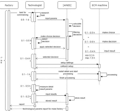
As a result of the conducted experiments, the control measurements of the operations performed by the technologist were made (Fig. 7). The experiments were carried out on the basis of test fixtures, parts and tools. The main purpose of the experiments was the accumulation of data for the training of neural networks. The operating time of one tuning cycle was from one hour to 10.6 hours (considering 1d = 8 hours, working shift).
Fig. 7 time diagram of the commissioning process
blanks that can be spoiled. Given their cost (from 200r to several thousand rubles), the savings becomes obvious.
5. Conclusion
The article discusses the process of EDP, defines the main parameters of the process, the main difficulties in working with this technology. The example shows a method for configuring a neural network for operation in the [AiNES] system, and methods for generating parametric process models are shown. Examples of technological and other parameters that were obtained and used in the tests carried out on the machines ECM 38.5 are shown. An example of a neural network is shown and the algorithm for working with the system is shown, the time indices of the cycle of tuning the machine for processing one part are determined. A comparative analysis of the economy of the enterprise was carried out when using the system, which amounted to saving about 4 cycles of tests on the machine, which saves from 3 hours of work time of the technologist and from 800 rubles on the material of blanks.
Thanks
The author is grateful to Cand. tech. Gantsev Rustem Khalimovich for providing the equipment and consulting, ch. Technologist of JSC ISTC "Iskra" Semashko Andrey Pavlovich for consultations on the technological part of the work on electrochemical machining machines, Head of the electronic automation department of JSC ISTs "Iskra" Gilmetdinov Marat Hammatovich for help in organizing and constructing the test program for ECM 38.5 machines
List of sources used
1. 1. Senthil Kumar K.L. Modeling of metal removal rate in machining of aluminum matrix composite using artificial neural network // Journal of Composite Materials 45 (22), DOI: 10.1177 / 0021998311401083 pp. 2309-2316
2. 2. A. JONES D. A prototype expert system for manufacturing resource planning // I NT. J. COMPUTER INTEGRATED MANUFACTURING, VOL1, NO.3. pp. 165-170
3. 3. A. Macioł Ma cio P. drusik ł • St. Je¸ • Lelito J., New JL, Managing Techniques (2015) 79, DOI: 10.1007 / s00170-015-6860-5 pp. 1733-1745
4. 4. Davletbaev A.S., Startcev Y.V., Kulikov G.G. Development of the Automated Networking Expert System [AiNES] // The 17th International Workshop on Computer Science and Information Technologies CSIT'2015, (Rome, Italy Sep. 22-26 2015) volume 1, pp. 11-15
5. 5. Swingler K. "Applying Neural Networks .A practical G-uide" (translated by Y.P. Masloboev) URL: http://matlab.exponenta.ru/neuralnetwork/book4/3_2.php - (date of treatment: 01/25/2016)
6. 6. Bakhmetova NA, Tokarev S.V. MODELING TECHNOLOGICAL PROCESSES WITH NEURAL NETWORKS [Electronic resource] Modern high technology. - 2008. - No. 2. - P. 139-140 - URL: http://www.top-technologies.ru/en/article/view?id=23277 (reference date: 16.03.2016).
7. 7. D. Tarkhov, "Neural network models and algorithms. Handbook ", Radio Engineering, ISBN 978-5-88070-376-0; 2014
8. 8. MA Bosinzon "Modern CNC systems and their operation". Textbook for the beginning. prof. of education. Academia, 2009 ISBN 978-5-7695-6060-6
9. 9. Andrew S. Tanenbaum, Maarten van Steen. "Distributed systems." Principles and paradigms ". - St. Petersburg: Peter, 2003. - 877 p. - (Classics of computer science). - ISBN 5-272-00053-6.
10.10. Wikipedia, the free encyclopedia, "Electrochemical
machining" URL: https://en.wikipedia.org/wiki/Electrochemical_machining