Real Time Implementation of Vehicular
Ad-hoc Network
Neha G.Gupta¹, Rajesh D. Thakre², Yogesh A. Suryawanshi³
¹ Mtech Student in Department of VlSI Design , Y.C.C.E.,Nagpur ²Professor in Department of Electronics Engineering,Y.C.C.E., Nagpur.
³ Associate Professor in Department of Electronics Engineering, D.M.I.E.T.R, Sawangi (Meghe),Wardha Maharashtra, INDIA
Abstract —Vehicular Ad-Hoc Network or VANET is a form of mobile ad-hoc network. VANET is used to provide communications among neighbouring vehicles, between vehicles and nearest fixed roadside infrastructure .This paper proposes a network model having group of vehicles each equipped with wireless sensor network and communication device creating ad-hoc environment. This environment enables vehicles to transfer information in terms of mobility parameter like distance, speed and location coordinates (position) using GPS and RF to provide vehicle-to-vehicle communication. In VANET communication cluster is formed that gives drivers a sixth sense to know what’s going on around them to help avoid accident and traffic flow .Implementation of the proposed system was developed and tested with the help of vehicle models.
Keywords — Vehicular Ad-Hoc network, mobility parameter, wireless sensor network, Vehicle-to Vehicle communication, GPS and RF , proposed system , vehicle models.
I. INTRODUCTION
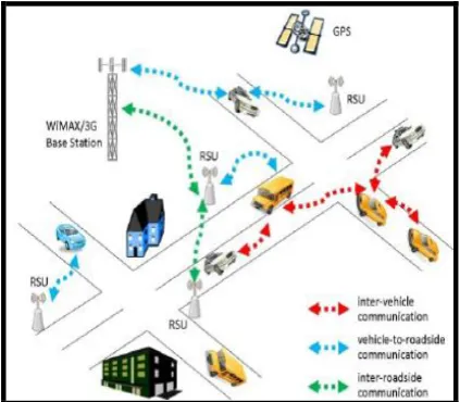
Vehicular Ad-hoc networks (VANETs) are defined as a subset of traditional Mobile Ad-hoc networks (MANETs). The main feature of VANETs is that mobile nodes are vehicles endowed with sophisticated ―on-board‖ equipments, travelling on constrained paths (i.e., roads and lanes), and communicating each other for message exchange via Vehicle-to-Vehicle (V2V) communication technology, as well as between vehicles and fixed road-side Access Points , in case of Vehicle-to-Infrastructure (V2I) communications[2].
Forgetting traditional vehicles, in the next few years we will drive smart —intelligent— vehicles, with a set of novel functionalities (e.g., data communications and sharing, positioning information, sensor devices, etc.)[3].
We consider a VANET in which N numbers of vehicles are separated by the safety distance (between consecutive vehicles). Proposed VANET is
purely based on vehicle-to-vehicle (V2V) architecture, where both the collection and the restitution of information are done within the VANET.. All vehicles are equipped with General Positioning Systems (GPS) and on-board communication devices for communication. Each vehicle is loaded with location digital map and is concerned about road information ahead of it on its direction. Each vehicle communicates with other vehicle within its communication range R. If the neighbour vehicle is not within communication range R, the vehicle delivers critical data to the data center ―D‖, which may be associated with traffic light at cross junction. Safety information in vehicle is determined by particular set of sensors.
Fig. 1 Example of VANET Network
The primary objectives of VANET is to provide road safety measures by exchange of information between Vehicles in form of data packets which consists of various parametric information, these parameter are called mobility parameter. The parameter of data are about Vehicle‘s Current speed , distance and position.
minimum distance between vehicles using ultrasonic sensors, speed of vehicles using infrared sensor with attached center shaft motor and For knowing position of vehicles in an network for VANET application such as collidance warning avoidance it is essential to find location coordinates of vehicles using a set of GPS ,vibration sensor and RF technology. Section IV circuit, design and hardware system model of network. We provide the scope for further work and conclude in section V.
II. RELATEDWORK
VANET implementation in a real time system is a challenging task. Many such implementations have been deployed in recent years and implementing such projects in a real time system requires complete simulation by measuring the performance of the system. Many car producing companies like BMW, Audi, Ford, General Motors, Daimler, Nissan and so on are using the ITS systems for passenger safety. The C2C-CC project started in 2001 which uses the IEEE802.11 WLAN in 100 m. This project is mainly designed for V2 V communication[4]. The Fleetnet (2000–2003) project uses GPS information for V2 V and V2Icommunication. It is mainly distribute in urban areas and simulated by the Fleetnet Demonstrator[6]. PreVent (2004–2008) project uses sensors, communication systems. CVIS (2006– 2010) is a project mainly developed for providing V2 V communication.. CarTalk (2000–2003) is a project used for Advance Driver Assistance (ADAS), Advance Cruise control and Collision Avoidance Systems[7]. The CARLINK project is used for generating intelligent wireless communication between vehicles[8]. SEISCINTOS is a project which mainly concentrates on providing intelligent communication in MANET, VANET and WSN.
SAFESPOT is a project which mainly focuses on safety communication between the vehicles. SEVECOM stands for Secure Vehicles Communication[9]. It is a European Union project to which provides security to the system. NOW (Network-on-Wheels) (2004-2008)[10]: A German government supported project, established by vehicle manufactories and academic centres. Its goal was performing optimum protocols for transferring messages in addition methods for secure data transfer that used in C2C communication consortium.
III. PROPOSED RESEARCH METHODOLOGY
In order to create ad-hoc environment the performance of the wireless network between vehicle can be impacted from variety of parameter for that an effective research methodology is required in VANETS. The on-board sensors are
A basic safety message (BSM) is exchanged between vehicles and contains vehicle dynamics information such as distance, speed, and location. The BSM is modified and broadcast up to 10 times per second to surrounding vehicles. The information is received by the other vehicles equipped with V2V.
Fig. 2 SHOWS TYPE OF MESSAGES TRANSFERRED BETWEEN NODES
A. Distance Parameter Calculation
Our system model considers three vehicles in the wireless vehicular network. For identifying the neighbours, distance is the major issue which has to be known by nodes. For distance ultrasonic sensor is equipped in each vehicle on all the four side of it. Each vehicle receives its neighbouring nodes distance within its wireless range then gives it to microcontroller based on that vehicle will only display the minimum safe distance closest to it in LCD DISPLAY.
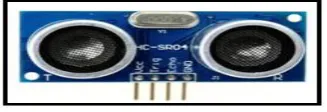
The system uses Ultrasonic ranging module HC - SR04 provides 2cm - 400cm non-contact measurement function, the ranging accuracy can reach to 3mm. The modules includes ultrasonic transmitters, receiver and control circuit. This particular sensor sends out an ultrasonic sound that has a frequency of about 40 kHz. The sensor has two main parts: a transducer that creates an ultrasonic sound and another that listens for its echo.
Fig. 3 HC-SR04 ULTRASONIC SENSOR
in the formula because the sound has to travel back and forth. First the sound travels away from the sensor, and then it bounces off of a surface and returns back .This ultrasonic sensor measures under non line of sight environment to calculate distance in vehicular environment.
B. Speed Parameter Calculation
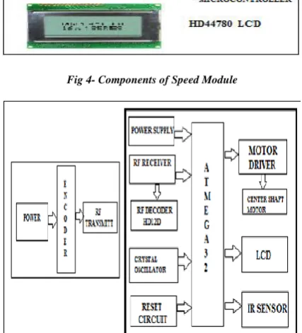
Another imported aspect for VANET approaching the vehicle is about the speed at which its neighbouring vehicles are coming to it. The RF transmitting circuit consist of a RF transmitter module interfaced with HT12G encoder and the user can select the ID using binary logic .The voltage regulator circuit is obtains power from a 8 volt(1 A) battery which provides the motor with unregulated 8 volt supply and whereas micro controller, motor driver, LCD and the receiver module receives a 5 volt regulated supply. The IR sensor is used to determine the speed of the DC motor, which sends the speed of the wheel to the microcontroller and displays it on the LCD display which is compared The controlling device of the whole system is a Microcontroller to which RF receiver module is interfaced with L293d is connected; DC motors are interfaced through a motor driver. The IR sensor is used to determine speed of the DC motor.
1) ATMEGA32 - It is a low power, high performance CMOS 8-bit microcontroller with 8K bytes of programmable Flash memory in built.
2) CENTER SHAFT MOTOR
100 RPM Center Shaft Economy Series DC Motor is high quality low cost DC geared motor .It has steel gears and to ensure longer life and better wear and tear properties. The gears are fixed on hardened steel spindles polished to a mirror finish. The output shaft rotates in a plastic bushing .The whole assembly is covered with plastic ring. Although motor gives 100 RPM at 12V but motor runs smoothly from 4Vto12V and gives wide range of RPM and torque.
3) INFRARED SENSOR- Infrared sensor is used with motor drive, to rotate the wheel of vehicle center shaft motor is used .As the wheel complete one rotation ,IR sensor attached to it will emits light from IR transmitter and IR receiver receives it. For one rotation speed is calculated as revolution per sec. This speed value is divides by 60 for revolution per min (RPM). Revolutions per minute, is measure of the frequency of a rotation. It annotates the number of turns completed in one minute around a fixed axis.
Fig 4- Components of Speed Module
Fig. 5 Transmitter And Receiver Module
4) HD44780 LCD
A single HD44780U can display up to one 8-character line or two 8-8-character lines. The HD44780U dot-matrix liquid crystal display controller and driver LSI displays alphanumeric, Japanese kana characters, and symbols.
C )Position Parameter Calculation:
In Vehicular Ad-hoc Network (VANET), localization is becoming a critical necessity since many VANET applications require position data ..The use of GPS unit within the vehicle allows knowing the vehicle position by finding its location coordinates
1) Calculation of vehicle’s safety zone coordinates
Figure-6 shows the calculation of the four safety coordinates of a vehicle. The front (F) and back (L)
Fig. 6 Schematic diagram for calculating the four safety-coordinate of a vehicle.
It is assumed that the GPS receiver is placed at the middle of the sideways safety clearance (W/2). The GPS coordinates are received at the point G (x, y). Let F = Front safety distance of the vehicle from G,
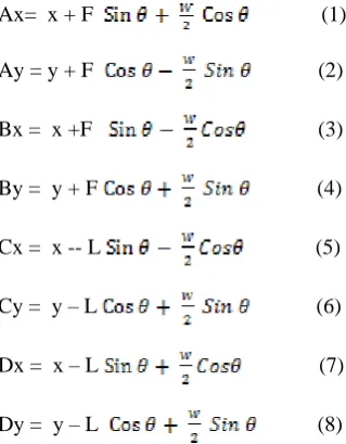
L = Back safety distance of the vehicle from G, W = Width of the safety clearance of the vehicle side wise, = Azimuth angle in degree. The four coordinates are then calculated as:
Ax= x + F (1)
Ay = y + F (2)
Bx = x +F (3)
By = y + F (4)
Cx = x -- L (5)
Cy = y – L (6)
Dx = x – L (7)
Dy = y – L (8)
The different dimensions are incorporated in the values of L and W. The speed and the braking power of a vehicle are included in different values for F.
2) Transmission of safety coordinates
We build a packet with the calculated coordinates and transmit on the 2.4 GHz ISM band using the 802.15.4 standard .The packet structure is as in Figure 8 . Each communication device is pre-burned with a 16 bit unique address that forms the short address (as defined in the standard) and represents a vehicle. The time field is obtained from the GPS
‗ddmmhhmmss’ corresponding to the date, month, hour, minutes and secondsand accounts for 10 bytes. The Latitude is made up of 9 bytesand is of the form yyyy.yyyy while the longitude is of the form xxxx.xxx and thus is transmitted as a 8 byte ASCII value.
Fig. 7 Packet structure with the coordinates of the safety zone. This packet is transmitted periodically by every vehicle.
Fig. 8 Modern vehicle with GPS and vibration sensor
VI . CIRCUIT, DESIGN AND HARDWARE SYSTEM MODEL OF NETWORK:
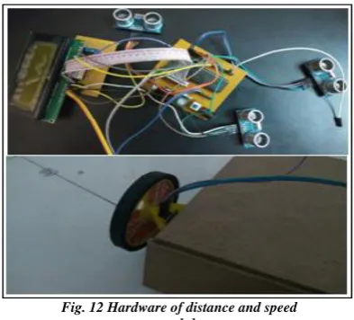
The hardware system consists of all three module of determining parameter is installed in the vehicle forming VANET network
Fig. 10 Architecture of the System
Fig. 11 LCD display output of all parameter
Fig. 12 Hardware of distance and speed module
V. CONCLUSIONS AND FURTURE WORK
In this paper we have developed a vehicular ad-hoc environment by proposing a network vehicle model using microcontroller, sensors and communication technology.V2 V exchange of status information take place ,where LCD embedded in all the vehicles shows speed, position, distance between each other. Also one application of VANET is performed that is accident detection/avoidance to shows the network connectivity of models ,to accurately characterize effect of vehicle mobility on VANETS.
Vehicular technology is gaining momentum as vehicles are increasing in a rapid manner.. The future of VANET is very bright as new ideas and scopes are coming up in recent times. Researchers are working in these upcoming areas to provide safety and security to mankind. Fig.13 shows the future research areas in VANET. The areas are briefly described as follows:
Fig. 13 Future research areas
Vehicular cloud: Implementation of cloud computing concepts can provide services in software, hardware and platform level. The main use of cloud computing is to provide on-demand resources to the users using virtualization. By using cloud, many applications are projected like multimedia services, data delivery, location sharing, e-applications, P2P services (Peer-to-Peer) and so on. The vehicles with internet access can form a network cloud to provide content delivery and information sharing. The storage can also be used as a service because cars have terabytes of memory. This technology therefore had a wide scope in future.
Fault tolerance: VANET is a network consisting of vehicles which act as nodes. The nodes can fail at any time because of hardware tampering or software fault and this leads to the generation of faulty nodes in the system. At the time of routing, if a vehicle sends data to a faulty vehicle then data may be dropped and delay increases. Hence, there should be a recovery ,method which recovers or protects the network from these faults. The generation of new fault tolerance techniques nowadays is also an emerging area of research.
Mobility model: To enhance the performance of the network there should be a realistic mobility model . A mobility model can be designed by considering vehicles, buildings, roads, maps, vehicular density, driver‘s behaviour and so on
ACKNOWLEDGMENT
REFERENCES
[1] Azzedine Boukerche , Horacio A.B.F. Oliveira an Eduardo F. Nakamura ― Vehicular Ad Hoc Networks‖:A New Challenge for Localization-Based Systems, FUCAPI- analysis research and technological innovation center brazil ,article on press Elsevier, 2008.
[2] VANET Vehicular Applications and Inter-Networking Technologies Ed. H. Harteinstein, K.P. Labertaux, John Wiley & Sons, Ltd., Mar. (2010).
[3] Moustafa, H, & Zhang, Y. Vehicular Networks: Techniques ,Standards ,and Applications, Auerbach Publications , Taylor and Francis Group, 450 pages, Ch. 2, (2009).
[4] Car-to-Car Communication Consortium, ―C2C-C Manifesto,‖ Version 1.0, July 2007 , available at http://www.car-to-car.org/ .leading / document/ pdf/ C2C-CC ,manifesto, v1.0 2007-05-17.pdf.
[5] Wenshuang Liang, Zhuorong Li and Rongfang Bie , ―Vehicular Ad Hoc Network: Architectures , Research Issues, Methodologies Challenges, and Trend‖, Hindawi Publishing Corporation International Journal of Distributed Sensor Network Vol 2,(6) Nov2015.
[6] Festag, A., Fubler, H., Hartenstein, H., Sarma, A., Schmitz, R. ‗FleetNet: bringing car-to-car communication into real world‘. Proc.11th World Congress on Intelligent Transportation Systems, Nagoya, Japan, October 2004 [7] Panos Papadimitratos, EPFL Arnaud de La Fortelle, Mines
ParisTech Knut Evenssen, Q-Free ASA Roberto Brignolo and Stefano Cosenza,‖ Vehicular Communication Systems :Enabling Technologies, Applications, and Future Outlook On Intelligent Transportation‖, IEEE Communications Magazine • November 2009
[8] Goh Chia Chieh and DINO ISA,‖ Low cost approach to real-time vehicle to vehicle communication using parallel CPU and GPU processing‖, (IJACSA) International Journal of Advanced Computer Science and Applications, Vol. 3, No. 12, 2012
[9] C. F. W. X. Yuliya Kopylova, "Accurate Accident Reconstruction in VANET," in Data and Applications Security and Privacy XXV , Springer Berlin Heidelberg, 2011, pp. 271-279.
[10] Rakhee G Doijad and .P. A Kamble, ‖Design of Prototype model for Vehicle to Vehicle Secure Formatted Communication‖, International Journal of Advanced Research in Computer and Communication Engineering Vol. 4, Issue 7, July 2015.
[[11] V. Kukshya, H. Krishnan, and C. Kellum. Design of a system solution for relative positioning of vehicles using vehicle-to-vehicle radio communications during GPS outages. In IEEE Vehicular Technology Conference - Fall, volume 2, pages 1313–1317, 2005
[12] Chen Chen, Lei Liu, Xiaobo Du, Qingqi Pei,1 and Xiangmo Zhao,‖ Improving Driving Safety Based on Safe Distance Design in Vehicular Sensor Networks‖, Hindawi Publishing Corporation International Journal of Distributed Sensor Networks Volume 2012
[13] R. Parker, S. Valaee, Vehicle localization in Vehicular Networks, in: Vehicular Technology Conference, 2006. VTC-2006 Fall. 2006 IEEE 64th, 2006, pp. 1–5.