© 2016 IJSRST | Volume 2 | Issue 1 | Print ISSN: 2395-6011 | Online ISSN: 2395-602X Themed Section: Engineering and Technology
PI Controller Based IDBB Power Driver with High PF and Low
THD for LED Lamps
Gullipalli Anupama, Chintada Ravi
Department of Electrical and Electronics Engineering, Aditya Institute of Technology and Management, Tekkali, Andhra Pradesh, India
ABSTRACT
An IDBB converter circuit, which can act as a high power factor, low output current ripple, and good efficiency driver for power LED lamps. The input stage is based on the integration of buck boost converter which performs power factor correction (PFC) from a universal ac source, using the PWM operation mode as a control loop. The integrated double buck-boost (IDBB) converter features one controlled switch and two inductors that supply a solid-state lamp from the mains, providing high power factor and good efficiency. In this project, the IDBB converter is analyzed with and without Control algorithm (PI controller), and a design methodology is proposed using Matlab. It is demonstrated that, with a careful design of the converter, the filter capacitances can be made small enough so that film capacitors may be used. The results obtained using PI controller and fuzzy logic controller for the same circuit are compared and are presented which validates high input power factor and superior control over the output voltage.
Keywords: IDBB Converter, PI Controller, ThermalHarmonic Distortion (THD), Power LED, High Power Factor (HPF)
I.
INTRODUCTION
WHITE POWER LEDs are becoming an attractive light source, owing to their high reliability, long life, high color rendering index, and small size. In addition, there are commercially available units that can reach light efficiencies as high as 100 mW. All these features make white LEDs a good option to override fluorescent and other discharge lamps in many applications, including street lighting, automotive lighting, decorative applications, and household appliances. However, power LEDs suffers from several drawbacks. First, due to their nearly constant-voltage behavior, they cannot be supplied from the dc or ac input voltage directly. Therefore, some kind of current-limiting device must be used, similarly to the ballast used to limit the current through a discharge lamp. On the other hand, the high efficiency of power LEDs is only maintained under strict operating conditions, which include low direct current and low junction temperature. All these mean that the development of power supplies that achieve correct driving of the LED-based lamp is an important topic of research.
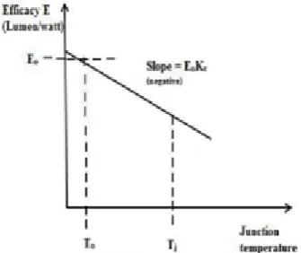
is 85%-90% of the input power into light energy, whereas the fluorescent lamps will produce only 77%. On the other hand global warming and increasing power demand etc. may be fulfilled by LEDs by implementing enhanced control technique (light dimming and preheating of filaments if possible). The recombination of electrons and holes can cause either photons (light) or phonons (heat). So the junction temperature of the LEDs increasing leads to the degradation of the luminous flux of LEDs .The high efficacy of power LEDs is only maintained under strict operating conditions, which include low direct current and low junction temperature (Fig 1).
All these mean that the development of power supplies that achieve correct driving of the LED-based lamp is an important topic of research. White power LEDs are becoming an attractive light source, owing to their high reliability, long life, high color rendering index, and small size. In addition, there are commercially available units that can reach light efficacies as high as 100 lm/W. All these features make white LEDs a good candidate to override fluorescent and other discharge lamps. The main drawback of these LEDs is they need constant voltage as input and they need current limiter before the input of the LED. Therefore, some kind of current-limiting device must be used, similarly to the ballast used to limit the current through a discharge lamp. On the other hand, the high efficacy of power LEDs is only maintained under strict operating conditions, which include low direct current and low junction temperature.
This drive is currently implemented with power electronic stages based on switch mode power supplies (SMPS). However, an electrolytic capacitor is required in these applications. Unfortunately, the operating life of such capacitors is by far shorter than the life of the HB LEDs, and usually are the shortest of all the devices in the power supply. Thus, removing the electrolytic capacitor would imply a remarkable increase in the operating life and reliability of the system. PFC converters can be classified into two types: two-stage and single-stage. Two-stage PFC converters consist of a PFC stage and a dc/dc stage. Single-stage PFC converters integrate the PFC stage and the dc/dc stage, leading to simple topology and low cost. They are suitable for low-power applications. The simplest active
PFC circuits are implemented with a single-stage that makes the power factor correction. The most common single-stage topology used is the fly back converter working in Discontinuous Conduction Mode (DCM), being called DCM fly back PFC converter. The main drawbacks of these pre-regulators are, by one hand, the high peak current stresses caused by the DCM and serious EMI problem and, by the other, the poor dynamics that these converters perform due to the low-pass filter (10 Hz-20 Hz) needed to reduce the input line current total harmonic distortion (THD). Therefore, if dimming operation is required, which must be done at frequencies above 200 Hz, these single stage solutions are not feasible. Attending to the reasons exposed above, a two-stage is needed so the Power Factor Correction can be done properly and a fast enough output dynamics is obtained. The numerous types of switching converter include boost, buck, buck-boost, and Cuk converters.
Figure 1. Efficiency versus Junction temperature of LED
II.
METHODS AND MATERIAL
A. IDBB Converter
current through the line will be proportional to the line voltage, therefore providing a near unity PF. On the other hand, the output inductance LO can be operated either in continuous conduction mode (CCM) or DCM. The operation in DCM has the advantage of providing a bus voltage across CB independent of the duty cycle and output power. However, it presents the disadvantage of requiring a higher value of the output capacitance to achieve low current ripple through the load.
Figure 2: Block Diagram of IDBB Converter
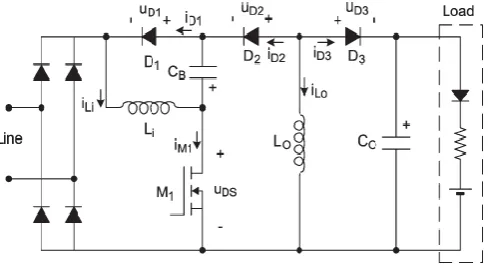
Figure 3: Schematic of IDBB Converter
B. Theoretical Analysis Offline IDBB Converter
In this section, the IDBB converter is analyzed when operated from the main voltage, achieving a near-unity input PF and a low-ripple current through the power-LED load. It is assumed that the line voltage is a sinusoidal waveform given as
vg(t) = Vg sin ωLt.
i. Line Current and Input Power
ii. Output and Bus Voltages
iii. Reactive Components
C. Power Factor Requirements For Offline LED Drivers
IEC (EU) requirements dictate THD performance for Lighting (over 25 W), other international standards apply depending on the region.
US DOE ENERGY STAR includes mandatory PFC for Solid State Lighting regardless of the power level. This is a voluntary standard and applies to a specific set of products such as down lights, under cabinet lights and desk lamps for example.
1) >0.7 for residential applications 2) >0.9 for commercial applications
While not absolutely mandated in the for lighting in all countries, it may be required based on the application:
Utilities drive major commercial uses to have high PF at the facility level
Moreover when utilities owns/service the streetlight it is in their interest to have good power factor, typically > 0.95+
III.
RESULT AND DISCUSSION
For the design of circuit component values, certain parameters are assumed approximately. Simulation results of IDBB converter using PI controller gives waveforms very close to standard waveforms. The input power factor of the converter can be viewed on the power factor display block. The control block as shown in figure generates the gate signal for controlling the switch.
subtracted from the reference current value to produce the error signal. This error signal is the input to the PI controller.
The controller output is so as to maintain the output current value close to reference value. The output of PI controller is fed to the saturation block. The saturation block is used to limit the controller output to a limited range; the range being decided by the upper and lower limits of ramp signal, a pulse is generated. In simulation the output values for ramp signal are chosen as 0 and 1. Therefore the saturation upper and lower limits are taken as 0.9 & 0.1 respectively. The ramp signal and controller output signal are compared in the relational operator block. Whenever the Controller output is greater than the ramp signal, a pulse is generated.
A. Algorithm For Input Voltage to the IDBB Converter
Step 1: start
Step 2: Enter the voltage values ranging from 190 to 250 V.
Step 3: Evaluate Source Voltage Vs=Vsi
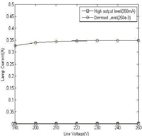
Step 4: Measured lamp current, PF, THD, Efficiency as a function of the input voltage at closed loop operation. Step 5: The above values (current, PF, THD, Efficiency) are noted for Buck Boost converter 1.
Step 6: The Same procedure is implemented for Buck Boost converter 2.
Step 7: Stop
Figure 4: Waveforms in MOSFET M1 at 230-Vrms line voltage.
Figure 5: Bus and output voltages at nominal power and 230-Vrms line voltage
Figure 6: Line voltage and current at nominal power and 230-Vrms line voltage.
B. Simulation OF IDBB Converter
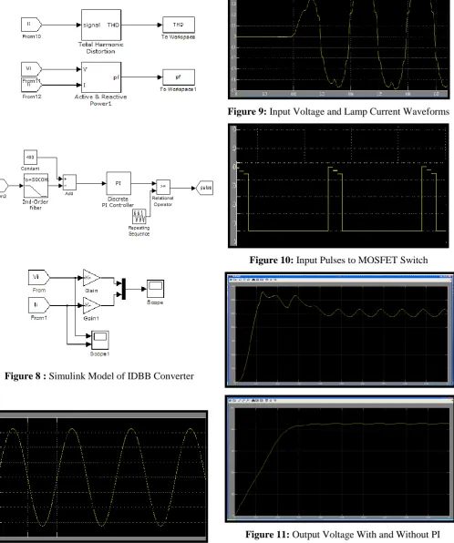
Figure 8 : Simulink Model of IDBB Converter
Figure 9: Input Voltage and Lamp Current Waveforms
Figure 10: Input Pulses to MOSFET Switch
Figure 11: Output Voltage With and Without PI
IV.
CONCLUSION & FUTURE SCOPE
An IDBB converter for power LED lamps was proposed which ensures high input power factor and low output ripple. The converter with PI control method was modeled in SIMULINK and waveforms were studied. The topology features two buck–boost converters in cascade but using only one controlled switch. By operating the input converter in DCM, a high input PF can be obtained. On the other hand, the operation of the second stage in CCM assures a low-ripple current through the LED load without using a very high output capacitance. In this way, the converter can be implemented using only film capacitors, avoiding the use of electrolytic capacitors and increasing the converter mean time between failures.
It can be used in led’s as the boost converter which boosts the energy and the led’s glow brightly. As now a days led’s are being used everywhere, this concept can be used for further better results. Even if any amount of rated voltage is given the buck boost converter can handle it and send the required voltage to led’s. It can be used even for the bunch of led’s for maximum efficiency. The overall efficiency can be increased by using Fuzzy controller. Galvanic isolation can be provided in the circuit using an inductor in the output circuit. Automatic dimming controls can be implemented for better efficiency when used for street lighting applications.
V.
REFERENCES
[1] E.F.Schubert, Light-Emitting Diodes, 2nd ed. Cambridge, U.K.: Cambridge Univ. Press, 2006. [2] Cree XLamp XP-C LEDs, 2010, Data Sheet No.
CLD-DS19 Rev 4.
[3] Y. Fang, S.-H. Wong, and L. Hok-Sun Ling, “A power converter with pulse-level-modulation control for driving high brightness LEDs,” in Proc. 24th Annu. IEEE APEC, Feb. 15–19, 2009, pp. 577–581.
[4] R. A. Pinto, M. R. Cosetin, M. F. da Silva, G. W. Denardin, J. Fraytag, A. Campos, and R. N. do Prado, “Compact emergency lamp using power LEDs,” in Proc. 35th Annu. IEEE IECON, Nov. 3–5, 2009, pp. 3494–3499.
[5] D. R. Nuttall, R. Shuttle worth and G. Routledge, “Design of a LED street lighting
system,” in Proc. 4th IET Conf. PEMD, Apr. 2–4, 2008, pp. 436–440.
[6] H. Yuequan and M. M. Jovanovic, “A novel LED driver with adaptive drive voltage,” in Proc. 23rd Annu.
[7] C. Qiao and K. M. Smedley, ―A topology survey of single-stage power factor correction with a boost type inputcurrent-shaper,in Proc. IEEE APEC 2000, pp.460–467.