DOI 10.1007/s12544-013-0092-2
ORIGINAL PAPER
Vehicle navigation system using UHF RF-ID
Vehicle navigation in an aspect of lane support system
Takeshi Kawamura·Tatsuya Kashiwa·Kenji Taguchi
Received: 28 March 2012 / Accepted: 29 January 2013 / Published online: 5 March 2013 © The Author(s) 2013. This article is published with open access at SpringerLink.com
Abstract
Purpose In northern countries, we sometimes encounter
heavy snow fall and it causes low visible condition. In this circumstance, we have difficulty to keep the driving lane. For the purpose of safety driving, we develop the vehicle navigation system with Ultra High Frequency (UHF) Radio Frequency Identification (RF-ID) to keep the driving lane.
Methods We obtain a vehicle location on the driving lane
using UHF RF-ID system. The vehicle position in driving lane is written on RF-ID tags in advance and these tags are buried in an asphalt road. Our experimental vehicle equips RF-ID antenna which communicates with RF-ID tags and gets vehicle location on the driving lane. This position infor-mation is given to a driver by Liquid Cristal Display. We make Graphical User Interface which shows vehicle loca-tion and direcloca-tion to the center of the driving lane. And our system gives voice instruction, which says the above di-rection. In order to simulate low visible condition, we put a bubble wrap on the windshield in front of driver’s seat. This bubble wrap makes driver difficult to see the outside. Results In our driving experiment with a daily driver and a novice driver, they can keep on the driving lane using our na-vigation system against the bubble wrap on the windshield.
Conclusions The navigation system with RF-ID is useful
under the low visible condition. And low visible condition is occurred in not only in the heavy snow fall, also thick fog and so on.
Electronic supplementary materialThe online version of this article (doi:10.1007/s12544-013-0092-2) contains supplementary material, which is available to authorized users.
T. Kawamura ()·T. Kashiwa·K. Taguchi Kitami Institute of Technology,
165 Koen-cho, Kitami, Hokkaido 090-8507, Japan e-mail: [email protected]
Keywords Vehicle navigation·UHF RF-ID·Graphical user interface·Voice instruction
1 Introduction
In the present paper, we investigate vehicle navigation using a Radio Frequency Identification (RF-ID) system. In the northern countries, we occasionally experiences heavy snow, which reduces visibility and causes traffic accidents. In order to prevent such accidents, we are developing a new navigation system that can indicate the vehicle location on the road.
Many vehicles are equipped with navigation systems that use the global positioning system (GPS). However, the accuracy of GPS is reduced for various reasons, and it cannot be used for precise vehicle navigation. Recently, a high-accuracy GPS system, named real-time kinemat-ics GPS (RTK-GPS), was developed. Although RTK-GPS can generally indicate the precise location of a vehicle, under certain conditions, for example, when reflected waves and waves arriving directly from GPS satellites are mixed, RTK-GPS sometimes provides incorrect location informa-tion. The system proposed in the present paper comprises a local communication system, which uses a communication method different from that of GPS.
estimation error, it is difficult to apply precise vehicle navigation, especially in low speed.
To our knowledge, there has been little experimental research on RF-ID systems. Reitaas et al. placed RF-ID tags on a straight road to ensure that a vehicle remained within its own lane [3]. Lee et al. studied the basic con-ditions of UHF RF-ID system on a straight road and have fruitful results in which RF-ID tags on road surface [4]. In each of these studies, RF-ID tags were placed on both sides of the driving lane and were used to provide out-of-lane warnings. RF-ID systems are also being developed for use in vehicle identification with Certified Weight in Motion (WIM) and video license plate recognition techniques [5]. Research has also been carried out on the use of passive RF-ID tag systems for indoor navigation of mobile robots [6]. Such robots move rather slowly compared to automobiles, and the distance between antennas and tags can therefore be much shorter.
During the winter, driving lanes are sometimes covered in heavy snow and the road and its surroundings become uniformly white. Headlights, fog lamps, and windshield wipers are not helpful and drivers struggle to identify the driving lane. A system that provides information on the location of the driving lane and helps the driver to remain in the center of the lane would be very useful under such conditions.
The prototype navigation system was designed to present driving information by means of an RF-ID system through a display on the dashboard. In our previous work [7,8], we use electromagnetic induction RF-ID (High Frequency 13.56 MHz). Using HF RF-ID system, we are also able to navigate the vehicle and keeping on a driving lane. By rea-son of HF RF-ID tags are placed on an experimental road surface, HF RF-ID tags were broken by heavy vehicles and snowplows. In order to improve the survival time of RF-ID tags, we attempt to set the RF-ID tags under a road sur-face and change the RF-ID system to Ultra High Fre-quency(UHF, 950 MHz). Lines of UHF RF-ID tags are set up under an experimental road surface on our campus. Since there has been no research on the communication range between an RF-ID antenna and buried RF-ID tags on an asphalt road, we first investigated the communication range of the RF-ID system on a dry asphalt road and an asphalt road covered with ice and snow during winter. We con-structed a prototype vehicle navigation system with a small Liquid Crystal Display (LCD) which indicates the position of the vehicle within the lane. In addition, the system is capable of issuing vocal instructions for remaining in the center of the lane. This is useful when driving on a straight road, even for novice drivers. These vocal instructions are issued by a computer which also displays the location of the vehicle on the road through a graphical user interface (GUI) using the Windows XP operating system.
2 Navigation system overview
The proposed navigation system is constructed using an OMRON V750 RF-ID system, which uses the UHF band (952–954 MHz) and is compliant with ISO/IEC 18000-6 Type C. The system incorporates an OMRON V750-BA50C04-JP reader/writer, an OMRON V750-HS01CA-JP circularly polarized wave antenna, and a laptop computer. In addition, we used Nitta Industrial G2-stick (φ 8 mm× 114 mm) RF-ID tags.
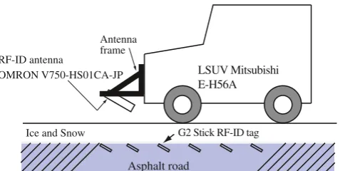
In the field experiment, a long-range antenna is placed on in front of a Pajero Mini E-H56A light sports utility vehi-cle (LSUV). The antenna frame is constructed of angle iron (Fig.1).
2.1 Buried angle of UHF RF-ID tags
When we prick a hole for stick type RF-ID tag, we usually dig vertically. But, stick type RF-ID tags talk back to a ver-tical direction of its axis. Stick type RF-ID tags on a wooden desk can communicate RF-ID antenna beyond 4 m long along RF-ID tag’s axis. But, same RF-ID tags on a concrete step only communicate 0.09 m long with RF-ID antenna on an extension of tag’s axis. Same phenomenon is occurred when we put stick type RF-ID tags into a vertical hole on an asphalt road. Stick RF-ID tags can communicate with RF-ID antenna whose height is under 0.09 m just above a RF-ID tag on the asphalt road. And we examine other 2 hole angle values for stick RF-ID tags, specifically 45◦and 30◦ to the road surface (Fig.2). As a result, Stick RF-ID tags of 45◦can communicate with antenna and its maximum height 0.27 m on an asphalt road. Stick RF-ID tags of 30◦ also communicate with antenna over 0.60 m long on the asphalt road. For our purpose, an antenna height is enough to the case of a stick RF-ID tag buried with 30◦ and we adopt a 30◦hole angle for stick RF-ID tags among three hole angles. Next, we investigate a communication range between stick RF-ID tag of 30◦angle and RF-ID antenna. We set RF-ID
Asphalt road Ice and Snow
LSUV Mitsubishi E-H56A RF-ID antenna OMRON V750-HS01CA-JP Antenna frame
G2 Stick RF-ID tag
UHF RF-ID tags Asphalt Road
Fig. 2 Side view of buried RF-ID tags with three hole angle, 90◦, 45◦, and 30◦
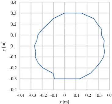
antenna parallel to the road surface and measure the com-munication range on the asphalt road (Fig.3). In this case, a RF-ID antenna is fixed on 0.40 m height on the asphalt road. And then we set the RF-ID antenna angle 30◦such that the antenna is parallel to RF-ID tag’s axis and measure the com-munication range on an asphalt road (Fig. 4). Improving the communication range and to be on earlier communica-tion between the RF-ID tag and the RF-ID antenna, RF-ID antenna is fixed with 30◦on the frame such that the RF-ID antenna surface parallel to the axis of stick RF-ID tag (Fig.1). We learn the maximum width of communication range of UHF RF-ID system is about 0.75 m. From this maximum value, we make RF-ID tags’ rows in experimental road. On each RF-ID tags’ row, we set RF-ID tags’ interval 0.80 m.
2.2 Experimental road
A schematic of the experimental road used for testing the proposed RF-ID navigation system is shown in Fig.5. We placed the RF-ID tags on the asphalt road. the width of the communication ellipsoid is approximately 0.75 m. The
-0.4 -0.3 -0.2 -0.1 0 0.1 0.2 0.3 0.4 0.4
0.3
0.2
0.1
0
-0.1
-0.2
-0.3
-0.4
x [m]
y
[m]
Fig. 3 communication range of RF-ID angled 30◦and RF-ID antenna parallel to the road surface, where RF-ID tag is buried obliquely downward along y-axis at (0, 0)
x [m]
0.8
0.7
0.6
0.4
0.2
0
y
[m]
-0.6 -0.4 -0.2 0 0.2 0.4 0.6
Fig. 4 communication range of RF-ID angled 30◦and RF-ID antenna angled 30◦, where RF-ID tag is buried obliquely downward along y-axis at (0,0)
maximum vehicle speed to maintain communication with this RF-ID system is given [9] as follows:
v= DT ×0.5 (1)
wherev is the maximum speed,Dis the moving distance in the communication envelope, T is the communication time (9 ms) in single read mode, and 0.5 is a safety margin.
On our experimental road maximum lengthD =0.7 m, then we have maximum speed with which we can read information on RF-ID tags is 140 km/h. This navigation system is designed for roads in urban areas, where the max-imum speed is restricted to 60 km. In winter, if the road sur-face is covered by ice and snow, driving at speeds in excess
1001 3001 5001 1003 3003 5003
2002 4002 6002 8002
1m 1m
0.8 m 0.8 m
0.8 m 0.8 m 0.8 m G2 stick RF-ID tag 2060 4060 6060 8060
0.8 m 0.8 m 0.8 m
4m
of 40 km/h is dangerous. In the case of reduced visibility, the driver should drive even more slowly. In view of these results, we set the interval between RF-ID tags to 0.80 m. If the maximum speed is 60 km/h, we have D =0.3 m, From Fig.4, the maximum width of communication range is almost 0.75 m. The proposed navigation system is devel-oped to allow safe driving during winter under low visibility conditions. Therefore, we investigate the effects of ice and snow on the communication range of the RF-ID tags dur-ing winter. The results are almost same as Fig.4, and it can be seen that a snow and ice cover causes only a very slight affect. Lane and location data is written into the RF-ID tags in advance, and these data can be rewritten. For a straight road, G2 stick RF-ID tags’ row on the experimental road is shown in Fig.5. The center of the odd rows, where the first digit of tags’ number is odd, is located along the center of the driving lane. There are sixty RF-ID tags’ rows in the driving lane.
3 Navigation system with UHF RF-ID
We designed a GUI for the proposed navigation system using the V750 developer’s kit. The GUI operates on Microsoft Windows XP and displays information read by the RF-ID antenna through the reader/writer.
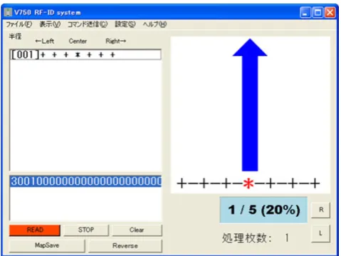
Tags’ information derived from the reader/writer is cal-culated on the laptop PC and shown driver through GUI on LCD. An example of GUI screen is given in Fig.6.
In this GUI, the upper left window shows the history of the read RF-ID tags. More precisely, [001], [002],. . .is the order in which the tags are read. For example, for the case in which this window displays “[004] + + + |*+ +”, “|” indicates the center of the RF-ID row, and “+” indicates
Fig. 6 GUI after reading some number of RF-ID tags
Fig. 7 GUI for the case of RF-ID antenna reading 3001 RF-ID tag on RF-ID tags’ row
other RF-ID tags’ position. In addition, “*” indicates the vehicle position in the RF-ID row. The lower window dis-plays numbers, which are written on the RF-ID tag and also show a short history. The arrow in the upper right window indicates the direction toward the center of the driving lane as well as the current location of the vehicle. This GUI is displayed on a 4-inch analog LCD that is connected to the laptop computer. This LCD is attached to the dashboard so that the driver can see the GUI. The experimental road is a commonly used roadway, and during the experiment there were pedestrians, bicycles, and other vehicles present. Under these circumstances, it was difficult to concentrate on the GUI alone during navigation. Therefore, in order to increase the safety of navigation, we incorporated a voice instruction system.
Fig. 9 GUI for the case of RF-ID antenna reading 1001 RF-ID tag
3.1 GUI design
Among RF-ID tags in same line, the center of driving lane is an ideal position and given a number as “3001” on the RF-ID tag. At this point, an antenna has a place within 0.375 m from the center of driving lane. When the antenna commu-nicates with this RF-ID tag, GUI shows a screen in Fig.7. Main display shows a vertical blue arrow. This blue arrow is adopted as safety image. It impresses drivers safety position on the lane. And the voice instruction says “Go straight”.
When the vehicle is to the right of the row and RF-ID antenna on 4002 RF-ID tag, the vehicle position remains safety position on the driving lane. And the antenna goes to 0.025–0.775 m from the center in the left direction. It is still safety and the direction to the center is a little bit right. Our GUI shows the screen with a right tilted green arrow (Fig.8). In this case, the voice instruction says “Right a little”.
Fig. 10 GUI for the case of RF-ID antenna reading 2002 RF-ID tag
Fig. 11 GUI for the case of RF-ID antenna reading 6002 RF-ID tag
At the second right ID tag from the center and RF-ID antenna reading 1001 RF-RF-ID tag (Fig. 9), the antenna is 0.425–1.175 m distant from the center of RF-ID tags’ row. In this case, drivers should be warned about veering out from the center of the lane. For this reason, we make a yellow askance arrow in the GUI screen. And the voice instruction says “Right turn”.
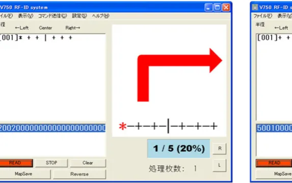
When the vehicle is at the left edge of the row of RF-ID tags and RF-ID antenna reads 2002 RF-ID tag (Fig.10), the antenna locates 0.825–1.575 m far from the center of RF-ID tags’ row. This antenna location is in danger of lane-out. An indication arrow in GUI screen becomes the red hook shape. And the voice instruction says “Right, right”.
Similar indication arrows and instructions are given when the vehicle goes to the right of RF-ID tags’ row. Following GUI screens are in the cases where RF-ID antenna reads 6002 (Fig. 11), 5001 (Fig. 12), and 8002 RF-ID tag (Fig.13), respectively. And the voice instruction
Fig. 13 GUI for the case of RF-ID antenna reading 8002 RF-ID tag
also says correspondingly ”Left a little”, “Left turn”, and “Left, left”.
4 Driving experiment on the road
We constructed an experimental road in our campus. We make driving experiment in Winter and test road is cov-ered with ice and snow. During the experiment, we put a 0.6 m×0.7 m bubble wrap on the windshield in front of driver’s seat to make the low visible condition caused by blizzard (Figs.14and15).
The test run is conducted when there are no pedestrians or other vehicles on the road. Because, avoiding an accident is most important issue in our experiment. Our experimental vehicle has no equipment for collision detection or pre-crash safety system, so we should keep off such accidents by our-selves. The driver looks only at the GUI on the LCD without looking outside, and receives voice instruction. Comparing
Fig. 14 Driver’s view without a bubble wrap
Fig. 15 Driver’s view with a bubble wrap on the windshield
with visible conditions, we make driving tests in the cases put on the bubble wrap on the windshield and without the bubble wrap. And in our experiment, there are two type of drivers, one is a daily driver, who drives almost every day, and another is a novice driver, who drives little or nothing, but has a driving license.
At first, we make a driving experiment without the bubble wrap. In this case, we can navigate an experimental vehi-cle by our navigate system. During driving experiments, we force the driver just look a LCD on the dashboard, in which our navigate GUI is shown, and never see the driving lane. Our navigation system is workable and we can keep the driving lane.
But, in this experimental condition, drivers can give a glance on the driving lane. After putting on the bubble wrap in front of driver’s seat on the windshield, drivers cannot see the driving lane surface and are able to see a vague out-line of oncoming vehicle and foot passengers. In order to assure the safety of driving experiment, we put the bubble wrap in front of driver’s seat and an assistant in front pas-senger seat checks the driving conditions and only gives a stop instruction to the driver in a dangerous situation.
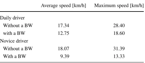
The low visible condition by the bubble wrap gives a psychological impact to the drivers. They cannot drive with bubble wrap on windshield without any navigation and guide. Drivers have learned our navigation system with RF-ID system, they know how vehicle position and direc-tion to the center of driving lane are indicated by our system. Reliability of navigation system is important point under the low visible condition. Both a daily driver and a novice driver decrease the driving speed (Table1). A novice driver is more affected by low visible condition, he decreases an average speed to 52 % and the maximum speed to 42.5 % from the driving experiment without the bubble wrap. And also a daily driver decreases an average speed to 73.5 % and the maximum speed to 65.5 % from the condition without the bubble wrap, respectively.
Table 1 Comparing the driving speed with/without a bubble wrap (BW) on the windshield
Average speed [km/h] Maximum speed [km/h] Daily driver
Without a BW 17.34 28.40
with a BW 12.75 18.60
Novice driver
Without a BW 18.07 31.39
With a BW 9.39 13.33
vehicle on the driving lane with the bubble warp on the windshield.
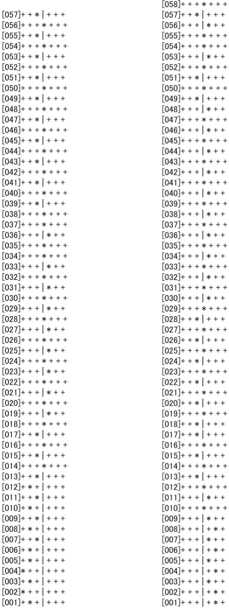
In the following, we show the representative driving records.
In the case of a daily driver, navigated vehicle starts from 3001 RF-ID tag and reads 55 RF-ID tags in Fig.17. In this case, an average speed is 11 km/h and the maximum speed is 15.54 km/h. On the other hand, a novice driver starts from 3001 RF-ID tag and reads 59 RF-ID tags. His average speed is 8.65 km/h and the maximum speed is 12.01 km/h. Both a daily driver and a novice driver can keep the driving lane and read in the midst of RF-ID tags. The movie taken in this driving experiment is given as Electronic Supplementary Material.
Next example is the case where experimental vehicle starts from right hand or left hand of RF-ID tags’ row. In this driving experiment, a daily driver starts from right hand of driving lane on purpose (Fig. 18). In this case, he can keep the driving lane and gradually drives to the center of driving lane. His average speed is 14.88 km/h and the max-imum speed is 22.61 km/h. A novice driver starts from left hand of the driving lane and he also keeps the driving lane by our navigation system. A novice driver drives the vehi-cle 9.18 km/h (average velocity) and the maximum velocity is 12.72 km/h. If drivers do not have sense of safety for our
Fig. 16 Experimental vehicle on the driving lane with the bubble wrap
Fig. 17 Driving record of a daily driver (left) and a novice driver
Fig. 18 Driving record of a daily driver (left) and a novice driver
(right). Start fromleft handorright handof the bottom line to the top
navigation system, they cannot drive vehicle over 10 km/h with bubble wrap on windshield.
5 Concluding remarks
In the present paper, we have presented a vehicle naviga-tion system that uses UHF RF-ID system to keep the driving lane. Our navigation system gives vehicle position on the driving lane by GUI on LCD and the direction to the center of driving lane by GUI on LCD and the voice instruction. In our residential area, heavy snow fall makes low visibility condition and we cannot drive around the legal speed. In our driving experiment, such low visible condition is simulated by the bubble wrap on the windshield in front of the driver’s seat. However, drivers feel the same difficulty of the heavy snow fall with wrapped windshield, our navigation system helps them to keep the driving lane safely. From several starting points on the driving lane, both a daily driver and a novice driver have done well with our navigation system using RF-ID system. In this paper, the low visible condition is assumed to be caused by the heavy snow fall, but same condition may be occurred in the dense fog and so on. Our navigation system with RF-ID system still has problems to put into practical use. Most important issue is cost in spread-ing RF-ID tags broadly on general road. From this point, we need to reduce the number of RF-ID tags. We might go on to more optimize the arrangement of RF-ID tags and work on multi-antenna system.
Acknowledgments The authors would like to thank students in our laboratory, who assisted in coding and conducting the experiments. The present study was supported by JSPS Grants-in-Aid for Scientific Research 18651082, 21510174, 23560433, and 24510221.
Open Access This article is distributed under the terms of the Creative Commons Attribution License which permits any use, distribution and reproduction in any medium, provided the original author(s) and source are credited.
References
1. National Highway Traffic Safety Administration (2011) Vehi-cle safety communications - applications VSC-A, second annual report
2. Alam N, Balaei AT, Dempster AG (2012) An instantaneous lane-level positioning using DSRC carrier frequency offset. IEEE Trans Intell Transp Syst 13(4):1566–1575
4. Lee EK, Yoo YM, Kim M, Gerla M (2009) Installation and evaluation of RFID readers on moving vehicles. In: Proceed-ings of the sixth ACM international workshop on VehiculAr Inter-NETworking (VANET’09), pp 99–108
5. Advanced Safety and Driver Support for Essential Road Transport (ASSET),http://www.project-asset.com/
6. Park S, Saegusa R, Hashimoto S (2007) Autonomous naviga-tion of a mobile robot based on passive RFID. Trans IEICE-A J90-A(12):901–909 (in Japanese)
7. Kawamura T, Yamamoto Y, Sugawara N, Kashiwa T (2009) Vehi-cle navigation system using RF-ID. In: Proceedings of the 16th ITS World Congress. Stockholm 2009, paper ID 3399
8. Kawamura T, Yamamoto T, Yamamoto Y, Sugawara N, Kashiwa T (2008) Experimental study for vehicle navigation system with RF-ID. In: Proceedings of the 2008 IEEE international conference on vehicular electronics and safety, pp 185–188