O R I G I N A L A R T I C L E
Open Access
Numerical and heat transfer analysis of
shell and tube heat exchanger with circular
and elliptical tubes
J. Bala Bhaskara Rao
1*and V. Ramachandra Raju
2Abstract
Background:Heat exchanger is a device in many industrial applications and energy conversion systems. Various heat exchangers are designed for different industrial processes and applications. Shell and tube heat exchanger (STHE) has its own importance in the process industries.
Methods:Experimental and numerical simulations are carried for a single shell and multiple pass heat exchangers with different tube geometries i.e. circular tubes to elliptical tubes. The experiment was carried out with hot fluid in tube side and cold fluid in shell side with circular tubes at 600 tube orientation and 25 % baffle cut. Heat transfer rates and pressure drops are calculated for various Reynolds numbers from 4000 to 20000. Fluent software is used for numerical investigations. Both circular and elliptical tube geometries with 450,600 and 900 orientations are used for the numerical studies. In addition to 25 % baffle cut, quarter baffle cut and mirror quarter baffle cut arrangements are used for comparison. The experimental values of heat transfer rates and pressure drops over shell side and tube side along the length of STHE are compared with those obtained from fluent software.
Results and Conclusion:It is found that the elliptical tube geometry with mirror quarter baffle cut at 450 tube orientation is 10 % higher than existing shell and tube heat exchanger and the pressure drop decrement in tube side shows up to 25 %.
Keywords:Shell and tube heat exchanger, Elliptical tubes, Heat transfer, Pressure drop
Background
Heat exchanger is a universal device in many indus-trial applications and energy conversion systems. Various heat exchangers are designed for different industrial processes and applications. In heat ex-changers, shell and tube heat exchanger presents great sustainability to meet requirements and gives efficient thermal performance. Shell and tube heat exchanger (STHE) is widely used in petro-chemical industry, power generation, energy conservation, and
manufacturing industry (Qian 2002). The baffle
member plays an important role in STHE, and it supports tube bundle and also equally distribute the fluid in the shell side. When segmental baffles are used in STHE which have many disadvantages (Kern 1950a; Li & Kottke 1998a), the low heat transfer is
achieved due to the flow stagnation, i.e., dead zones which are created at the corners between the baffle and the shell wall (Li & Kottke 1998b). It requires higher pumping power, and it creates a high pressure drop under the same heat load. The orientation of tubes will influence the annular surface area sur-rounded by the fluid. It is also influences the heat
transfer rate. The new baffle cut arrangement
achieved higher heat transfer rates and lower pres-sure drops (Master et al. 2006; Mukherjee 1992; Li & Kottke 1998c; Lei et al. 2008), so it is required to develop a new type STHE using different baffle cut arrangements to achieve a higher heat transfer rate. For the last few years, already described methods have been used to calculate heat transfer and pres-sure drop in the shell side of the STHE with dif-ferent baffles (Peng et al. 2007). The difdif-ferent calculation procedures have been checked against perimental measurements on a small-scale heat ex-changer. Kern method, Tinker method, and Delaware * Correspondence:[email protected]
1Department of Mechanical Engineering, SISTAM College, Kakinada, India Full list of author information is available at the end of the article
method (Palen & Taborek 1969; Kern 1950b; Tinker 1951) gave the best results in comparison to other methods in literature. The shell side design under the inside flow phenomenon must be understood by experimental and numerical analysis. The shell and tube heat exchanger design was explained by Gay et al. (Bell 1963) who worked on heat transfer, while Halle et al. (Gay et al. 1976) and Pekdemir et al. in-vestigated pressure drop (Halle et al. 1988; Pekdemir et al. 1994; Li & Kottke 1998d). Nowadays, the nu-merical methods have become an economical alter-native for the research of STHE, and through a detailed flow pattern and a temperature field, it could be obtained with much less difficult (Seemawute & Eiamsa-ard 2010; Rhodes & Carlucci 1983; Huang et al. 2001; Stevanovic et al. 2001). The collective effect of all the above parameters on heat transfer is quite in-teresting to design STHE with the optimistic ap-proach. Baffle cuts are placed to increase the flow rate in the shell side and also reduce the vibrations of the shell and tube heat exchanger. A STHE with 12 copper tubes and a stainless steel shell is used for the proposed system. Numerical analysis is con-ducted with elliptical tubes which are replaced by circular tubes. The modifications in the tube and shell overall pressure losses in the shell from the entrance to the exit points of the fluid are deter-mined. The pressure drops over the tube and shell sides are altered with tube orientations to give max-imum heat transfer efficiency. The baffle cuts are provided at 25 % with respect to the diameter and quarter baffle cut with respect to the cross sectional area. Mirror quarter baffle cut also is considered for effect-ive heat transfer. It is observed that heat transfer rate in-creases with the increase of the surface area.
Methods
Experimental setup
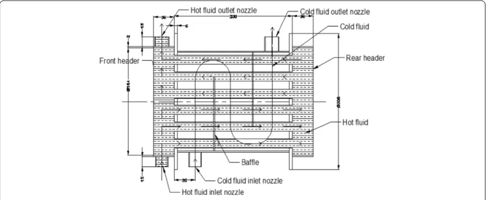
The shell and tube heat exchanger with circular tubes and 60° tube orientation for baffle using 25 % cut was taken as an experimental device. The dimensions of the STHE are shown in Fig. 1. The shell is made of stainless steel, and the tube is made of copper. The circulated hot fluid was used in the tubes and the cold fluid in the shell. The proposed model gives a flexibility to conduct several experiments; the scale of the model can be implemented for industrial applications.
The water is pumped from the water tank, and it is divided into two streams. One stream is a cold fluid which flows into the shell side of the STHE. The other stream is a hot fluid, which is heated by an electrical heater with a temperature control device, and it passes through the tube side of the STHE. The
flow rate is calculated by flow meters, and the flow was regulated by using valves. Thermocouples are used to measure the temperature of the inlet and out-let for the hot and cold fluids. The flow path of the hot and cold fluids and the attachments of thermom-eters, flow mthermom-eters, pumps, and valves are as shown in Fig. 2.
Shapes of tubes and baffles
Elliptical tubes with different orientations The copper tubes in the shell side are arranged with ellip-tical geometry. The ellipellip-tical tubes are prepared by equal volumes of elliptical and circular geometry. The ratio of the major axis to the minor axis of the elliptical tube is 2:1; 45°, 60°, and 90° orientation is maintained for the tubes as shown in Fig. 3a–c, respectively.
Different shape of the bafflesThe flow of the cold fluid is controlled by the shape of the baffle. The degree of tur-bulence created and energy utilized in the turtur-bulence are governed by the baffles. Different baffle cuts, i.e., 25 % baf-fle cut, quarter bafbaf-fle cut, and mirror quarter bafbaf-fle cut are used for this analysis. The baffles are not only meant for structural support but also increase the external surface area of the tubes which resulted in improvement in the heat transfer.
Numerical analysis and validation of the work
For the numerical analysis, the actual model is repre-sented as a virtual computer model using CATIA software package and analysis is performed with the help of a finite volume method as a computational fluid dynamics (CFD) tool. The inlet and outlet boundary conditions for the analysis are carried out as follows.
Geometric modeling and fluid properties for the analysis
for the different inlet mass flow rates as mentioned in the boundary conditions. Hence, the flow in the pipe as well as the shell is considered as turbulent. The max-imum temperature of the hot fluid is 348 K at atmos-pheric pressure, and it is in the liquid phase and water is an incompressible fluid; hence, Mach number is consid-ered in the incompressible region. The model is pre-pared as a three-dimensional geometric model for the analysis.
Inlet and outlet boundary conditions for the analysis of shell and tube heat exchanger
Inlet and outlet conditions for hot fluid The hot water is entered at a temperature of 348 K, and dif-ferent mass flow rates such as 0.15785, 0.3827,
0.55763, and 0.71782 kg/s are given at the inlet of the heat exchanger tube side nozzle. From the tube, the flow is considered to atmosphere pressure only. Based on the given inlet and outlet conditions, the inbuilt program of Fluent software calculated the remaining parameters.
Inlet and outlet conditions for cold fluid The cold fluid enters at a temperature of 298 K, and different mass flow rates such as 0.34589, 0.8403, 1.2245, and 1.5762 kg/s are given at the inlet of the heat exchanger shell side nozzle. The flow of the cold water is guided by the baffles provided over the tubes; the water is entered at 298 K and atmospheric pressure and it is exited from the shell outer nozzle into atmospheric pressure. Hence, the pressure boundary is defined at the outlet of the shell.
Other boundary conditions and grid generation No slip condition for the tube shell inner and outer surfaces is given. The tube shell and inlet outlet nozzles with uni-form cross sections are defined for the analysis. The dir-ection of the flow was defined normal to the boundary. Hydraulic diameter and turbulent intensity were speci-fied at the inlet nozzle of both hot and cold fluids. The flow is assumed as an incompressible turbulent flow; the gradient of temperature is required at all the points of the heat exchanger. Hence, the separate grid is generated for both tube and shell side fluids, and they are sepa-rated by the boundaries.
Grid generation
Due to the complicated structure of STHE, the com-putational zone was meshed with the structured and unstructured tetrahedral grid. The grid system is
Fig. 2Schematic diagram of the shell and tube heat exchanger
generated by ANSYS Workbench. During the verifica-tion of the grid system, the standard K-ε model is chosen. The Near wall region is meshed much finer (5.829e−002 mm) than shell wall regions in size to obtain optimized results as shown in Fig. 4a–c. For the high accuracy of numerical solutions, the grid in-dependent test was performed for the model. Three different grid densities (1,409,610; 1,319,030; and 1,221,673) are generated for the STHE (Reynolds number = 15,640 and mass flow rate = 0.55763 kg/s). It is found that the deviation between the results of the different grid systems was less than 3 %. The final grid system of 1,409,610 was adopted for the remaining computational models.
Numerical solution chosen for the analysis
The CFD solver FLUENT was employed to solve the governing equations. The SIMPLE algorithm was used to resolve the coupling between pressure and velocity field. The second-order upwind scheme was
Fig. 5Nodal points in the flow domain
Fig. 4aMeshed models for tubes and baffles at grid density 1,409,610.bMeshed model for tube side fluid at grid density 1,409,610.cMeshed model for shell side fluid at grid density 1,409,610
used for discretization pressure, momentum, energy, turbulent kinetic energy, and turbulent dissipation rates. The analysis is related to the fluid flow; there-fore, the finite volume method is chosen. There are three basic steps involved in the finite volume technique:
1. Integration of fluid governing differential equations over each control volume of computational domain. 2. Discretization of an integrated equation into an
algebraic equation/form which will be converted into a solution algorithm.
3. The control volume that will be solved in this discretized form equation will be used to write a solution algorithm for every iterative process until it satisfies the convergence criteria and stability.
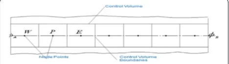
In finite volume method (FVM), the domain can be di-vided into number of control volumes and place number of nodal points between points as shown in Fig. 5.
In discretization of an integrated equation into an al-gebraic equation, the nodal point Pis is shown in Fig. 6.
The general equation for the fluid, when the fluid is incompressible, viscous, turbulent is
Z
cv
∂
∂tð Þρϕ dvþ
Z
cv
divðρϕuÞdv¼ Z
cv
divðΓgrad ϕÞdv
þ Z
cv
Sð Þϕ dv−1
whereφ= property of fluid ρ= density of fluid Γ= diffusion coefficient
S= source term
The general transport equation for a variable Ø in fi-nite volume method is
Rate of increase ofof fluid element
ð Þ
þ ðNet rate of fluid flow ofout of fluid elementÞ ¼ ðRate of increase ofdue to diffusionÞ
þ ðRate of increase ofdue to sourceÞ
where aw¼Γw
Aw
δxWP ;
aE¼Γe
Ae
δxPE
aP¼ðaWþaE−SPÞ
aP ϕP¼aW ϕWþaE ϕEþSu−2
The resulting system of the linear algebraic equa-tions is solved to obtain the distribution of the prop-erty Ø at the nodal point. The algebraic equations are solved by using direct methods (Cramer’s rule, matrix inversion, and Gauss elimination) and indirect or it-erative methods (Jacobi and Gauss-Seidel). The flow is incompressible turbulent; hence, the K-ε model is considered for the analysis. The K-ε model is the sim-plest turbulence model for which only initial bound-ary conditions need to be supplied and used for 3D
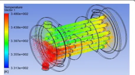
Fig. 9Tube side vector diagram of heat transfer
Fig. 7Virtual model of the heat exchanger
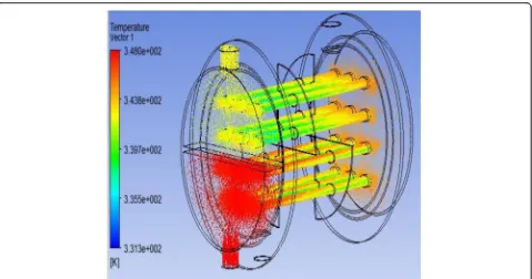
Fig. 8Shell side vector diagram of heat transfer
analysis in which the changes in the flow direction are always so slow that the turbulence can adjust it-self to local conditions. As per the grid density, the number of algebraic equations are generated for unite volume and the algebraic equations are solved numerically.
Validation of the analysis
The above boundary conditions, inlet and outlet conditions, and fluid properties are considered for the analysis, and the results are compared to the real model. The virtual model of shell and tube heat ex-changer is used for numerical analysis as shown in Fig. 7. Figures 8 and 9 show the variations of heat transfer in the shell side and the tube side of the shell and tube heat exchanger in vector form. The inlet temperature of the hot and cold fluids at different flow rates which are utilized to calculate the corresponding outlet temperatures using calcula-tion method is given in data appreciacalcula-tion. The heat transfer performance and pressure drop are evalu-ated, and these experiment values are tabulated in Table 1. The percentage of error is as shown in Fig. 10. The percentage of error is less than 8 %; hence, the considered boundary conditions are valid for the analysis of virtual model with modifications. Consequently, experimental results are closed to nu-merical results and the final concept is formulated towards CFD analysis for various configurations.
Data appreciation
The heat transfer rate and ultimately pressure drop were calculated from the initial data on the flow rates and the inlet and outlet temperatures of both shell and tube side of STHE. The heat transfer rate is obtained by the fol-lowing equation.
Q¼AUΔTm ð1Þ
where Q = average heat flux between the cold and hot fluid in watts
Q ¼ ðQCþQhÞ=2
QC¼mccpcðTco–TciÞ
Qh¼ mhcphðThi–ThoÞ
mc and mhare the cold and hot fluid mass flow rates in kg/s, respectively
cpcand cphare the specific heats under constant pres-sure of cold and hot fluids in kJ/kg K, respectively
A = surface area based on the tube outside diam-eter in m2
A ¼ ðΠDo LÞN
whereN= number of tubes
Do = outlet tube diameter in meters
L= effective length of the tube in meters
ΔTm= logarithm mean temperature difference for hot and cold fluid in kelvins
The heat exchanger is one shell and multiple tube
passesΔTm¼ t2−t1
ð Þð√1þR2Þ
ln½ð2−pð1þR−√1þR2Þ
2−pð1þRþ√1þR2Þ
ð
R¼T1−T2 t2−t1
P¼ t2−t1 T1−t1
where t1 and t2 are the shell side inlet and outlet temperatures, respectively, and T1and T2are the tube
side inlet and outlet temperatures in kelvins,
respectively.
From the above calculations, the overall heat transfer coefficient can be obtained by Eq. (1).
Heat transfer efficiency on the tube side can be ob-tained by
Fig. 10Comparison of the numerical analysis with the experimental results
Table 1Comparison of the numerical analysis with the experimental results
Reynolds number
Inlet temp (K) Heat transfer (watts) Percent
of error
Cold fluid Hot fluid Value by expt Value by numbers
4418 298 348 3419.85 3691.38 7.93
10,733 298 348 6799.85 7170.84 5.45
15,640 298 348 9018.42 9485.87 5.18
NU¼0:027 Re0:8Pr0:333
μf μw
0:14
For waterμf μw ¼1
The properties of water and flow parameters at 348 K for the tube side are used, and accordingly, Re and Pr
are calculated. The tube side film coefficient can be calculated by using
NU¼
hidi
k
whereNU= Nusselt number for the tube side di = inner diameter of the tube in meters
Fig. 12Stream lines of shell side heat transfer at mirror quarter baffle cut with circular tubes
K= thermal conductivity of hot fluid in W/m K The overall heat transfer coefficient for the shell and tube heat exchanger can be found by using
U¼ d0 1
dihiþ2dk01logddi0þho1
where hi and ho are heat transfer coefficients for
the tube side and the shell side in W/m2 K,
respectively.
k1= thermal conductivity of the copper tube in W/m K The shell side film coefficient (ho) can be obtained from the above equation.
Fig. 14Stream lines of shell side heat transfer at mirror quarter baffle cut with elliptical tubes
The pressure drop on the shell side of shell and tube heat exchanger is calculated by the equation
f ¼1Δp0
2ρu2
d0
l
wheref= friction factore(0.576−0.19 ln Re)
(FromHeat Exchangers: Selection, Rating and Thermal
Design, by Sadik Kakac and Hongtan Liu).
Results and discussion
The flow parameters are varied by introducing different tube geometries, different tube orientations, and differ-ent baffle cuts. Subsequdiffer-ently, more heat transfer rate is created in the flow by introducing more surface area, and a mathematical model is reformed for more numer-ical analysis. As per this type of analysis, observation is found that more heat transfer efficiency for dropping the pressures along the length of the shell and tube of the STHE.
Circular tube and elliptical tubes
Heat transfer analysis
Heat transfer with different baffle cuts In this experi-ment, three types of baffle cuts are used for the ana-lysis. The effects of heat transfer in the tube side and the shell side are investigated by using 25 % baf-fle cut, quarter bafbaf-fle cut, and mirror quarter bafbaf-fle cut. The cross section of the tubes which contain geometry such as circular, square, triangle, and elliptical will influence the thermal analysis due to variation of the surface area. Generally, a higher surface area gives higher heat transfer performance and vice versa. In the analysis, the circular tubes have a low surface area than the ellip-tical tubes. The vector contours in the mathemaellip-tical model shown in Figs. 11, 12, 13, and 14 for circular tubes without strip (CWOS) and elliptical tube without strip
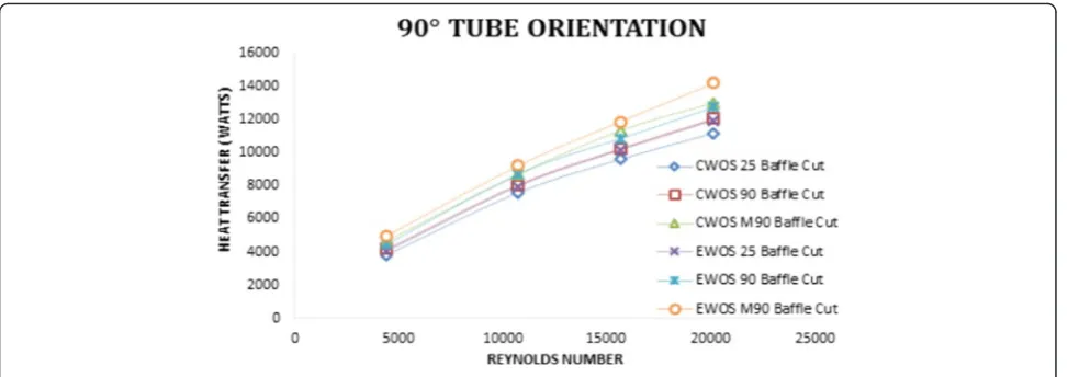
(EWOS) indicate heat transfer distribution in the tube side and the shell side of the shell and tube heat exchanger. Vi-sualizations are made on the elliptical model in compari-son to the circular model mathematical analysis. Temperature distribution for vector diagram indicates the heat transfer rate increase if tube geometry changes from circular to elliptical. The temperature of the hot water in the tubes at the inlet is higher than all other regions. In the case of the shell, the temperature of the cold water at the outlet is higher. From all graphs (Figs. 15, 16, 17, 18, 19, and 20), it shows that the heat transfer rate increases with an increase of Reynolds number. The baffle cut changes the direction of the flow of the cold fluid and the elliptical tube geometry increases the heat transfer rate due to the increase of the surface area. The heat transfer rate increases from 25 % baffle cut to quarter baffle cut and also quarter baffle cut to mirror quarter baffle cut.
In the case of the quarter baffle cut, the direction of the flow of the cold fluid changes in the X-Y
plane and also in the Z direction. As a result, the total length of the flow increased and the heat trans-fer rate also proportionately increased. In the circu-lar tube, the heat transfer rate increases up to 11 % when the 25 % baffle cut is replaced by quarter
Fig. 16Heat transfer at different baffle cuts with 60° tube orientation
baffle cut (90 baffle cut) and it is up to 10 % when the elliptical tubes are used from Figs. 15, 16, and 17. This is due to the increase flow length in the Z
direction. In the case of the mirror quarter baffle cut (M90 baffle cut), the flow of the cold fluid splits in two streams and follows the helical path due to the baffle shape. Separation of the cold fluid and in-crease in flow length leads to a better heat transfer rate. Figures 15, 16. and 17 indicate that the heat transfer rate increases up to 14 % when quarter baf-fle cut is replaced by mirror quarter bafbaf-fle cut in the circular tube, and it is up to 16 % if elliptical tubes are used.
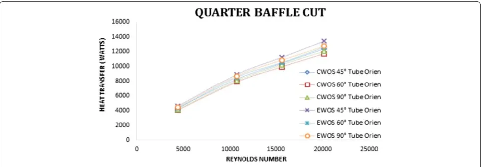
Heat transfer with different tube orientation The tube orientation influences the diagonal, vertical, and horizontal space between the tubes. At particular ar-rangement, the space is uniform and it may help for a better heat transfer rate. The temperature difference between the hot fluid and the cold fluid also
influences the heat transfer rate. Hence, for the tubes, different orientations 45°, 60°, and 90° are considered to find heat transfer variation along the tube side as well as the shell side. From all the graphs in Figs. 18, 19, and 20, values impose tube orientation from 60° to 90° heat transfer rate in-creases and the same against 90° to 45°. The heat transfer rate increases up to 6 % when the tube orientation changes from 60° to 90° in the circular tubes, and it is up to 8 % in the elliptical tubes. If the tube orientation changes from 90° to 45°, the heat transfer rate increases up to 6 % in the circular tubes and 9 % in the elliptical tubes.
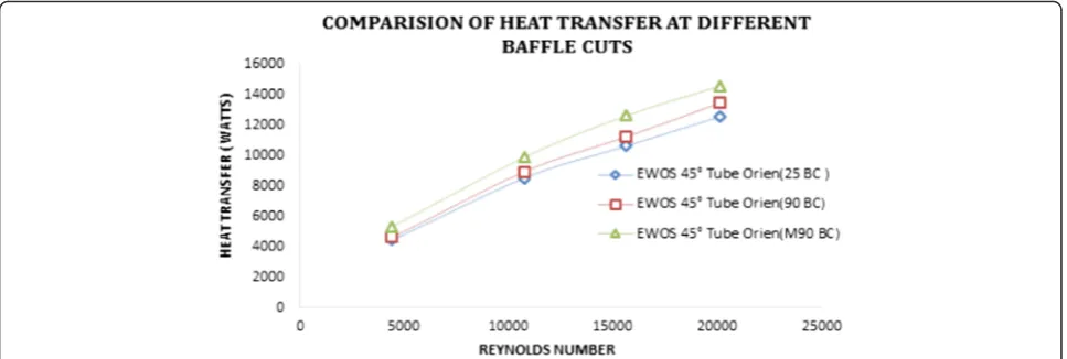
Comparison of heat transfer on the shell side and the tube side of the shell and tube heat exchanger If comparison is made between the circular tubes and the elliptical tubes, the heat transfer rate always increases in the elliptical tube geometry for all Reynolds numbers. Among all three baffle cuts, mirror quarter baffle cut gives
Fig. 18Heat transfer at different tube orientations with 25 % baffle cut
Fig. 21Comparison of heat transfer at different tube orientations with the maximum obtained baffle cut
Fig. 20Heat transfer at different tube orientations with mirror quarter baffle cut
better heat transfer rates as it shows in Figs. 21 and 22. As variation is made between the circular tubes and the elliptical tubes, the heat transfer rate in-creases up to 10 % for all three baffle cuts. While considering tube orientation, the elliptical tubes and different baffle cuts of 25 %, quarter and mirror quar-ter are maintained. Among all the tube orientations, 45° tube orientation gives the maximum heat transfer rate as it is shown in Fig. 21. Observations are found that the heat transfer rate increases up to 8–9.5 % of different orientations with the circular and elliptical tubes, respectively, and then the overall heat transfer improvement with mirror baffle cut 45° tube orienta-tion and elliptical tube is 10 % higher than the exist-ing shell and tube heat exchanger.
Pressure drop analysis on shell side
Fluid flow pressure, volume, and temperature are the three inter dependent parameters. The heat transfer is high when the temperature difference in hot and cold fluids is more and pressure drop is also high. But in the case of the heat exchanger, sudden high pressure drops are not to be encouraged. To avoid a high pressure drop in the heat exchanger, a uniform trans-fer of heat energy through the heat exchanger is re-quired. With this view, the pressure drop is calculated with different arrangements for the better perform-ance of the heat exchanger.
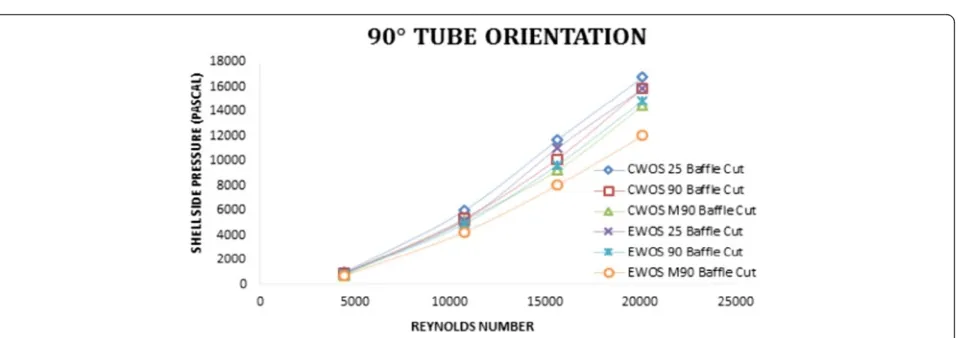
Pressure drop with different baffle cuts The baffle cuts influence the direction of the flow of the cold fluid, and the baffles give structural support to the tubes. The vector contours in the mathematical model shown in Figs. 23 and 24, for the circular tubes and the elliptical tubes, indicate pressure drop variation in the tube side of the shell and tube heat exchanger. The pressure drop increases with an in-crease of Reynolds number. The pressure drop de-creases from 25 % baffle cut to quarter baffle cut and also from quarter baffle cut to mirror quarter baffle cut. The total length of the flow increases in quarter baffle cut as compared to 25 % baffle cut, and it leads to a decrease of the pressure drop in the shell side of the shell and tube heat exchanger. The pressure drop reduced to 13 % for quarter baffle cut as compared to 25 % baffle cut in the circular tubes and to 15 % in the elliptical tubes as shown in Figs. 25, 26, and 27. In the case of the mirror baffle cut, the fluid in the shell splits into two streams, in-creases the flow path, and reduces the pressure drop in the shell side. The pressure drop reduced to 20 % from quarter baffle cut to mirror quarter baffle cut in the circular tubes and it is to 25 % in the ellip-tical tubes.
Pressure drop with different tube orientations The tube orientation for space distribution in the shell side influences pressure drop by different zones be-tween the tubes. Tube orientations are created by putting 45°, 60°, and 90°. Clearance space flow zone is more for 45°, 90°, and 60° and declined gradually. These flow zones gives less pressure drop as the free space creates less turbulence. Observations are made for the circular tube and the elliptical tubes at differ-ent oridiffer-entations such as from 60° to 90° and 90° to 45°. In the tube orientation for the circular tube at 60° to 90°, the pressure drop decreases to 30 % while the same at 90° to 45°, the pressure drop decreases by 20 % as shown in Figs. 28, 29, and 30. Similar for-mulations are made for the elliptical tubes at 60° to 90° tube orientation, the pressure drop decreases to 30 % while the same at 90° to 45° tube orientation, the pressure drop decreases by 25 % as shown in Figs. 28, 29, and 30.
Comparison of shell side pressure drop on the shell and tube heat exchanger If comparison is made in circular tubes and elliptical tubes, pressure drop de-creases in the elliptical tube geometry for all Reynolds numbers. Among all three baffle cuts, mirror quarter baffle cut gives lesser pressure drop as shown in Figs. 31 and 32. While considering tube orientation, the elliptical tube and different baffle cuts of 25 %, quarter, and mirror quarter are maintained. Among all tube orientations, 45° tube orientation gives mini-mum pressure drop as shown in Fig. 31. When obser-vations are found for elliptical tubes and circular tubes, then the pressure drop decreases to 20 % for different baffle cuts and it is to 18 % for different ori-entations. The overall pressure drop variation with mirror baffle cut 45° tube orientation and elliptical tube is 35 % lower than the existing shell and tube heat exchanger.
Pressure drop analysis on tube side
Fig. 24Velocity vector of tube side pressure drop at mirror quarter baffle cut with elliptical tubes
Fig. 23Stream lines of tube side pressure drop at mirror quarter baffle cut with circular tubes
Fig. 27Shell side pressure drop at different baffle cuts with 90° tube orientation
Fig. 26Shell side pressure drop at different baffle cuts with 60° tube orientation
Fig. 29Shell side pressure drop at different tube orientations with quarter baffle cut
Fig. 30Shell side pressure drop at different tube orientations with mirror quarter baffle cut
Fig. 31Comparison of shell side pressure drop at different tube orientations with the maximum obtained baffle cut
Fig. 32Comparison of shell side pressure drop at different baffle cuts with the maximum obtained tube orientation
Fig. 34Tube side pressure drop at different tube orientations with quarter baffle cut
Fig. 35Tube side pressure drop at different tube orientations with mirror quarter baffle cut
while the same at 90° to 45° tube orientation, the pressure drop decreases by 9 % as shown in Figs. 33, 34, and 35.
Comparison of tube side pressure drop on shell and tube heat exchanger In comparison made in the cir-cular tubes and the elliptical tubes, pressure drop decreases in the elliptical tube geometry for all Reynolds numbers. While considering tube orienta-tion of the elliptical tubes, different baffle cuts of 25 %, quarter, and mirror quarter are maintained. Among all tube orientations, 45° tube orientation gives minimum pressure drop as shown in Fig. 36. Observations are found for the circular tubes and the elliptical tubes, then the pressure drop decreases to 24 % for different orientations. The overall pres-sure drop variation with mirror baffle cut, 45° tube orientation, and elliptical tubes is 25 % higher than existing shell and tube heat exchanger.
Conclusions
In the present study, CFD analysis is conducted on cir-cular models and elliptical models of the STHE with various baffle cuts at different tube orientations. The tube geometry, tube orientation, and baffle cuts are con-sidered to enhance the heat transfer rate by minimizing the pressure drop. Based on the simulation results, the following conclusions are derived.
a. The overall heat transfer rate in the Reynolds number range between 4000 to 20,000 increases with mirror baffle cut, 45° tube orientation, and the elliptical tube geometry is 10 % higher than the existing shell and tube heat exchanger.
b. Pressure drop reduction in the shell side is more influenced by baffle cuts. The pressure drop is minimum in the case of 45° tube orientation and mirror quarter baffle cut with elliptical tubes due to a uniform heat transfer through the heat exchanger.
c. If the tube geometry changes from circular to elliptical, the pressure drop over the tube side will be decreased. The pressure drop decrement for the circular tube to the elliptical tube in tube with mirror baffle cut, 45° tube orientation shows up to be 25 %.
Funding
This research received no specific grant from any funding agency from the public, commercial, or not-for-profit sectors.
Competing interests
The authors declare that they have no competing interests.
Author details
1Department of Mechanical Engineering, SISTAM College, Kakinada, India. 2Department of Mechanical Engineering, JNTU Kakinada, Kakinada, India.
Received: 19 December 2015 Accepted: 4 May 2016
References
Bell, KJ. (1963) Final report of the cooperative research programme on shell and tube heat exchangers, University of Delaware, Engineering Experimental Station, Bulletin No. 5.
Gay, B, Mackely, NV, & Jenkins, JD. (1976). Shell-side heat transfer in baffled cylindrical shell-and-tube exchangers-an electro chemical mass transfer modelling technique.International Journal of Heat and Mass Transfer, 19, 995–1002.
Halle, H, Chenoweth, JM, & Wabsganss, MW. (1988). Shell side water flow pressure drop distribution measurements in and industrial sized test heat exchanger.Journal of Heat and Mass Transfer, 110, 60–67.
Huang, X, Lu, Z, & Wang. (2001). Numerical modelling of the shell side flow in the shell and tube heat exchanger. In W. Liu (Ed.),Proc. Int. Conf. on energy Conversion and application volume I, Wuhan, China(pp. 301–304). Kern, DQ. (1950a).Process heat transfer(pp. 127–171). New York: Mc-Graw-Hill. Kern, DQ. (1950b).Process heat transfer. New York: McGraw-Hill.
Lei, YG, He, YL, Pan, C., et al. (2008). Design and optimization of heat exchangers with helical baffles.Chemical Engineering Science, 63(17), 4386–4395. Li, HD, & Kottke, V. (1998a). Effect of leakage on pressure drop and global
heat transfer in shell and tube heat exchanger for staggered tube arrangement.International Journal of Heat and Mass Transfer, 41(2), 425–433.
Li, HD, & Kottke, V. (1998b). Visualization and determination of local heat transfer coefficient in shell and tube heat exchangers for staggered tube
arrangement by mass transfer measurements.Experimental Thermal and Fluid Science, 17(3), 210–216.
Li, H, & Kottke, V. (1998c). Effect of baffle spacing on pressure drop and local heat transfer in shell and tube heat exchangers for staggered tube arrangement.
International Journal of Heat and Mass Transfer, 41(10), 1303–1311.
Li, HD, & Kottke, V. (1998d). Visualization and determination of local heat transfer coefficient in shell and tube heat exchangers for staggered tube
arrangement by mass transfer measurements.Experimental Thermal and Fluid Science, 17, 210–216.
Master, BI, Chunangad, KS, Boxma, AJ, Kral, D, & Stehlik, P. (2006). Most frequently used heat exchangers from pioneering research to world wide applications.
Heat Transfer Engineering, 27(6), 4–11.
Mukherjee, R. (1992). Use double-segmental baffles in the shell-and-tube heat exchangers.Chemical Engineering Progress, 88, 47–52.
Palen, JW, & Taborek, J. (1969). Solutions of shell side flow pressure drop and heat transfer by stream analysis method.Chemical Engineering Progress Symposium Series, 65, 53–63.
Pekdemir, T, Davies, TW, Haseler, LE, & Diaper, AD. (1994). Pressure drop measurements on the shell side of a cylindrical shell and tube heat exchanger.Heat Transfer Engineering, 15, 42–56.
Peng, B, Wang, QW, Zhang, C., et al. (2007). And experimental study of shell and tube heat exchanger with continuous helical baffles.Journal of Heat Transfer, 129, 1425–1431.
Qian, SW. (2002).Handbook for heat exchanger design. Beijing: Chemical Industry Press (in Chinese).
Rhodes, DB, & Carlucci, LN. (1983). Predicted and measured velocity distributions in a model heat exchanger. InInt. Conf. on numerical methods in engineering Canadian nuclear society/American nuclear society(pp. 935–948).
Seemawute, P, & Eiamsa-ard, S. (2010). Thermo hydraulics of turbulent flow threw a round tube by a peripheral-cut twisted tape with an alternate axes.International Communications in Heat and Mass Transfer, 37, 652–659.
Stevanovic, Z, Ilic, G, Radojkovic, N, Vukic, M, Stefanovic, V, & Vuckovic, G. (2001). Design of shell and tube heat exchanger by using CFD technique—part one: thermo hydraulic calculations.Mechanical Engineering, 1(8), 1091–1105. Tinker, T. (1951).Shell side characteristics of shell and tube heat exchangers, parts I,