Autonomous Method for Object Based GUI
Testing using Image Processing
Sushma Suresh K
Aerospace Network Research Consortium, Indian Institute of Science (IISc), Bangalore, India
Abstract
One of the most important and crucial steps of the software development lifecycle is testing the graphical aspects of the application’s user interface. The major challenge here is to accurately detect and test the various visual elements of the application, in order to ensure its complete functionality. The proposed method uses image processing techniques to autonomously detect objects within the GUI application, based on the shape of the object. In the process of arriving at an optimized solution, a popular blob detection algorithm (MSER) has been studied and analyzed. One of the drawbacks of this method is its high levels of sensitivity thus resulting in its poor accuracy and making it unsuitable for such an application. Keeping this in mind, an alternate object
identification and localization technique has been put forward.
Comparisons done after thorough experimentation indicates this method to be more accurate in terms of detecting various objects present within the GUI application, thus aiding the testing process by making it completely autonomous and fail-proof.
Keywords
Computer Vision, MSER, Image Calibration, Histogram Equalization, Contour Detection, Centroid based Localisation
I. Introduction
The success of any GUI application is determined by knowing how well it interacts with the user through its interface. It includes how the user actions are performed in order to access various features in the application and whether or not the application responds in a desired and correct manner. This process of implementing a set of tasks on the GUI application in order to ensure its proper functionality is termed as GUI testing [11]. GUI testing can be performed both manually (by using a human tester) or automatically (with the help of a software program). Manual testing involves the presence of a human to validate all aspects of the system. It is an extremely tedious, time consuming task and can often be error
prone. Automating the process is an efficient, accurate, reliable and
a cost effective replacement to manual testing. This paper aims to
address one of the major challenges in this field, i.e. using images
to accurately perform autonomous detection and localization of the desired objects in a GUI application.
Currently, there are two main approaches to automated testing, namely Object Based Testing [4] and Image Based Testing [11].
Image based recognition uses predefined image templates of
the desired objects to detect them within an image of the GUI application. In object based recognition technique, commonly
found objects in a GUI image are identified and detected based on specific characteristics and features pertaining to the desired
objects. In Image based technique, slight graphical changes in the images would result in failure to locate the features of interest. In order to overcome such failures, object based feature detection using computer vision has been proposed.
In computer vision, one of the most popular and widely used algorithms for object based region and blob detection is Maximally Stable Extremal Regions (MSER). It is primarily based on the
idea where in there are no changes in the regions through a wide range of threshold values. It works on the principles of connected components, where the MSER is a stable number of covalent regions present in varied grey level sets of an image [7]. Since MSER is extremely sensitive, there is a possibility of detection of many undesired features. To overcome this drawback, shape based object detection has been proposed.
The proposed procedure for autonomous object detection and localization within an image of the GUI application is explained in detail in the below sections. The paper has been organized as follows. Section 1 contains introduction to Autonomous GUI Testing and implementing image processing for object detection and localization using Computer Vision. Section II focuses on the methodology adopted to accurately detect and locate the positions of objects/features. In Section III, the experimental setup and results have been discussed, compared and analyzed. And lastly in Section IV, we draw the conclusions.
II. Proposed Method
The following steps have been proposed for accurately detecting and localizing objects within the images of GUI
applications-Calibrate the camera
•
Capture images of GUI applications using calibrated camera
•
and pre-process the captured image Detect various contours within image
•
Perform relative localization
•
Step 1: Camera calibration is the process of finding the quantities
internal to the camera which further affects the imaging process. By calibrating the camera, the parameters of a lens or image
sensor can be estimated. The first set of parameters are intrinsic
(or camera dependant) and include the focal length, pixel size and coordinates of the centre of the image. The second set of parameters is extrinsic in nature (not camera dependant). Since the centre of the projection does not always coincide with the origin of the world coordinate system, the world coordinate system must be shifted into camera coordinate system using the vectors of rotation and translation, which form the extrinsic parameters [1]. The intrinsic camera matrix is represented as follows:
Where-fx and fy are the focal lengths in terms of pixel dimensions
•
cx and cy are the optical centers expressed in pixel
•
dimensions
Camera calibration is performed by capturing multiple images of the classical black-white chessboard as the input pattern in different positions. As the result of calibration, the camera matrix (containing the intrinsic as well as the extrinsic parameters) is
Step 2: Using the calibrated camera, images of the GUI application are captured. In order to ensure that the captured images match with the original golden image, feature matching techniques are
used. Feature matching is the process of finding corresponding
features from similar images (having a change in the view point) based on the distance. This involves having two images namely the source and the target. Descriptors of one feature in the source image are matched with all the other features in the target image using distance calculations. The pair having the least distance or
the closest feature is returned [3]. In order to find the key-points
and their respective descriptors, ORB matcher has been used for experimentation and analysis.
Unlike SIFT [15] and SURF [9], ORB is a non-patented technique which proves to be a good alternative in terms of computational cost and performance. ORB uses the FAST algorithm to locate
key-points and then applies Harris Corner measure to find the
top N points among them. A fusion of FAST algorithm and Brief descriptors has been done to enhance the performance. Many
modifications have been made to the FAST algorithm to make
it more robust and compute the orientation of the objects in the image. The intensity weighted centroid of each patch is computed with the located corner at the centre [10].The direction of the vector from this corner point to the centroid gives us the orientation. The best matches of points obtained using the ORB matcher are considered to develop the planar homography matrix which maps the points in the plane to the points in the image. The homographic matrix H is as
It can be observed that there are eight unique numbers in the homography matrix (namely h0 to h7). Hence a minimum of four non-collinear world points and their corresponding image points are required in order to estimate the matrix. More the number of feature matches, more accurate is the homographic matrix. By applying the homography to every point in the source image (by multiplying the obtained homography matrix with all the points), we can warp the image to make it appear in the same plane as the target image. Warping is the process of digitally manipulating an image such that the shapes and features within the image appear to be distorted [14]. In turn, they can also be used to correct any distortions, if found in the image.
Due to insufficient ambient lighting conditions, the captured
images may have lot of noise and distortions. In order to minimise/ remove the noise, the images are improved by converting them to a binary images and then applying the CLAHE algorithm [2]. CLAHE (Contrast Limited Adaptive Histogram Equalisation) is an adaptive method that redistributes the high intensity light values by dividing the image into many small regions and applying on each pixel, a transformation function derived from the corresponding region. This effectively improves contrast in the images (as compared to other adaptive techniques), at the same time, limiting
the amplification of noise that the non-adaptive equalisation can
give rise to. After equalising and normalising the image, edge detection with a suitable threshold is applied. Canny operator provides a good and reliable detection of the edges with a low error rate and thus canny edge detection has been applied to obtain clear and accurate edges [13].
Step 3: MSER algorithm for region detection is highly sensitive to noise and blur. Due to this reason, many small and undesired features in the image are detected [8]. To overcome this disadvantage of MSER, we propose shape based detection as an alternative method to accurately detect objects in the image.
Shape detection in computer vision is based on the principle of using the computer (or any autonomous system) to analyse and process the geometric shapes present in images [6]. Shape analysis
finds its application in various fields of image processing such as
remote sensing, medical imaging and GUI testing. In this method, the shapes of objects are detected based on our prior knowledge of their geometric properties and characteristics.
Since most objects or features within a GUI application (such as buttons, text boxes, icons etc.) can be characterised as basic shapes (such as square, rectangle, oval, hexagon etc.), this method of contour detection has been proposed. Thus, by accurately detecting the shapes within the image, we can effectively detect all the objects present in the image of the GUI application.
Proposed algorithm and
working-The pre-processed image is considered as input. 1.
The contours of all the objects within the image are found. 2.
As a result, we obtain a vector of points which lie on the edges of these objects.
The contours are then approximated by scaling it with 3.
accuracy proportional to the perimeter of the contour.
For each identified contour of object, the number of vertices
4.
can be determined by analysing the curvature made by each point in the boundary chain.
Consider P
5. 1(x1,y1), P2(x2,y2) to be the points on the ends of two vertices and P3(x3,y3) to be the point at the intersection of these two vertices.
The angle at the vertex is calculated as
The cosine values of all the obtained angles within each 6.
contour are computed and then sorted in ascending order of their values.
We then use the degrees obtained above and the number of 7.
vertices to determine the shape of the contour.
The detected shapes are highlighted and their centralised 8.
moments [4] given by Cx and Cy are computed
Where- M
• 00 is the area of the foreground region M
• 10 is the first order moment along x axis
M
• 01 is the first order moment along y axis
The count of these centroid gives us the number of identified
9.
objects.
that and obtain precise and optimum results, a number of filtering
techniques have been proposed. They are as
following-The maximum Region of Interest(ROI) in the image is 1.
identified at real time and all objects outside it are ignored.
To narrow down on the ROI, we limit the length of the contours 2.
detected to the number of vertices present in the shapes. Further, the minimum and maximum area of contours is set, 3.
which prevents the detection of very large and extremely small undesired objects.
To prevent multiple contour detection of the same objects, 4.
dilation of the Canny output image is performed which removes the potential holes between the edge segments after which binary thresholding at multiple levels is done. Thresholding has been applied based on the Euclidean 5.
distance between each of the moment centre points. This
helps in filtering out the presence of multiple moments for
the same detected objects.
Specifying the convexity of angles within the objects and 6.
approximating the polygonal contour curves with precision can further help in eliminating falsely detected shapes.
Step 4: Most existing object recognition systems decide only if the object is present within the image or not, but do not provide any information on the actual object location. Object localisation refers to determining or locating the exact positions of the detected objects within the image.
Once the all the desired objects have been detected and the centroid
points are obtained, we proceed to finding the location of these
objects in the real world. For this, each of the obtained centers is converted from their present pixel (image) coordinates to their respective homographic world coordinates with the help of the intrinsic camera parameters obtained during camera calibration. Mathematically, it can be represented as
follows- Where-(X
• n,Yn) are the homogeneous world coordinates for n th detected object
(x
• n, yn) are the obtained homogeneous pixel coordinates for nth detected object
(f
• x, fy) and (cx, cy) are the focal length and optical centre coordinates obtained from the intrinsic camera matrix As a result of this process, we obtain a list containing the world coordinates (at each centre) of all the detected objects within the image.
The results obtained during the various stages of proposed methodology have been analysed and discussed in the further sections.
III. Experimental Setup and Results
Based on the methodology adopted in Section II, the experiments are conducted for various sets of GUI application images as shown below. Fig. 1(a) is a number keypad of a door security system,
fig. 1(b) is an image of the start page in Windows 8 and fig. 1(c)
is a screenshot of the play store application on a smartphone. The considered images have different levels of complexity, in terms of the number of objects present in them for detection and localisation.
(a) (b)
(c)
Fig. 1: Various Input Images Considered
The images are taken using Logitech camera and processing has been done in python using the libraries of Open CV version-2.4.9. Both MSER based region detection and the proposed Shape based Contour detection algorithms have been applied on all the input images. The comparison between both the mentioned algorithms has been done to check for performance and accuracy in obtaining the centroid coordinates of desired objects.
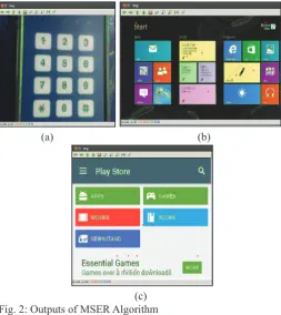
Pre-processing has been performed on the above shown input images and MSER algorithm for region based detection has
been applied. The results are as shown in fig. 2. The contours
are represented by green lines and the respective centroids by red dots.
(a) (b)
From the above results, it can be observed that MSER is extremely unstable and tends to detect many small regions as a separate component. Due to this reason, detection of many undesired
features can be noticed. In fig. 2(a) contours are detected outside
the ROI on either side. It can also be noticed that there is a problem
of overlapping blobs during detection. In fig. 2(b) every letter
in the GUI image is considered as a separate object leading to
redundant contour and centroid detection. In fig 2(c) MSER fails
to detect the boundaries of multiple objects in the image and a high number of false detections are observed. Since it is a self-iterative and incremental procedure, users cannot apply external
filters until the whole process is complete, in order to reduce
false detection.
To overcome the disadvantages of the MSER method, the Shape
based contour detection mechanism without filters has been
applied as an alternative. The results obtained after applying this algorithm to the pre-processed images is as shown in Fig 3. The red lines depict the contour boundaries and the corresponding centroid is represented by black dots.
(a) (b)
(c)
Fig. 3: Output of Shape Detection Algorithm Without Filters
Although the results of this method are comparatively (visually) better than that of MSER it has been noticed that the process of applying only basic shape based contour detection still results in quite a few number of false detections due to the presence of
unidentified (un-required) objects and noise in the image. In the case of fig. 3(b), within an object, multiple other objects have been detected. In fig. 3 (c), it can be noticed that some text present
within the objects have been detected as separate objects. This in turn leads more elements than desired being counted.
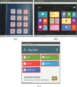
In order to further reduce the number of false detections, the
proposed filters are applied during shape detection. The results are as shown in fig. 4.
(a) (b)
(c)
Fig. 4: Results of Shape Detection Algorithm After Applying Proposed Filters
Fig. 4(a), (b) and (c), it can be clearly observed that regardless of the number and closeness of objects present in the image,
all the desired features have been identified with minimal false
detections.
The computed relative distance between the centroids of objects in the image can be checked against that found manually, to estimate correctness of the algorithm. Fig. 5 is a graph of the total number of objects detected during the application of each algorithm.
Fig. 5: Number of Objects Detected After Each Algorithm
From fig. 5 it can be observed that the number of objects detected
after using MSER is very high (due to false detections) as compared
to that after Shape detection. Applying the proposed filters further
Fig. 7: Error Rate of Applied Algorithms
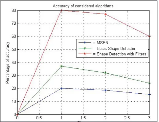
It is observed from fig. 6 and fig. 7 that the error rate increases with the number of objects to be identified in the image. MSER
has a very high error rate and very less accuracy. Basic shape based detector provides comparatively better results and after
applying the proposed filters, we obtain highly accurate results
with very low rate of errors.
IV. Conclusion
In this paper, the process of automated object based testing has been proposed for accurate detection and localisation of various features present in the image of a GUI application to perform
efficient GUI testing. Experiments have been conducted for
various sets of input images. The images are captured using a calibrated camera and pre-processed to correct its orientation and improve its contrast and lighting. Proposed shape based detection
algorithm is applied which identifies shapes in a GUI application
based on known characteristics and properties. The results are compared with those obtained using the existing MSER algorithm. Although the results are found to be much better, false detections still persist. To further reduce the false detections, this algorithm
is modified by adding filtering mechanisms. Experiments show
accurate results, thus making this system reliable and dependable for detecting desired objects and further localising them. The centroid coordinates obtained as a result of this method can be used by a robot, computer or any autonomous system for performing real time object localisation accurately.
References
[1] Y.M Wang, Y. Li, J.B. Zheng,“A Camera Calibration technique based on Open CV”, Information Sciences and Interaction Sciences (ICIS), IEEE, 2010.
[2] Rajesh Garg, Bhawna Mittal, Sheetal Garg,“Histogram Equalization Techniques For Image Enhancement”, IJECT Vol. 2, Issue 1, 2011.
[3] Richard Szeliski,“Feature Detection and Matching”, In Computer Vision: Algorithms and Applications, Springer, pp. 205, 2010.
[4] Dr. T C Manjunath,“Detection of Shapes of Objects Using Sophisticated Image Processing Techniques”, International Journal of Computer Science and Emerging Technologies, pp 32-37, Vol. 1, Issue 4, 2010.
[5] Rafael C. Gonzales, Richard E Woods,“Object Recognition”, In Digital Image Processing, Third Edition, Pearson, pp.
883.
[6] Mohd Firdaus Zakaria, Hoo Seng Choon, Shahrel Azmin Suandi,“Object Shape Recognition in Image for Machine Vision Application”, International Journal of Computer Theory and Engineering, Vol. 4, pp. 76-80, 2012.
[7] Hayko Riemenschneider,“Online object Recognition using MSER Tracking”, Masters Thesis, Institute for Computer Graphics and Vision, 2008.
[8] Ron Kimmel et.al,“Are MSER Features Really Interesting”, IEEE Transactions on Pattern Analysis and Machine Intelligence, Vol. 33, pp. 1-5, 2011
[9] Herbert Bay, Andreas Ess, Luc Van Gool et.al,“Speeded Up Robust Features(SURF)”, Computer Vision and Image Understanding, Vol. 110, Issue 3, pp. 346-259, 2008. [10] Ethan Rublee, Vincent Rabaud, Gary Bradski,“ORB:
An efficient alternative to SIFT or SURF”, International
Conference on Computer Vision (ICCV), 2012.
[11] Tom Yeh, Tsung-Hsiang Chang, Robert C Miller,“Sikuli: using GUI screenshots for search and automation”, Proceedings of 22nd Annual ACM Symposium on User Interface Software and Technology, pp. 183-192, 2009.
[12] Christoph H Lampert, Thomas Hofmann, Matthew B Blaschko,“Beyond sliding windows: Object localization by
efficient subwindow search”, Computer Vision and Pattern Recognition, IEEE Conference, 2008.
[13] Lijun Ding, Ardeshir Goshtasby,“On the Canny Edge Detector”, Pattern Recognition, Vol. 34, Issue 3, pp. 721-725, 2001.
[14] C A Glasbey, K V Mardia,“A review of Image Warping Methods”, Journal of Applied Statistics, Vol. 25, No. 2, pp. 155-171, 1998.
[15] David G Lowe,“Distinctive Image Features from Scale-Invariant Keypoints”, International Journal of Computer Vision, Vol. 60, Issue 2, pp. 91-110, 2004.
Sushma Suresh has received her bachelor’s degree in the field of Computer Science from Nitte Meenakshi Institute of Technology, Bangalore in 2016. She has worked as a Research Assistant as a part of the Aeronautical Network Research Consortium at Indian Institute of Science, Bangalore for a period of 7 months. Currently she is working as a Decision Scientist at Mu
Sigma, a leading data analytics firm at
Bangalore. Her research interests include Image Processing, Video Analytics and Machine Learning.