e-ISSN: 2278-7461, p-ISSN: 2319-6491
Volume 8, Issue 4 [April 2019] PP: 43-49
A Matlab/Simulink Design of an Orthogonal Frequency Division
Multiplexing System Model
Jeremiah Oluwatosin Bandele
Department of Electrical, Electronics and Computer Engineering, College of Engineering, Afe Babalola University, Ado-Ekiti, Ekiti State, Nigeria, P.M.B 5454
Corresponding Author: Jeremiah Oluwatosin Bandele
ABSTRACT:The design of an orthogonal frequency division multiplexing system model is shown in this paper using the discrete multitone modulation and in-phase/quadrature modulation technique. The Matlab/Simulink software is used for the design and while the complete system models were presented, a detailed description and explanation of each block in the model is shown. Results obtained show models where no errors bits were detected.
KEYWORDS: orthogonal frequency division multiplexing, discrete multitone, in-phase/quadrature.
--- --- Date of Submission: 01-01-2020 Date of acceptance: 16-01-2020 ---
---I.
INTRODUCTION
The Orthogonal Frequency Division Multiplexing (OFDM) scheme has been proved to be an effective solution to frequency selective channel response in an indoor wireless network (i.e. a multipath environment). In
single carrier modulation, a single carrier having a symbol rate R (i.e. symbol period, Ts = 1
R) symbols per second is used in the transmission of data serially over the channel. In a multipath fading channel, this leads to inter symbol interference (ISI) because the symbol period can be significantly less than the time dispersion thus requiring a complex equaliser to compensate for the channel distortion. OFDM offers high data rates, high bandwidth efficiency, immunity to ISI introduced by a multipath channel and avoidance of complex equalisers [1, 2]. A block diagram showing a communication system based on the OFDM modulation is shown in figure 1 below;
Figure 1: A block diagram showing a communication system based on the OFDM modulation [3]
In an OFDM transmission, multiple carriers N are used to transmit data symbols in a parallel manner by equally sharing the available bandwidth W. Each subcarrier is modulated at a lower symbol rate ∆f =W
operation is performed on the subcarriers resulting in a group of overlapping sinc functions. The frequency spectrum of OFDM subcarrier signals is shown in figure 2 below;
Figure 2: OFDM subcarrier signals (frequency spectrum) [4]
As observed in figure 2.3 above, though this signals overlap significantly, their orthogonal state remains the same because at the sampling instant of one of the subcarriers, the other subcarriers are zero [5, 6].In practical systems, a guard slot is added to the OFDM symbol to prevent channel distortions from disrupting the orthogonality of the subchannels. By adding a guard slot -which is shorter than the channel multi-path time spreading and longer than the symbol duration- to the OFDM symbol, it is possible to avoid inter symbol interference because the symbol period Ts of each subcarrier is longer than the channel multi-path time spreading (i.e. Ts ≫ τmax where Ts =
N
R and τmax= maximum delay). In radio frequency (RF) transmissions, a major disadvantage of an OFDM transmission is that the peak to average ratio (PAR) is quite high. Nevertheless, the high PAR (i.e. the time signal experiencing high variations) in OFDM can be used for intensity modulation of the optical source in visible light communication systems as the human eyes cannot observe these variations [2, 5, 7].
II.
THE OFDM SYSTEM MODEL DESIGN
The OFDM system model design is presented in this section of the report. The design format is related to the model in figure 2.2. The Matlab/Simulink software was used in modelling the system.
2.1 Discrete Multitone (DMT) Modulation Technique Design
In contrast to the conventional In-phase/Quadrature (I/Q) modulation OFDM technique that makes use of RF signals, the DMT modulation techniques does not require modulation with a carrier frequency. The DMT modulation technique applies Hermitian Symmetry in its operation. The Hermitian Symmetry permits the transmission of just the real part of the OFDM signal by setting the lower half subcarriers to the complex conjugate of the upper half conjugate. The transmitted real component of the OFDM signal is directly IM modulated over the optical carrier and connected to the decoder’s real input after photo-detection takes place [1]. A DMT current signal x(t) can be described as [8];
x t = XDC + Re M −1m =1sme−jwmt (1) where XDC= LED bias current, M= Number of subcarriers, sm= Transmitted QAM symbol in the mth subcarrier channel [8],
wm = 2πfm (2) and [8];
fm = m T (3) where T= Duration of the DMT symbol [8].
Figure 3: A DMT OFDM system model
Figure 3 above shows a DMT system model designed with the Matlab/Simulink software. A detailed description and explanation of some of the blocks used in figure 3 is given in figure 4 below;
(a)
(b)
(d)
(e)
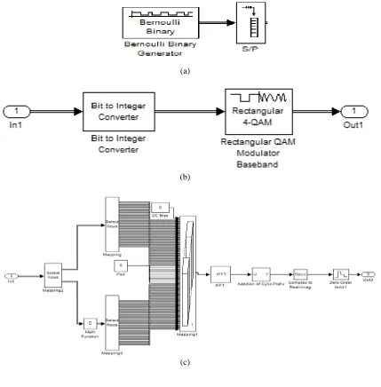
Figure 4: (a) Signal Generation and serial to parallel (S/P) conversion (b) Symbol Modulation in the QAM Modulation block in figure 4.1 (c) DMT Symbol Mapping, Inverse Fast Fourier Transform (IFFT)
Operation and the addition of Cyclic Prefix in the OFDM Modulation block in figure 3(d) Digital to Analogue (D/A) Conversion (e) Signal detection and error rate calculation
The serial binary data representing the transmitted signal is generated by the binary generator block shown in figure 4(a) above. The generated serial data is then transferred to a serial-to-parallel (S/P) converter. Since the OFDM modulation format basically involves parallel transmissions, the S/P converter converts the data into the required parallel. In Figure 4(b), the parallel binary data is then converted into integers which represent the symbols to be modulated. Modulation of the symbol takes place in the modulator block (i.e. in the model shown above, the 4-Quadrature Amplitude Modulation (4-QAM) format is utilized). DMT Symbol Mapping, Inverse Fast Fourier Transform (IFFT) Operation and the addition of Cyclic Prefix is shown in figure 4(c). The modulated symbols are mapped into the DMT format which involves executing the Hermitian Symmetry. The IFFT operation which is the major significance of the DMT OFDM modulation format is then carried out before the addition of cyclic prefix [1, 9]. The cyclic prefix addition helps to avoid intersymbol interference provided the multipath channel length is less or at most equal to the cyclic prefix length [2]. Figure 4(d) shows the digital to analogue converter (DAC) operation after a parallel-to-serial (P/S) converter converts the parallel data into a serial format. The received signal is detected and an error rate calculation takes place at the receiver section where a reverse operation takes place. As shown in figure 4(e), there was no error in the model because a no-noise/channel scenario was assumed in order to ascertain the basic working of the model.
2.2 In-phase/Quadrature (I/Q) Modulation OFDM Technique Design
This technique is similar to the DMT technique except that for the In-phase/Quadrature (I/Q) modulation and demodulation technique, Hermitian symmetry is not required and a carrier signal is required since information is transmitted over an analogue channel. The transmitted signal is modulated by the carrier signal frequency; producing real values from the complex transmitted OFDM signal. At the receiver, a reverse operation takes place; producing a complex version of the received photo-detected signal. A complex baseband signal xt t is separated into xI t and xQ t where xI t represents the baseband signal’s In-phase component and xQ t represents the baseband signal Quadrature component. PI(t)andPQ(t) refers to the cosine and sine carrier waves used to modulate and demodulate the I/Q components of the baseband signal respectively. Now [3];
PI t = 2cos(2πfct) (4) and[3];
PQ t = − 2sin(2πfct)(5)
wherefc represents the carrier frequency [3].
2.2.1 Modulation
sI(t) = xI t . PI t = xI t . 2cos(2πfct(7)
and the Quadrature baseband signal by the respective carrier wave is represented by sQ;
sQ(t) = xQ t . PQ t = −xQ t . 2sin(2πfct)(8)
By adding sI(t)and sQ(t), a real Signal, st(t) is produced;
st 𝑡 = 𝑠𝐼 𝑡 + 𝑠𝑄 𝑡 (9)
𝑠𝑡 𝑡 = 𝑥𝐼 𝑡 . 2 𝑐𝑜𝑠 2𝜋𝑓𝑐𝑡 −𝑥𝑄 𝑡 . 2𝑠𝑖𝑛(2𝜋𝑓𝑐𝑡) (10)
The signal 𝑠𝑡 𝑡 is the electrical current that drives the LED to produce light which is detected by the PD at the receiver after which demodulation occurs.
2.2.2 Demodulation
The transmitted signal, 𝑠𝑡 𝑡 received by the PD has to be demodulated into a baseband signal 𝑦𝑟 𝑡 . For In-phase demodulation, 𝑠𝑡 𝑡 is multiplied by the carrier wave 𝑃𝐼 𝑡 to produce the In-phase component, 𝑦𝐼 𝑡 as follows [3];
𝑦𝐼 𝑡 = 𝑠𝑡 𝑡 . 2 𝑐𝑜𝑠 2𝜋𝑓𝑐𝑡 (11)
𝑦𝐼 𝑡 = (𝑥𝐼 𝑡 . 2 𝑐𝑜𝑠 2𝜋𝑓𝑐𝑡 −𝑥𝑄 𝑡 . 2𝑠𝑖𝑛(2𝜋𝑓𝑐𝑡)). 2 𝑐𝑜𝑠 2𝜋𝑓𝑐𝑡 (12)
𝑦𝐼 𝑡 = 𝑥𝐼 𝑡 + 𝑥𝐼 𝑡 . 𝑐𝑜𝑠 2𝜋(2𝑓𝑐)𝑡 −𝑥𝑄 𝑡 . 𝑠𝑖𝑛 2𝜋(2𝑓𝑐)𝑡 (13) And after low pass filtering [3];
𝑦𝐼 𝑡 = 𝐿𝑃𝐹[𝑦𝐼 𝑡 ] (14)
For Quadrature demodulation, 𝑠𝑡 𝑡 is multiplied by the carrier wave 𝑃2 𝑡 to produce the Quadrature component, 𝑦𝑄 𝑡 as follows [3];
𝑦𝑄 𝑡 = −st t . 2 sin 2πfct (15)
yQ t = −[xI t . 2 cos 2πfct −xQ t . 2sin(2πfct)]. 2 sin 2πfct (16)
yQ t = xQ t −xI t cos 2π(2fc)t − sin(0) +xQ t . sin 2π(2fc)t (17) And after low pass filtering [3];
yQ t = LPF[yQ t ] (18)
The received In-phase and Quadrature components are then added together to produce the received baseband signal, yr t [3];
yr t = yI t + yQ t (19)
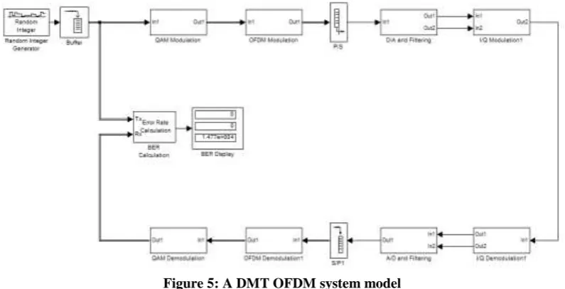
An I/Q modulation OFDM system model developed with the Matlab/Simulink software is shown in figure 5 below;
Figure 5: A DMT OFDM system model
(a)
(b)
(c)
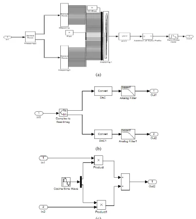
Figure 6: (a) Symbol Mapping, Inverse Fast Fourier Transform (IFFT) Operation and the addition of Cyclic Prefix in the OFDM Modulation block in figure 5(b) Digital to Analogue (D/A) Conversion and Analogue Filteringin the D/A and filtering block in figure 5(c) I/Q Modulation in the I/Q Modulation 1
block in figure 5
Figure 6(a) shows the Symbol Mapping, Inverse Fast Fourier Transform (IFFT) Operation and the addition of Cyclic Prefix for the I/Q modulation model, its different from the DMT case as there is no need to introduce a Hermitian Symmetry in the symbol mapping. The complex term generated by the QAM modulation is separated into real and imaginary parts as shown in figure 6 (b) before a DAC conversion and analogue filtering. The I/Q modulation is shown in figure 6 (c). The received signal is detected and an error rate calculation takes place at the receiver section where a reverse operation takes place. Also, there was no error in the model because a no-noise/channel scenario was assumed in order to ascertain the accuracy of the model [3].
III.
CONCLUSION
REFERENCES
[1]. Hashemi, S.K., et al. Orthogonal frequency division multiplexing for indoor optical wireless communications using visible light LEDs. in Communication Systems, Networks and Digital Signal Processing, 2008. CNSDSP 2008. 6th International Symposium on. 2008.
[2]. Afgani, M.Z., et al. Visible light communication using OFDM. in Testbeds and Research Infrastructures for the Development of Networks and Communities, 2006. TRIDENTCOM 2006. 2nd International Conference on. 2006.
[3]. Armstrong, J., OFDM for Optical Communications. Lightwave Technology, Journal of, 2009. 27(3): p. 189-204.
[4]. Xiao, Y., Orthogonal Frequency Division Multiplexing Modulation and Inter-carrier Interference Cancellation. 2003, Louisiana State University and Agricultural and Mechanical College: Louisiana.
[5]. Elgala, H., et al. OFDM Visible Light Wireless Communication Based on White LEDs. in Vehicular Technology Conference, 2007. VTC2007-Spring. IEEE 65th. 2007.
[6]. Bingham, J.A.C., Multicarrier modulation for data transmission: an idea whose time has come. Communications Magazine, IEEE, 1990. 28(5): p. 5-14.
[7]. Elgala, H., R. Mesleh, and H. Haas. Practical considerations for indoor wireless optical system implementation using OFDM. in Telecommunications, 2009. ConTEL 2009. 10th International Conference on. 2009.
[8]. Ntogari, G., et al., Combining Illumination Dimming Based on Pulse-Width Modulation With Visible-Light Communications Based on Discrete Multitone. Optical Communications and Networking, IEEE/OSA Journal of, 2011. 3(1): p. 56-65.
[9]. Elgala, H., R. Mesleh, and H. Haas, Indoor broadcasting via white LEDs and OFDM. Consumer Electronics, IEEE Transactions on, 2009. 55(3): p. 1127-1134.
![Figure 2: OFDM subcarrier signals (frequency spectrum) [4]](https://thumb-us.123doks.com/thumbv2/123dok_us/1368210.1646523/2.595.118.479.119.298/figure-ofdm-subcarrier-signals-frequency-spectrum.webp)