Computational Fluid Dynamic Analysis Of The
Effect Of Kink Conduit In Microvascular Vein
Grafting
M. N. Rahman Y.
a,*, Shahriman A.B.
a,**, SK Za‘aba
a, SA Roohi
b, Khairunizam WAN
a,
M. Nasir Ayob
a, A.H. Ismail
aa
School of Mechatronic Engineering, Universiti Malaysia Perlis, Main Campus Pauh Putra, Perlis, Malaysia, 02600
b
Orthopedics Department, Faculty of Medicine and Health Sciences, Universiti Putra Malaysia, Serdang, Selangor, Malaysia, 43400
*[email protected],**[email protected]
Abstract— Arterial disease of the upper extremity is an uncommon occurance, most commonly caused by atherosclerosis.In some patients with arterial disease, surgical bypass by vein grafting or vein interposition may be performed. However, due to the length kink between the existing artery and applied vein graft or more of the length of the applied vein graft may get blocked or severely narrowed. The objective of this study is to investigate the influence of blood flow on a failed vein graft due to length kink. The 3-D computational fluid dynamic method was employed to determine pulsatile flow velocity, pulsatile pressure gradient, and wall shear stress impact on the mismatched diameter of artery-vein graft model. We expect that pulsatile flow velocity, pulsatile pressure gradient and wall shear stress impact on mismatched diameter of artery-vein graft model to behave non-hydraulically compared to an ideal length model.
Index Term-- vein graft survival; digital artery disease; upper extremity; computational fluid dynamic; numerical method
I. INT RODUCT ION
Atherosclerosis formation in upper e xt re mity is uncommon compared to vascular disease in lower e xt re mity [1, 2]. It causes a narrowing of the lu men of the blood vessel and also an increase in the blood vessel wa ll stiffness or decrease in compliance of the blood vessel. In some patients who suffer with arterial d isease, surgical vein bypass or interposition vein grafting is performed to overcome the block especially in digital a rtery [1, 3-5]. In 1906, Ca rre l and Guthrie have performed the first successful application of blood vessel repair [6]. In the surgerica l technique, the thro mbosed artery segment is e xc ised, and the harvested saphenous vein graft is inserted reversed [7, 8].Su itable veins are available on the volar aspect of the forearm or on the dorsum of the foot and ankle [8, 9].
One of the require ments is that the vein graft should have approximately the same dia meter and the sa me length as the previously exc ised artery segment [9].Thus saphenous vein have been proposed as an ideal vein for gra fting [ 8-14]. There are several reasons for this. First, because of its relative ly large dia meter and wall characteristics, it is technically easy to use; second, it is plentiful, and therefore can be used to perform mu lt iple gra fts; third, it is long and can reach any artery; and fourth, it is easily harvested [15]. However, despite the initial success of procedure performed
by surgeon, its durability and longevity are still unpredictable, and many vein graft failure cases that have still been reported [1, 7, 8, 15]. Most defected finger was cool and pale [1-3, 16-17]. Furthermore, it is depending on surgeon‘s skill and meticulous surgical technique to ensure clean and matching vein graft stitching [8, 12, 15].
Based on previous study, a kinking of the vein [9,14,18] as well as mis matched internal dia meter of end-to end vein graft [9,13,19, 20] causes vein graft failure. In fact, the length and internal d ia meters of the vein are strongly related to the vein graft lifespan [21, 22]. He modyna mics including blood flow pattern, velocity, pressure gradient, strain rate, and shear stress impact on vessel wall has been believed to affect the development and progression of arterial stenosis but previous studies lack of realistic physiological considerations such as irregular vein geo metry formation, flow pulsatility, especially in the mic rovascular vein grafting. The objective of this study to investigate the relationships between kink ve in graft and thro mbosis in microvessels with low Reynolds blood flows.
The three dimensional CFD (co mputational flu id dynamic ) analysis were applied to calculate blood flow ve locity, pressure gradient in blood flow along the vein gra ft model, resistance of blood flow through vein graft model and wa ll shear stress impact on vein graft wall consist of the searching of flow patterns in a given ideal and kink vein model and applying the boundary conditions for flow variables. The co mputational fluid dyna mic techniques were also used previously to investigate the hemodynamic factors such as deformat ion erythrocytes [15-19], blood viscosity [20, 22], wall shear stress impact on vessel wall [20,21], and blood flow ve locity [20,21,24,25] in the comp le x three-dimensional blood mic rovessels. Those studies demonstrated that the computational fluid dyna mic approach can provide the motion informat ion of blood flow flowing in the microvessel models.
straight vein graft model (0°) a lso have been proposed as an ideal vein graft for co mparison with the kink vein graft model since any flu id flows in straight tube provided very accurate fluidic properties [10,13,14,36-38].
II. RESEARCH MET HODOLOGY
The basic concept in modeling vein graft blood flow is by applying the diffe rent e xisting artery dia meter that attached with the same dia meter of vein graft. The three dimensional Navier-stokes equation is used in the three dimensional vein graft geo metry model. The energy equation was ignored in this study since we were only concentrating our study blood flow in vein graft model.
The blood flow in microvessels has been modeled as three dimension flow in a rigid wall, and governing equations, the
incompressible Navier-Stokes equations, are expressed as :
(
)
( )
(1)
(
)
( )
(2)
(
)
(
) (3)
Where t is time, ρ is the density, p is the pressure, μ is the viscosity. The blood velocity components in x, y and z
directions are denoted as u, v and w. The components of gravity effect in these directions are denoted by gx, gy, and gz respectively. Each node from meshing cell of three dimensional meshing of the three dimensional vein g raft geometry imp le mented the above differentia l equations. In this study, the gravity effect was a lso ignored.All analysis simu lation works we re done by ANSYS Fluent Inc. comme rcia l co mputational fluid dynamic software application.
A. Kink model
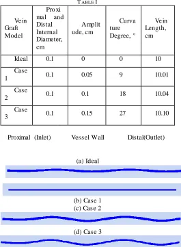
The dimension of the conduits, namely the saphenous vein graft was obtained from [9, 34]. The three-dimensional geometry of the saphenous vein graph model (Fig. 1) was constructed using the commerc ial fluid dynamic software GAM BIT. The graft length and diameter is provided in Table I
TABLE I
Ve in Graft Model
Pro xi ma l and Distal Internal Dia meter, cm
Amplit ude, cm
Curva ture Degree, °
Ve in Length, cm
Ideal 0.1 0 0 10
Case
1 0.1 0.05 9 10.01
Case
2 0.1 0.1 18 10.04
Case
3 0.1 0.15 27 10.10
Proximal (Inlet) Vessel Wall Distal(Outlet)
(a) Ideal
(b) Case 1 (c) Case 2
(d) Case 3
Fig. 1. Figure of geometry of vein graft model (a) Ideal; (b) Case 1; (c) Case 2; (d) Case 3
B. Meshing Grid and Boundary Condition
To nume rica lly ca lculate b lood flow through the each vein graft model, a simulat ion and every boundary condition need to be set for each reg ion. All meshing grid in vein g raft geometry models are divided into a number of finite computational volu mes or cells. The equations are non-linear, unsteady and comple x, several iteration of the solution loops were needed before a solution result was fully converged. Once calculation was converged after some iteration, the co mputed solution provides flow -variab le values at the each cell in the grid.
By applying this approach, the resultant algebraic equations for the dependent variables (the blood flow velocit ies) in each control volume we re solved by a Least Squares Cell Based for linear equation solver and discretizations method. The calculat ion was ca rried out by setting the convergence criteria as 10-6.
The governing equations were calculated rap idly until calculations of all flow variables were converged on a HP workstation Z600 desktop (Intel Xeon, 4 GB RAM). The number of ma ximu m over iterations was set as 40. The size time steps were 1 and the size steps were set as 10s.
Fig. 2. Figure of location of boundary conditions on the vein graft model
C. Proximal Boundary Condition
As a blood flow is a laminar flow at the inlet of vein graft geometry models; that is, the blood is at all point moving parallel to the walls of the vessel, so that:
( )
Where u is the velocity, do is the internal dia meter of the whole vein graft model (0.1 c m) and d is the diameter location as measured from the center of the boundary wall surface.
The inlet velocity boundary conditions to the model of pulsatile flo w where they were 6.25c m/s as dias tolic phase, 12.50c m/s as mean velocity and 18.75c m/s as systolic phase and were set as a velocity-inlet zone.
D. Distal Boundary Condition
The zone for the outlet boundary conditions to the model were set as a pressure-outlet.
E. Vessel Wall Boundary Condition and Assumption
The vessel wa ll is long, cylindrica l shape, rigid body; the dia meter does not vary with the internal blood pressure and were set as a wall zone.
F. Blood Density and Viscosity
The blood is ho mogenous and its viscosity is the same at a ll rates of shear and does not slip at the wall. For mode ling purpose, a constant density of blood is 1050 kg/ m3 and viscosity is 0.0035 kg/ms.
III. RESULT AND DISCUSSION
As blood flow in d igita l arteries is not steady, t≠0, one of the
basic assumptions of deriving the Poiseuille equation is breached. Thus it is to be anticipated that the velocity profile will not be the same parabolic form that is found in steady la minar flo w, t=0 [32].The equation for the motion of a viscous liquid in la minar flow in a tube of circular c ross section, radius R, was derived earlie r for steady flow, t=0 [32]. In its general form for an inco mpressible liquid, we can write
(Wome rsley,1955a ,b, 1957a) [32]. Following co mmon convention, the axis of the vein gra ft is taken as x a xis and the blood velocity in the direction of that is u m/s (the velocities in the y and z a xis for a rig id body of vein g raft will both be zero [32]. In this study, we observed the blood flow characteristic in the vein g raft models after calcu lations were co mpleted. For b lood flow ve locity observation, we chose the computed velocity at pro ximal (inlet ) and distal (outet) of every case, Ideal, Case 1, Case 2 and Case 3.
A. Velocity Profile Observation Of Pulsatile Blood Flow
(a)
(b)
(c)
0 0.05 0.1 0.15 0.2
0 5 10 15
Ve locity, m/s
Time , s
Velocity Profile In Ideal
Proximal
Distal
0 0.05 0.1 0.15 0.2
0 5 10 15
Ve locity, m/s
Time , s
Velocity Profile In Case 1
Proximal
Distal
0 0.05 0.1 0.15 0.2
0 5 10 15
Ve locity, m/s
Time , s
Velocity Profile In Case 2
Proximal
Distal
Proximal
Vessel Wall
Distal
Vessel Wall
(d)
Fig. 3. Figure of velocity profile of vein graft model (a) Ideal; (b) Case 1; (c) Case 2; (d) Case 3
Fro m our observation on velocity profile at pro xima l and distal position, we can see that velocities profile at in a ll three cases are same.
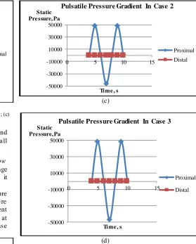
B. Pressure Gradient Observation Of Pulsatle Blood Flow
Flow pressure gradient is the how the flow pressure change with e levation meaning the flow pressure decreases as it move forward or upward.
In this study, we observed the pulsatile flo w pressure gradient in the ve in gra ft models a fter ca lculations we re completed. Fo r the pulsatile flow pressure gradient observation, we chose the computed pulsatile pressure at proxima l (in let) and distal (outet) of every case, Ideal, Case 1, Case 2 and Case 3.
(a)
(b)
(c)
(d)
Fig. 4. Figure of pulsatile pressure gradient of vein graft model (a) Ideal; (b) Case 1; (c) Case 2; (d) Case 3
Fro m our observation on pulsatile pressures at pro xima l and distal positions, we can see that the highest
reduction in the amplitude of flow wave is for Case 1, Case 2 and Case 3 as co mpare to the Ideal. This is due to the blood being pushed (force through) at higher speed fro m the arteria l vessels to the curved vein grafted vesselscausinga high reduction in the a mplitude of flo w waves [32]. Alterations of pulsatile pressure gradient also can be related to vein graft life span [21].
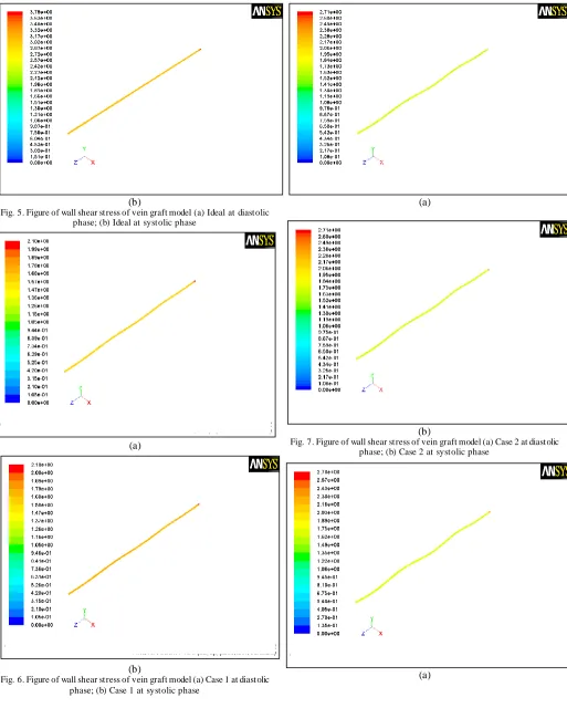
C. Shear Stress Observation Of Vessel Wall
Wall shear stress influences vascular bio logy in many ways. We continue our study by the observation of wall shear stress impact on vein graft wa ll by observation in all vein graft model. We can see that the highest wall shear stress impact occurs in the ideal case only.
(a)
0 0.05 0.1 0.15 0.2
0 5 10 15
Ve locity, m/s
Time , s
Velocity Profile In Case 3
Proximal
Distal
-50000 -30000 -10000 10000 30000 50000
0 5 10 15
Static Pre ssure, Pa
Time , s
Pulsatile Pressure Gradient In Ideal
Proximal
Distal
-50000 -30000 -10000 10000 30000 50000
0 5 10 15
Static Pre ssure, Pa
Time , s
Pulsatile Pressure Gradient In Case 1
Proximal
Distal
-50000 -30000 -10000 10000 30000 50000
0 5 10 15
Static Pre ssure, Pa
Time , s
Pulsatile Pressure Gradient In Case 2
Proximal Distal
-50000 -30000 -10000 10000 30000 50000
0 5 10 15
Static Pre ssure, Pa
Time , s
Pulsatile Pressure Gradient In Case 3
Proximal
(b)
Fig. 5. Figure of wall shear stress of vein graft model (a) Ideal at diastolic phase; (b) Ideal at systolic phase
(a)
(b)
Fig. 6. Figure of wall shear stress of vein graft model (a) Case 1 at diastolic phase; (b) Case 1 at systolic phase
(a)
(b) (b)
Fig. 7. Figure of wall shear stress of vein graft model (a) Case 2 at diastolic phase; (b) Case 2 at systolic phase
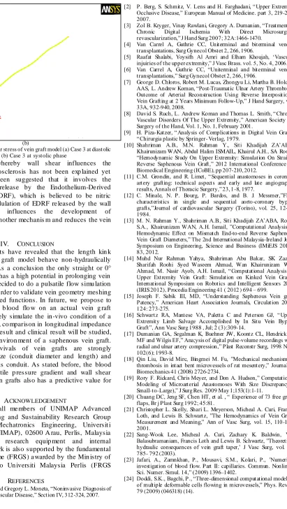
(b)
Fig. 8. Figure of wall shear stress of vein graft model (a) Case 3 at diastolic phase; (b) Case 3 at systolic phase
The mechanism whereby wall shear influences the occurrence of atherosclerosis has not been exp lained yet however, it has been suggested that it involves the regulation of the release by the Endothelium-De rived Re la xing Factor (EDRF), which is believed to be nitric oxide [32]. The modulation of EDRF re leased by the wall shear stress also influences the development of atherosclerosis via another mechanis m and reduces the vein graft life span.
IV. CONCLUSION
The computed results have revealed that the length kin k between artery-vein graft model behave non-hydraulically like an ideal case. As a conclusion the only straight or 0° curvature vein graft has a high potential in prolonging vein graft survival. We decided to do a pulsatile flow simu lation in a straight tube in o rder to validate vein geo metry meshing and input user defined functions. In future, we propose to investigate pulsatile b lood flo w on an actual vein g raft model so as to closely simulate the in-vivo condition of a vein graft. After that, co mparison in longitudinal impedance between simulation result and clinical result will be studied, perhaps in a local environ ment of a saphenous vein graft. The long-term survivals of vein grafts are strongly dependent on the size (conduit dia meter and length) and quality of the venous conduit. As stated before, the blood flow velocity, pulsatile p ressure gradient and wall shear stress impact on vein grafts also has a predictive value for vein graft survival.
V. ACKNOWLEDGEMENT
Special thanks to all me mbe rs of UNIMAP Advanced Intelligent Co mputing and Sustainability Research Group and School Of Mechatronics Engineering, Universit i Malaysia Perlis (UNIMAP), 02600 A rau, Perlis, Malaysia for providing the research equip ment and internal foundation. This work is also supported by the fundamental research grant scheme (FRGS) a warded by the Min istry of Higher Education to Un iversiti Malaysia Perlis (FRGS 9003-00313).
REFERENCES
[1] Jocelyn A. Segall and Gregory L. Moneta, ―Noninvasive Diagnosis of Upper Extremity Vascular Disease,‖ Section IV, 312-324, 2007.
[2] P. Berg, S. Schmitz, V. Lens and H. Farghadani, ―Upper Extremity Occlusive Disease,‖ European Manual of Medicine. part 3, 219-236, 2007.
[3] Zol B. Kryger, Vinay Rawlani, Gregory A. Dumanian, ―Treatment of Chronic Digital Ischemia With Direct Microsurgical revascularization,‖ J Hand Surg 2007; 32A:1466-1470.
[4] Van Carrel A, Guthrie CC, Uniterminal and biterminal venous transplantations, Surg Gynecol Obstet 2, 266, 1906.
[5] Raafat Shalabi, Yoysifh Al Amri and Elham Khoujah, ‗Vascular injuiries of the upper extremity,‖ J Vasc Brass. vol. 5, No. 4, 2006. [6] Van Carrel A, Guthrie CC, ―Uniterminal and biterminal venous
transplantations,‖ Surg Gynecol Obstet 2, 266, 1906.
[7] George D. Chloros, Robert M. Lucas, Zhongyu Li, Martha B. Holden, AAS, L. Andrew Koman, ―Post-Traumatic Ulnar Artery Thrombosis: Outcome of Arterial Reconstruction Using Reverse Interposit ional Vein Grafting at 2 Years Minimum Follow-Up,‖ J Hand Surgery, vol. 33A, 932-940, 2008.
[8] David S. Ruch, L. Andrew Koman and Thomas L. Smith, ―Chronic Vascular Disorders Of The Upper Extremity,‖ American Society for Surgery of the Hand, Vol. 1, No. 1, February 2001.
[9] H. Piza-Katzer, ― Analysis of Complications in Digital Vein Grafts, ―Chirurgia plastic by Springer- Verlag, 1979.
[10] Shahriman A.B., M.N. Rahman Y., Siti Khadijah ZA‘ABA, Khairunizam WAN, Abdul Halim ISMAIL, Khairul A.H., SA Roohi, ―Hemodynamic Study On Upper Extremity: Simulation On Straight Reverse Saphenous Vein Graft,‖ 2012 International Conference on Biomedical Engineering (ICoBE), pp 207-210, 2012.
[11] C.M. Grondin, and R. Limet, ―Sequential anastomoses in coronary artery grafting: technical aspects and early and late angiographic results, Annals of Thoracic Surgery,‖ 23, 1-8, 1977.
[12] C. Minale, N. P. Bourg, P. Bardos, and B. J. Messmer,‖Flow characteristics in single and sequential aorto-coronary bypass grafts,‖Journal of cardiovascular Surgery (Torino), vol. 25, 12-15, 1984.
[13] M. N. Rahman Y., Shahriman A.B., Siti Khadijah ZA‘ABA, Roohi S.A., Khairunizam WAN, A.H. Ismail, ‖Computational Analysis of Hemodynamic Effect on Mismatch End-to-end Reverse Saphenous Vein Graft Diameters,‖ The 2nd International Malaysia-Ireland Joint Symposium on Engineering, Science and Business (IMiEJS 2012), 83, 2012.
[14] Muhd Nur Rahman Yahya, Shahriman Abu Bakar, SK Zaaba, Sharifah Roohi Syed Waseem Ahmad, Wan Khairunizam Wan Ahmad, M. Nasir Ayob, A.H. Ismail, ―Computational Analysis on Upper Extremity Vein Graft: Simulation on Kinked Vein Graft,‖ International Symposium on Robotics and Intelligent Sensors 2012 (IRIS 2012), Procedia Engineering 41 ( 2012 ) 694 – 699.
[15] Joseph F. Sabik III, MD, ―Understanding Saphenous Vein graft Patency,‖ American Heart Association Journals, Circulation 2011; 124: 273-275.
[16] Schwartz RA, Mantese VA, Paletta C and Peterson GJ, ―Upper Extremity Limb Salvage Accomplished by In Situ Vein Bypass Graft‖, Ann Vasc Surg 1988 , Jul; 2 (3):309-14.
[17] Dumanian GA, Segalman K, Buehner JW, Koontz CL, Hendrickson MF and Wilgis EF,‖ Ana;ysis of digital pulse-volume recordings with radial and ulnar artery compression,‖ Plast Reconstr Surg, 1998 Nov; 102(6); 1993-8.
[18] Qin Liu, David Mirc, Bingmei M. Fu, ‖Mechanical mechanism of thrombosis in intact bent microvessels of rat mesentery,‖ Journal of Biomechanics 41 (2008) 2726-2734.
[19] Rory F. Rickard, Chris Meyer, and Don A. Hudson,‖ Computational Modeling of Microarterial Anastomoses With Size Discrepancy ( Small-to-Large),‖ J Surg Res. 2009 May 1;153(1):1-11.
[20] Chuang DC, Jeng SF, Chen HT, et al. , ― Experience of 73 free groin flaps, Br j Plast Surg 1992; 45:81.
[21] Christopher L. Skelly, Shari L. Meyerson, Micheal A. Curi, Francis Loth, and Lewis B. Schwartz, ‖The Hemodynamics of Vein Graft: Measurement and Meaning,‖ Ann of Vasc Surg, vol. 15, 110-122, 2001.
[22] Sang-Wook Lee, Micheal A. Curi, Zachary K. Baldwin, Viji Balasubramaniam, Francis Loth and Lewis B. Schwartz, ‖Theoretical hydraulic consequences of vein graft taper,‘ J Vasc Surg, vol. 38, 785- 792 (2003).
[23] Jafari, A., Zamnkhan, P., Mousavi, S.M., Kolari, P., ‘Numerical investigation of blood flow. Part II: capillaries. Commun. Nonlinear Sci. Numer. Simul. 14,‖ (2009) 1396–1402.
[25] Secomb, T.W., Styp-Rekowska, B., Pries, A.R., ―T wo-dimensional simulation of red blood cell deformation and lateral migration in microvessels,‖ Ann. Biomed. Eng. 35, 755–765, 2007.
[26] Filipovic, N., T suda, A., Lee, G.S., Miele, L.F., Lin, M., Konerding, M.A., Mentzer, S.J., 2009, ‗Computational flow dynamics in a geometric model of intussusceptive angiogenesis,‖ Microvasc. Res. 78, 286–293, 2009.
[27] Jung, J., Hassanein, A., ―Three-phase CFD analytical modeling of blood flow,‖ Med. Eng. Phys. 30, 91–103, 2008.
[28] Cole, J.S., Watterson, J.K., ―Blood flow characteristics in a femoral artery bypass graft,‖ Dev. Chem. Eng. Miner. Process. 11, 15–28, 2003.
[29] Klyscz, T ., Jünger, M., Jung, F., Zeintl, H., ― Cap image – a new kind of computer assisted video image analysis system for dynamic capillary microscopy (in German),‖ Biomed. Tech. (Berl) 42, 168– 175, 1997.
[30] Tzu-Ching Shih, Geoffrey Zhang, Chih-Chieh Wu, Hung-Da Hsiao, T sung-Hsin Wu, Kang-Ping Lin, Tzung-Chi Huang, ―Hemodynamic analysis of capillary in finger nail-fold using computational fluid dynamics and image estimation,‖ Microvascular Research 81, 68-72, 2011.
[31] Mette S. Olufsen, Charles S. Peskin, Won Yong Kim and Erik M. Pederse, Ali Nadim, Hesper Larsen, ―Numerical Simulation and Experimental Validation of Blood Flow in Arteries with Structured-Tree Outflow Conditions,‖ Annals of Biomedical Engineering, Vol. 28, pp.1281–1299, 2000.
[32] Wilmer W Nichols, Micheal F O‘rourke, Craig Hartley, ―McDonald‘s Flow in Arteries: Theoretical, experimental and clinical principles 4th Edition,‖ Fourth Edition published in 1998 by Arnold, a member of the Hodder Headline Group, 338 Euston Road, London NW1 3BH [33] Meena S, Dhanjoo N Ghista, Poh Chua and T an Yong Seng,
―Numerical Investigation of Blood Flow in a Sequential Aorta-Coronary Bypass Graft Model,‖ Conf Proc IEEE Eng Med Biol Soc., 1:875-8, 2006.
[34] Ying He, Hao Liu, Ryutaro Himeno, ―A one-dimensional thermo-fluid model of blood circulation in the human upper limb,‖ International Journal of Heat and Mass Transfer 47, 2735-2745, 2004. [35] GJ T angelder, DW Slaaf, AM Muijtjems, T Arts, MG oude Egbrink and RS Reneman, ― Velocity profiles of blood platelets and red blood cells following in arterioles of rabbit mesentery,‖ Circ Res. 59:505-514, 1986.
[36] Donald F. Young, Bruce R. Munson, Theodore H. Okiishi and Wade W. Huebsch. ― A Brief Introduction to Fluid Mechanics 4th Edition,‖ by John Wiley & Sons Inc; 3rd International edition edition, 2003. [37] Lee Waite, ―Biofluid Mechanics in Cardiovascular Systems,‖
McGraw-Hill's Biomedical Engineering, 2005.