1
Application of directional borehole grouting technology to structural
complex floor reinforcement in deep underground coal mine
Qiqing Wang · Wenping Li*
School of Resources and Geosciences, China University of Mining and Technology, Xuzhou 221116,
China.
Correspondence: [email protected]
Abstract Water inrush from coal floor constitutes one of the main disasters in mine
construction and mine production, which always brings high risks and losses to the coal mine
safe production. As the mining depth of coal fields in North China gradually increased,
especially in the complicated structural region, the threat posed by limestone karstic water of
coal floor to the safe stoping of mines has become increasingly prominent. In this paper, the
Taoyuan coalmine was taken as an example, for which, the directional borehole grouting
technology was utilized to reinforce the coal seam floor prior to mining. Also, the factors
affecting the grouting effect were analyzed. These were the geological structure, the crustal
stress and the range of slurry diffusion. The layout principle of grouting drilling was put
forward and the directional drilling structure was designed. The water level observations in
the end hole indicated that the target stratum was accurate and reliable. The effect of grouting
was validated through the audio frequency electric perspective method and the holedrilling in
the track trough. The results demonstrated that the effect of grouting in third limestone and the
rock stratum above the third limestone of coal seam floor was apparent. Simultaneously, no
water inrush occurred following the actual mining of the working face, which further
demonstrated that the grouting reinforcement effect was apparent. The research findings were
of high significance for the prevention and control of floor water disaster and water
conservation in deep complex structural areas.
1. Introduction
China is globally the producer and consumer of the highest amount of coal. A high number of
disasters occur in the coalmines of China every year, in which water inrush is one of the major
disasters. According to statistics, since 2000, more than 750 coal mine water inrush accidents
occurred in China, while more than 3800 people died, resulting in direct economic losses,
exceeding tens of billions of dollars (http://www.chinacoal-safety.gov.cn/mkaj/). As the
mining depth of coal fields in North China gradually increases, the risk of water inrush in
deep mines increases due to the effects of excavation disturbance and the inaccuracy of
invisible water conducted structure exploration (For example, the detection rate of the
collapse column can only reach to approximately30%) (Sui et al. 2011; Li and Chen 2016;
Sun et al. 2017). In particular, the lower-group coal mining in the North China coalfield,
which is threatened by the karst water of the coal floor limestone, often causes catastrophic
water inrush accidents as a result of the strong conducting-water structure zone (collapse
column and concentrated fracture zone of structure) (Meng et al. 2009; Hu et al. 2014; Shi et
al. 2017; Yang et al. 2017).
At present, the main methods for the prevention and control of limestone karst water in coal
mines include drainage to lower water pressure and grouting reconstruction (Ge and Wang
2007; Wang et al. 2012; Cheng et al. 2013; Hao et al. 2014; Li and Du 2014; Tian et al. 2015;
Sun et al. 2015). The drainage to lower water pressure method refers to the drainage of the
aquifers in the floor prior to coal mining. This method is easily restricted by the water content
of the aquifer, the condition of recharge, the thickness of floor aquiclude, the pressure and the
drainage capacity of the mine, causing high amounts of groundwater waste. Conventional
grouting reconstruction is mainly conducted through grouting in the underground tunnel or
ground drilling, the plugging of fractures of the floor rock stratum and the tensile strength
increase of the floor, to overcome the pressure of confined water and prevent water inrush
from the working face. This method is difficult and inefficient due to underground grouting
construction, while its effect is versatile. In addition, for ground drilling grouting, due to the
2014).
To solve the problem of water inrush from coal floor as well as the shortage of
conventional drilling grouting, in this paper, the Taoyuan coalmine was taken as an example.
The directional borehole grouting technology was utilized to reinforce the coal seam floor
prior to mining, to prevent and control the karst water disaster of the floor limestone. The
layout principle and structure of the directional drilling were studied. The grouting effect was
verified through geophysical prospecting and holedrilling in the track trough. The research
findings were of high significance for the prevention and control of floor water disaster and
water conservation in deep complex structural areas.
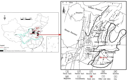
2 Study Area
The Huaibei coal mine district is located in the northern part of Anhui province. It lies at the intersection of the four provinces of Jiangsu, Shandong, Henan and Anhui, where as the geotectonic position is in the southeast margin of the North China plate. The east-west direction of the mining area is approximately140km.The north-south direction is
approximately110km, while the entire area is approximately 15400km2.The coal resources in the mining area are abundant and the coal quality is good. The entire region constitutes an important coal gathering area of the Carboniferous Permian system in China (Fig. 1).
The fault structures in the mining area have developed (More than 600 faults were found, of which, 170 exceeded 100m in drop height), while the mining geology and hydrogeological conditions are complex. The lower-groups of coal (6thand 10th) seams are mainly threatened by the thin limestone group (first limestone to fourth limestone) in the upper part of the Taiyuan formation and the deep Ordovician aquifer. The limestone of Taiyuan formation is mainly a medium - thin layer limestone, mainly with fractured karst water and the
water-abundance is quite uneven. Most regions are characterized by high pressure and water-abundance as the depth increases. The distance between the coal seam and the
520m), the water pressure increases, easily causing the high-sized Ordovician limestone water inrush into the mine, leading to mine disasters and major losses. In mines such as Yangzhuang, Taoyuan and Zhuzhuang, similar water inrush accidents have occurred.
Taking the Taoyuan coalmine as an example, the directional borehole grouting technology was utilized to reinforce the coal seam floor prior to mining, to prevent and control the karst water disaster of the floor limestone. The Taoyuan coalmine is located in the south of the Huaibei mining area (Fig. 1). The structural complexity of the study area was medium, presenting 12 faults at the drop height of beyond or equal to 10m, while the low-sized structures of the study were developed.
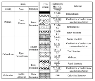
The third limestone in the study area was the thin limestone aquifer with the highest water abundance in the first limestone to the fourth limestone of the upper part of the Taiyuan formation, also constituting one of the main direct discharge aquifers for the 10th coal seam (Fig. 2). The grouting to reinforce third limestone could directly fill the thin layer limestone karst fracture. The third limestone had a high amount of fractures and strongly pourable. Consequently, it was easy to achieve the expected grouting reinforcement effect. Therefore, the third limestone was selected as the target layer for grouting reinforcement.
2.2~4.0 3.7 Strata
System Series Formation Core columns Thickness (m) Min~Max Average Lithology Permain Carboniferous Ordovician Lower Permian Upper Carboniferous Middle Ordovician 56.0~59.8 57.9 2.1~3.0 2.6 3.9~5.0 4.5 3.0~4.8 3.9 5.8~6.5 6.2 6.5~13.1 9.8 3.2~5.0 4.1 3.5~8.7 6.1 59.2~61.3 60.3 >500 Shanxi Formation Taiyuan Formation Benxi Formation Baitu Formation
10th coal seam
Combination of mud rock and sandstone interbedded Sandy mudstone Second limestone Ordovician limestone First limestone Third limestone Fourth limestone Mudstone
Combination of mud rock and sandstone interbedded Combination of mud rock and
sandstone interbedded
Fig. 2 Comprehensive typical strata column of coal seam floor for study area
3 Directional borehole design
3.1 The layout orientation of grouting drilling
3.1.1 Effect of geological structure on drilling orientation selection
The fractures, the faults, the water rich zone and the vertical water conducting structure zone
of the third limestone in the coal seam floor were the object of the ground directional borehole
grouting. Especially, the vertical water fault and the fold axis crack were the key points for the
prevention and control of water inrush from the floor. Faults and their sides are usually
accompanied by many structural fractures, forming tectonic fracture zones. Due to the strong
interlayer shear in the formation of folds, the bedding joints of the limbs were developed. The
lateral side of the turning end was subjected to tension and mainly distributed to tension joints.
The core of the fold was strongly extruded, while the main distribution of the axial plane was
cleavage.
The effects of fault and fold axis should be fully taken into account when the layout
orientation of grouting drilling was designed. For the fissure-cavern limestone, between the
transverse and longitudinal directions significant differences were displayed. If the horizontal
which will be unfavorable for the grouting reconstruction to the water plugging. If the
horizontal section of a single drill is set along the vertical fissure tendency, it will penetrate
more cracks, which will be favorable for the slurry diffusion (Fig.3). Therefore, the
directional drilling locus should be highly intersected with the faults and other fractures.
Grouting hole
Fault Faul
t
Grouting hole
Fault
Fig.3 Sketch of grouting effect at different angles of drilling orientation and fault
3.1.2 Effect of crustal stress on drilling orientation selection
The orientation of directional drilling of horizontal section under the condition of complex
stress distribution has a high effect on the direction of the induced grouting crack produced by
high pressure splitting, which determines whether the fracture zone produced by the
high-pressure grouting can be better connected to the natural fissure or not. Therefore, the
stress distribution condition is an important basis for the orientation optimization of
directional drilling of the horizontal section. For the initiation direction of splitting grouting, it
is generally considered that the splitting plane is perpendicular to the minimum principal
stress direction. This means that the initial crack is along the direction of the maximum
principal stress (Lo and Kaniaru 1990; Zhou and Chen 2002). If the directional horizontal
drilling is in accordance with the maximum horizontal principal stress direction, a
longitudinal crack parallel to the drilling direction is produced. If the drilling is perpendicular
to the direction of maximum horizontal principal stress, a transverse crack perpendicular to
the drilling locus is produced (Fig. 4).
The longitudinal cracks are single and distribute along the maximum principal stress
horizontal drilling locus, while the splitting range is higher. The latter is more conducive to
the diffusion of the slurry with high pressure splitting. Therefore, the vertical direction of
maximum principal stress direction is the dominant position of the horizontal drilling locus.
(a) longitudinal fissures parallel to horizontal drilling locus
(b) transverse fissures perpendicular to horizontal drilling locus
Fig. 4 Sketch of relationship between horizontal drilling locus and splitting fissure orientation
3.2 Grouting simulation of fractured rock mass
In the process of slurry flow, the slurry pressure will cause the rock mass deformation, while
the latter will also affect the slurry diffusion distance size and the final grouting effect. In this
study, the geological and hydrogeological conditions of the study area were analyzed. The
effective diffusion radius of the grouting slurry of third limestone was simulated with a two
dimensional realistic failure process analysis code (RFPA2D-Flow) (Tang et al. 1998).
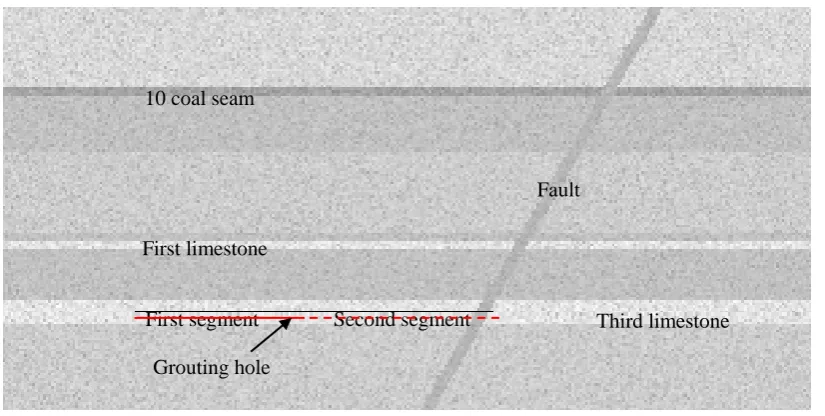
(1) Numerical calculation model and parameters
According to the geological survey data of the study area, the numerical model was
designed (Fig. 5). The size of the model was 300m×150m and the elevation of the 10th coal
floor was approximately -420m. The top and the floor were sandstone and mudstone,
respectively. The third limestone water pressure was approximately 4MPa and the dip angle
of the fault was approximately 60 degrees. The grouting drilling diameter was 152mm.
Based on the measured results of the crustal stress, the applied stress on the left boundary
of the model was 9MPa. The upper boundary of the model as applied to the self-weight load
of the overlying rock and soil (approximately10MPa). The displacements of the right
boundary and the lower boundary were fixed, whereas the upper and lower boundaries of the
second step to simulate grouting. The grouting drilling was set to be conducted at the middle
of the third limestone, while two steps were set to simulate the normal rock layer (first
segment) and fault (second segment) grouting. The length of the grouting section was 60m for
each step. The diffusion rules of the slurries under the four grouting pressures of 4MPa, 8MPa,
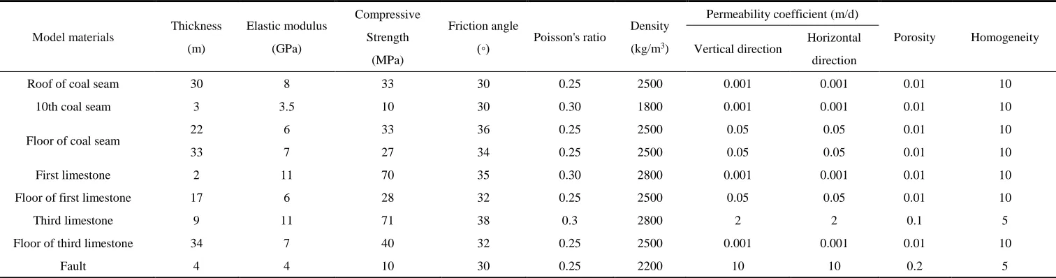
10MPa and 12MPa were simulated. The model parameters of numerical simulation are
presented in Table 1.
Fig. 5 Geological numerical model
First limestone 10 coal seam
First segment Second segment
Grouting hole
Table 1 Model parameters of numerical simulation 1
Model materials Thickness (m)
Elastic modulus (GPa)
Compressive Strength
(MPa)
Friction angle
(◦) Poisson's ratio
Density (kg/m3)
Permeability coefficient (m/d)
Porosity Homogeneity Vertical direction Horizontal
direction
Roof of coal seam 30 8 33 30 0.25 2500 0.001 0.001 0.01 10
10th coal seam 3 3.5 10 30 0.30 1800 0.001 0.001 0.01 10
Floor of coal seam
22 6 33 36 0.25 2500 0.05 0.05 0.01 10
33 7 27 34 0.25 2500 0.05 0.05 0.01 10
First limestone 2 11 70 35 0.30 2800 0.001 0.001 0.01 10
Floor of first limestone 17 6 28 32 0.25 2500 0.05 0.05 0.01 10
Third limestone 9 11 71 38 0.3 2800 2 2 0.1 5
Floor of third limestone 34 7 40 32 0.25 2500 0.001 0.001 0.01 10
Fault 4 4 10 30 0.25 2200 10 10 0.2 5
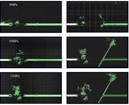
(2) Simulation results and analysis 4
The results of numerical analysis are presented in Figure 6. It could be observed 5
from Figure 6 that when the grouting pressure as 4MPa, the slurry as mainly filled 6
with natural fractures in the aquifer, while the grouting section was partially diffused 7
to the third limestone roof. Also, the diffusion radius was approximately 13m. When 8
the grouting drilling penetrated the fault, the slurry mainly diffused along the fault and 9
the diffusion distance was approximately 60m. 10
When the grouting pressure increased to 8MPa, the diffusion distance of the slurry 11
gradually increased. Moreover, under the action of grouting pressure, the weak 12
structural plane began to expand, especially the bedding, the fault zone and the 13
contact zone. Also, the slurry diffusion radius was approximately 30m. 14
As the grouting pressure continued to increase (10MPa), the stress and tensile 15
strengths of the weak part of the aquifer were exceeded. The splitting formed along 16
the plane perpendicularly to the main stress plane, while the direction of the crack was 17
the same as the direction of maximum principal stress. As the slurry was filled, the 18
aquifer was strengthened further, while the radius of slurry diffusion was 19
approximately 50m. 20
When the grouting pressure increased to 12MPa, the original and split cracks were 21
filled to a relatively high level. As the pressure increased, the filling became dense 22
and the diffusion radius did not increase significantly, while the radius of diffusion 23
slurry was approximately 55m. Adversely, the contact flow between the fault and the 24
coal seam increased. 25
(a) grouting in rock mass (b) grouting in fault
Fig. 6 Results of numerical analysis
26
The aforementioned simulation results demonstrated that the higher the grouting 27
pressure was, the higher the radius of slurry diffusion was, but the diffusion radius 28
increase was not apparent when the grouting pressure reached to a certain pressure 29
value. When the grouting pressure was10~12MPa, the diffusion distance of the slurry 30
changed slightly to approximately 50~55m. On one hand, the diffusion range of the 31
slurry was related to the grouting pressure. On the other hand, the diffusion range of 32
the slurry was related to the dominant direction of fracture. The slurry often diffused 33
along the dominant channel with good permeability and easy splitting of the weak 34
structural planes. 35
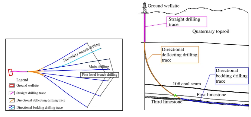
3.3 Drilling structure design 36
The ground directional borehole grouting was mainly through the near horizontal 37
drilling unit to enter the third limestone prior to mining, as well as to seal the cracks 38
with high pressure grouting. The borehole unit was arranged by the main drilling as 39
8MPa
10MPa
well as the multiple first-level branches and secondary branch drilling, which had 40
fan-shaped distribution. The distance in-between branch drillings was 50~110m. The 41
drilling structure design is presented in Figure 7. 42
The drilling consisted of three segments. The first segment was the straight drilling 43
(0~120m). The borehole diameter was 311mm. The size of casing was 244.5mm, 44
putting the casing down to 20m below the bedrock. Cementing was used to isolate the 45
quaternary surface soil layer. The second segment was directional deflecting drilling. 46
The borehole diameter was 216mm, and the size of casing was 177.8mm, putting the 47
casing down to 30m below the floor of 6th coal seam and close to the bedding. The 48
third segment was directional bedding drilling of 152mmin diameter. During driling 49
along the third limestone bedding, all branches sustained directional drilling in the 50
third limestone bedding. 51
Main drilling
Secon dary br
anch dr illing
First-level branch drilling
Ground wellsite
Straight drilling trace
Directional deflecting drilling trace
Directional bedding drilling trace
Legend
Directional bedding drilling trace
10# coal seam
First limestone Third limestone Directional deflecting drilling trace Straight drilling trace Quaternary topsoil Ground wellsite
(a) Plane structure of drilling (b) Section structureof drilling
Fig. 7 Sketch of drilling structure design
52
3.4 Layout of grouting drilling in study area 53
Combined with the aforementioned analysis, it was determined that the orientation 54
and spacing of branch drilling should be based on the following principles: 55
(1) The branch drilling should be intersected with the large angle of fault and folds 56
axis as high as possible, also through the faults and folds. 57
and fault fracture zones, the distance between the branch drilling should not exceed 59
twice the diffusion radius. Simultaneously, the high efficiency and economic 60
rationality should be taken into consideration. The drilling spacing should exceed the 61
single drilling grouting diffusion range. Therefore, the distance between branch 62
drillings should be between 50~110m. 63
(3) The scope of drilling grouting diffusion should cover the entire treatment area 64
as far as possible. 65
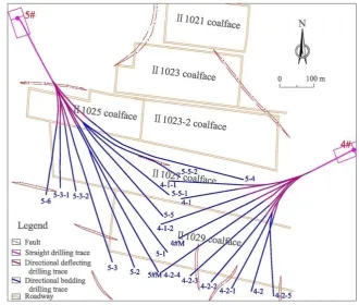
According to the layout principle of the latter grouting drilling, the directional 66
grouting drilling of II1027 and II1029 working faces in the study area was designed 67
and is presented in Figure 8. 68
69
Fig. 8 Layout of grouting drilling in study area
70
4 Grouting and verification of grouting effect
71
4.1 Grouting process 72
The directional drilling grouting of this study was carried out through downward stage 73
grouting and orifice-closed grouting methods (Li and Du 2014), which consisted of 74
two stages: filling grouting and high pressure grouting. 75
the high concentration cement slurry with a specific gravity of 77
approximately1.5~1.7t/m3 is injected with the large displacement grouting pump of
78
260~600L/min to quickly fill the fissure or cave. 79
(2) High pressure grouting: In order to increase the diffusion distance and fill the 80
fine fissures, the high pressure grouting is used to spread the residual gap and 81
low-sized fissure in the rock mass to increase the reinforcement effect. 82
According to the "coal mine prevention and control water regulations" (State 83
Administration of Work Safety 2009), the grouting pressure should be twice the 84
maximum hydrostatic pressure (4MPa) of the injected aquifer, while the termination 85
pressure of the grouting drilling must not be lower than 2.5 times of the water 86
pressure. Due to the particularity of the grouting project, the construction could be 87
adjusted according to the actual situation in the field. The hydrostatic pressure of third 88
limestone was approximately 4MPa.Consequently, the final pressure of grouting 89
was10~12MPa. Finally, the grouting absorption capacity was generally 40~60L/min 90
and the stability time was 20~30 min. 91
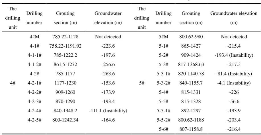
4.2 Verification of grouting effect 92
The water level plays a guiding role in drilling grouting. Through the analysis of 93
the water level and combined with the pressure water testing, the development degree 94
of the fracture, the connection between adjacent aquifers, the existence of abnormal 95
water pressure area, as well as the existence of faults and collapse columns could be 96
determined. Table 2 presents the water levels of each drilling in the II1027 and II1029 97
working faces. In this area, the third limestone water level elevation was usually 98
-180~-230m. It could be observed that the water level of most drillings belonged to 99
the third limestone water level elevation, which demonstrated that the target location 100
of drilling was accurate and reliable, meeting the design requirements. 101
102
Tbale 2 Statistics of water level for each drilling 105 The drilling unit Drilling number Grouting section (m) Groundwater elevation (m) The drilling unit Drilling number Grouting section (m) Groundwater elevation (m) 4#
4#M 785.22-1128 Not detected
5#
5#M 800.62-980 Not detected 4-1# 758.22-1191.92 -223.6 5-1# 865-1427 -215.4 4-1-1# 785-1222.2 -197.6 5-2# 909-1424 -193.4 (Instability) 4-1-2# 861.5-1272 -256.6 5-3# 817-1368.63 -217.3
4-2# 785-1177 -263.6 5-3-1# 820-1140.78 -81.4 (Instability) 4-2-1# 1177-1230 -153.6 5-3-2# 849-1155.7 -4.1 (Instability)
4-2-2# 909-1260 -173.9 5-4# 815-1331 -226
4-2-3# 870-1290 -193.4 5-5# 815-1328 -56.6
4-2-4# 840-1348.2 -111.1 (Instability) 5-5-1# 892-1297 -193.9 4-2-5# 800-1242.34 -164.6 5-5-2# 800.62-1188 -203.4 5-6# 807-1158.8 -216.4
106
Following the completion of grouting, the audio frequency electric perspective 107
(AFEP) method (Zhang et al. 2013) was utilized to detect the grouting face (II1027 108
working face). The results demonstrated that the apparent conductivity was uniformly 109
distributed in most areas of the working face, while the apparent conductivity of the 110
40~70m range below the floor was low. Also, only two relative anomalous regions 111
existed, reflecting the improved effect of the aquifer reconstruction of the floor 112
limestone. 113
Through the drilling of holes in the track trough, the relative anomalous regions of 114
AFEP, the structural fracture development and the abnormal grouting areas were 115
verified. The end position of each drilling was designed as the grouting target layer 116
(middle and lower part of third limestone). The layout of each drilling is presented in 117
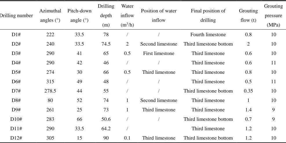
Figure 9. 118
Each drilling was conducted with a 133mm drill, while the casing was put down to 119
2~5m. Consequently, the drill size was changed to 94mm and the casing was put 120
down to 25m. At the end, the 75mm drill was driven to the bottom of the hole. Only 121
six drillings (D2#, D3#, D5#, D8#, D9#, D12#) sent water up in all test drillings, 122
while the amount of water only was 0.5~2.0m3/h. In addition, the D5#, D9# and D12#
drillings sent water up at the third limestone, while the water amounts were 0.5m3/h, 124
1.0m3/h and 0.1m3/h, respectively. The D3# drilling was first limestone with effluent
125
water, while the D#2 andD#8 were second limestone with effluent water. From the 126
aforementioned situation, it could be observed that the third limestone and above the 127
limestone aquifer grouting reconstruction effects were apparent. The first to third 128
limestone could be regarded as the equivalent aquiclude. The grouting sealing was 129
carried out subsequently to the drilling construction, which is referred to Table3. 130
In addition, through actual mining verification, no water inrush occurred during 131
mining, which indicated that the grouting reinforcement effect was apparent. 132
Table 3 List of drilling construction
133
Drilling number Azimuthal angles (°)
Pitch-down angle (°)
Drilling depth
(m)
Water inflow (m3/h)
Position of water inflow
Final position of drilling
Grouting flow (t)
Grouting pressure (MPa)
D1# 222 33.5 78 / / Fourth limestone 0.8 10
D2# 240 33.5 74.5 2 Second limestone Third limestone bottom 2 10 D3# 290 41 65 0.5 First limestone Third limestone 0.6 10
D4# 290 42 46 / / Third limestone 0.6 11
D5# 274 30 66 0.5 Third limestone Third limestone 0.8 10
D6# 315 49 48 / / Third limestone 0.5 11
D7# 278.5 44 55 / / Third limestone bottom 0.35 10
D8# 80 52 74 1 Second limestone Third limestone 1 10
D9# 261 25 73 1 Third limestone Third limestone 1.4 9
D10# 283 66 50.6 / / Third limestone bottom 0.7 9
D11# 290 33.5 64.2 / Third limestone 1.2 10
D12# 305 15 90 0.1 Third limestone Third limestone bottom 1.2 10
135
Fig. 9 Result of AFEP and layout of holedrilling in track trough.
136
5 Conclusions
137
The directional drilling technology and grouting technology were utilized to 138
reconstruct the floor of the typical working face in the deep complex structure mining 139
area of North China.The layout principle of the directional drilling was studied. The 140
borehole unit was arranged through main drilling as well as multiple first-level 141
branches and secondary branch drilling, which had fan-shaped distribution. The 142
geological structure, the crustal stressand the slurry diffusion range were the main 143
factors for the layout consideration of the drillings. The branch drillings were as much 144
as possible through the faults and folds. The spacing of the branch drillings should 145
exceed the single drilling grouting slurry diffusion range, whereas the scope of 146
drilling grouting diffusion should significantly cover the entire treatment area. During 147
grouting in the working faces of the study area, the water level of the grouting branch 148
drilling demonstrated that the target layer of drilling was accurate and reliable, which 149
conformed to the design requirements, indicating that the directional drilling 150
technology was reliable. The AFEP method was utilized to detect the grouting 151
working face. The results demonstrated that the apparent conductivity was uniformly 152
distributed in most areas of the working face, while only two relative anomalous 153
regions existed. Through holedrilling in the track trough, the relative anomalous 154
regionsof AFEP, the structural fracture development and the abnormal grouting areas 155
which indicated that the grouting effects of third limestone and above the limestone 157
aquifer in the study area were apparent. Through actual mining, it was also verified 158
that the grouting reinforcement effect was good. Directional drilling grouting 159
technology had solved the problem of water disasters in the thin aquifer of deep 160
complex structure coal mines, through which, safe mining was realized. 161
Acknowledgments: The authors would like to express their gratitude to everyone who provided
162
assistance for the present study. The study is jointly Supported by "the Fundamental Research 163
Funds for the Central Universities"(grant number 2018QNA43). 164
Author Contributions: This work is the outcome of joint efforts of the two authors, who
165
contributed equally to conceive and design the research. They read and approved the final 166
manuscript. 167
Conflicts of Interest: The authors declare no conflicts of interest.
168
Reference
169
Cheng J, Sun X, Zheng G, Gao F, Kong X (2013) Numerical Simulations of Water-inrush induced 170
by Fault Activation during Deep Coal Mining based on Fluid-Solid Coupling Interaction. 171
Disaster advances, 6(11): 10-14 172
Dong C, Mu P, Li Q, Fang J, Zhao J, Hao Y, Zheng D (2014) Development Trend and Technology 173
of Coal Floor Grouting Reinforcement Drilling Construction. Coal Science and Technology, 174
42(12): 27-31 175
Ge J, Wang J (2007) Application of Stress Release by Lowing Water Pressure to Groundwater 176
Hazard Control in The Work Face in Liuqiao Coal Mine. Coal Engineering, (8): 63-65 177
Hao G, Li H, Du J (2014) Technology combined draining depressurization with floor grouting 178
reconstruction to liberate coal resource being on confined water. Shandong Coal Science and 179
Technology, (7): 154-155 180
Hu X, Wang L, Lu Y, Yu M (2014) Analysis of insidious fault activation and water inrush from the 181
mining floor. International Journal of Mining Science and Technology, 24(4): 477-483 182
GRA–AHP and its application. Geotechnical and Geological Engineering, 34(1): 143-154 184
Li C, Du S (2014) Recovery Working Face Pre-mining Baseboard Grouting Reinforcement 185
Technology Application. Coal and Chemical Industry, 37(11): 70-73 186
Lo KY, Kaniaru K (1990) Hydraulic fracture in earth and rock-fill dams. Canadian Geotechnical 187
Journal, 27(4): 496-506 188
Meng Z, Yi W, Lan H, Wang M (2009) Water in rush characteristics of Fangezhuang coal mine 189
field in Kailuan and its geological condition analysis of water inrush from coal seam floor. 190
Chinese Journal of Rock Mechanics and Engineering, 28(2): 228-237 191
State Administration of Work Safety (2009) Rule of mine prevention and cure water disaster. 192
Beijing: China Coal Industry Publishing House 193
Shi L, Gao W, Han J, Tan X (2017) A Nonlinear Risk Evaluation Method for Water Inrush 194
Through the Seam Floor. Mine Water and the Environment, 36(4): 597-605 195
Sui W, Liu J, Yang S, Chen Z, Hu Y (2011) Hydrogeological analysis and salvage of a deep 196
coalmine after a groundwater inrush. Environmental Earth Sciences, 62(4): 735-749 197
Sun W, Wu Q, Liu H, Jiao J (2015) Prediction and assessment of the disturbances of the coal 198
mining in Kailuan to karst groundwater system. Physics and Chemistry of the Earth, 89: 199
136-144 200
Sun W, Zhang S, Guo W, Liu W (2017) Physical Simulation of High-Pressure Water Inrush 201
Through the Floor of a Deep Mine. Mine Water and the Environment, 36(4): 542-549 202
Tang CA, Yang WT, Fu YF, Xu XH (1998) A new approach to numerical method of modelling 203
geological processes and rock engineering problems—continuum to discontinuum and 204
linearity to nonlinearity. Engineering Geology, 49(3-4): 207-214 205
Tian C, Bai H, Qi J (2015) Grouting Reconstruction of Tectonic Floor Mined on High Pressure- 206
bearing Water. Safety in Coal Mines, 46(7): 169-171 207
Wang X, Pan G, Zhai J (2012) Analysis on Suitability of Water Prevention and Control Measures 208
with Water Pumping and Pressure Releasing in Underground Mine. Coal Science and 209
Technology, 40(11): 108-111 210
mining area. Coal Geology & Exploration, 42(4): 50-54 212
Yang T, Shi W, Liu H, Yang B, Yang X, Liu Z (2017) A non-linear flow model based on flow 213
translation and its application in the mechanism analysis of water inrush through collapse 214
pillar. Journal of China Coal Society, 2017, 42(2): 315-321 215
Zhang J, Wang Y, Qin H, Liu G, Zhao P (2013) The Application of Audio Frequency Electric 216
Perspective to Detection of Coal Mine Work Face. Chinese Journal of Engineering 217
Geophysics, 140(4): 551-554 218
Zhou SM, Chen JJ (2002) Hydrofracture grouting in soft flowing mucky ground for a metro tunnel. 219