240 |
P a g e
WATER IRRIGATION SYSTEM USING
CONTROLLER
Chetna V. Maheshwari
1, Dipal Sindha
21
Assistant Professor, Department of EC Engineering, GCET, V.V.Nagar (India)
2
Department of EC Engineering, GCET, V.V.Nagar, Gujarat (India)
ABSTRACT
In the present work, attempt has been made to design of a programmable logic controller based system to
control an automatic irrigation system as a non human interface system. This paper presents the development of
Programmable Logic Controllers (PLC) and their affordable price has made it possible to use them as
stand-alone irrigation controllers. The purpose of this work is to develop self-governing irrigation systems that use a
single climate criterion which then adapt the irrigation schedule to the observed conditions, leading to a
reasonable saving in the amount of irrigation water. It must also be reliable and easily deployable in order to
work under harsh outdoor conditions without the need for supervision or regular monitoring.
Keywords
:
PLC; Irrigation; Automation; Hargreaves; Irrigation Controller; Evapotranspiration
.
I. INTRODUCTION
Water availability is a critical variable for virtually every economic activity, including agriculture and industry, the energy sector and public use. Municipalities waste thousands of cubic meters of purified water to maintain the parks and green areas in cities and towns[1,2]. Irrigation process has been converted as a complex process because of less manpower is available for low paid jobs like these and also time and over exploitation of energy made this problem as bulk[3,4]. With respect to the simpler types of irrigation controllers that involves specific run-times and days and sometimes the controller executes the same schedule regardless of the season or weather conditions. From time to time a technician may manually adjust the watering schedule, but such adjustments are usually only made a few times during the year, and are based upon the technicians [5,6]. Perceptions rather than actual watering needs. These changes to the watering schedule are typically insufficient to achieve efficient watering. So automation of irrigation system is needed to overtake these problems which apply water to the landscape based on the water requirements of the plants[7,8]. Many types of irrigation controllers have been developed for automatically controlling application of water to landscapes [9].
241 |
P a g e
II. PROBLEM DEFINITION
In agriculture, industry, energy sector and public use water availability is becoming one of the most precious natural resources. New technique such as irrigation scheduling is available to predict the time and specific amounts of water required for crop irrigation at particular times can be derived using the soil-water plant relationship. Irrigation process has been converted as a complex process because of less manpower is available for low paid jobs like these and also time and over exploitation of energy made this problem as bulk. So automation of irrigation system is needed to overtake these problems.
The purpose of this work is to create an autonomous irrigation systems that use a single climate criterion to adapt daily irrigation depths to plant needs. Criteria such as temperature, total radiation and total wind can be measured directly by PLCs which then adapt the irrigation schedule to the observed conditions, leading to a reasonable saving in the amount of irrigation water. Thus, this work intends to develop a cost-effective irrigation controller that is adaptive to daily climate conditions, without the need for expensive sensors and costly weather-stations.
III. MATERIALS AND METHODS
In this section we discuss the proposed algorithms. Here we have used different types of components for controlling amount of water for every weather- stations.
i) The Irrigation Controller
An irrigation controllers have additional features such as multiple programs to allow different watering frequencies for different types of plants, rain delay settings, input terminals for sensors such as rain and freeze
sensors, soil moisture sensors, weather data, remote operation etc[12]. PLCs are “Programmable Logic
Controllers” that are digital computers used for automation of electromechanical processes. They have a processor, some form of keyboard and screen, have analog /digital input ports and the capacity to command a number of electric devices through relays. Originally expensive and limited in capacity. The dramatic development of Programmable Logic Controllers, PLCs, and their rather affordable price has made it possible to use them as stand-alone irrigation controllers [11].
Basic parts of the PLC are as follows: Processor, Memory, Input/output devices, Programming panel and Power supply[9].Various industrial PLCs were studied, including the Siemens Micro Master, Ibercomp PLC IV, Allean Bradly and the Bipom MM-51.After careful consideration the Allean Bradly Micrologix 1400 controller was selected due to least expensive safety PLC. It provides EtherNet/IP, online editing and a built-in LCD, plus adding enhanced features, such as increased I/O, faster High Speed Counter/PTO and communication capabilities and its development is perceived by some as intuitive and easy to use [10].
242 |
P a g e
The PLC was programmed to carry out hourly temperature readings, and at the end of every 24h period, calculate the average, maximum and minimum temperatures [13]. With this information it calculates the ETo (Evapotranspiration ). The flow chart is like following.
Read day of the year and crop growth stage
Read thermister voltage
Calculate temperature
Manage time of the day and number of measurements still needed
Wait until next temperature measurement
Calculate average, maximum and minimum temperatures
If it is irrigation time Calculate ETo
Carry out irrigation in different sectors.
Continue making hourly temperature measurements
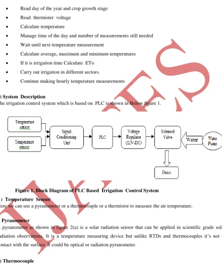
ii) System Description
The irrigation control system which is based on PLC is shown in Below figure 1.
Figure 1. Block Diagram of PLC Based Irrigation Control System
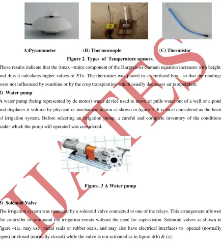
1) Temperature Sensor
Here we can use a pyranometer or a thermocouple or a thermistor to measure the air temperature.
i
) PyranometerA pyranometer as shown in figure 2(a) is a solar radiation sensor that can be applied in scientific grade solar radiation observations. It is a temperature measuring device but unlike RTDs and thermocouples it’s not in contact with the surface. It could be optical or radiation pyranometer.
ii) Thermocouple
A thermocouple as in figure 2(b) consists of two conductors of different materials (usually metal alloys) that produce a voltage in the vicinity of the point where the two conductors are in contact. Thermocouples are a widely used type of temperature senor for measurement and control and can also be used to convert a temperature gradient into electricity.
243 |
P a g e
A thermistor as in figure 2(c) is a specialized resistor, intentionally designed to be thermally sensitive and its primary characteristic is its ability to alter its electrical resistance in response to changes in case temperature. In this ,we use a 1k thermister with a 1% accuracy to measure the air temperature. It was connected in half duplex to an analog I/O port, using a 1k resistance.
A)Pyranometer (B) Thermocouple (C) Thermistor
Figure 2. Types of Temperature sensors.
These results indicate that the (tmax –tmin) component of the Hargreaves-Samani equation increases with height, and thus it calculates higher values of ETo. The thermister was placed in a ventilated box, so that the readings were not influenced by sunshine or by the crop transpiration which usually decreases air temperature.
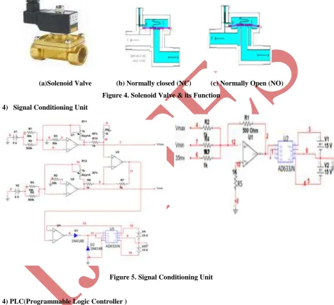
2) Water pump
A water pump (being represented by dc motor) was a device used to move or pulls water out of a well or a pond and displaces it volume by physical or mechanical action as shown in figure 3. It is most considered as the heart of irrigation system. Before selecting an irrigation pump, a careful and complete inventory of the conditions under which the pump will operated was considered.
Figure. 3 A Water pump
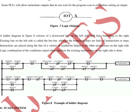
3) Solenoid Valve
The irrigation system was managed by a solenoid valve connected to one of the relays. This arrangement allowed the controller to command the irrigation events without the need for supervision. Solenoid valves as shown in figure 4(a), may use metal seals or rubber seals, and may also have electrical interfaces to opened (normally open) or closed (normally closed) while the valve is not activated as in figure 4(b) & (c).
Solenoid :-
Controls the flow of fluid through a pipe line by the compared action of the plunger along with the magnetic force created by the coil. The solenoid converts electrical energy into mechanical energy which, in turn, opens or closes the valve mechanically.
244 |
P a g e
The valve is controlled by an electric current through a solenoid. In the case of a two-port valve the flow is switched on or off; in the case of a three-port valve, the outflow is switched between the two outlet ports.Most solenoid valves operate on a digital principle. They therefore possess two distinct states, which are (1)when the coil is activated by an electrical current, and (2) when the valve is resting (without electricity). Valve functions are defined from the resting position. The direct acting or pilot operated solenoid valves may have two functions, Normally closed (NC) & Normally Open (NO) as shown in figure 4(b) & (c).
(a)Solenoid Valve (b) Normally closed (NC) (c) Normally Open (NO)
Figure 4. Solenoid Valve & its Function
4) Signal Conditioning Unit
Figure 5. Signal Conditioning Unit
4) PLC(Programmable Logic Controller )
245 |
P a g e
Table-1 General SpecificationsSpecification 1766 Controllers
Operating Temperature -20…60 °C (-4…140 °F)
Non operating Temperature
-40…85 °C (-40…185 °F)
Relative Humidity 5…95% non condensing
Vibration 3 g at 10... 500 Hz
Operating Shock 30 g
Non operating Shock Panel mount: 50 g, DIN mount: 40 g
Certifications⋆ UL Listed Industrial Control Equipment for use in Class 1, Division 2, Hazardous Locations, Groups A, B, C, D
5) Ladder Logic
5.1 Ladder Logic Inputs
PLC inputs are easily represented in ladder logic. There are three types of inputs ,first two are normally open and normally closed inputs, discussed previously. The IIT (Immediate Input) function allows inputs to be read after the input scan, while the ladder logic is being scanned. Normally open, an active input x will close the contact and allow power to flow and closed, power flows when the input x is not open as in below figure 6. IIT X immediate inputs will take current values, not those from the previous input scan.
Open Closed
Figure.6 Ladder Logic Inputs
5.2 Ladder Logic Outputs
In ladder logic there are multiple types of outputs, but these are not consistently available on all PLCs. The first is a normal output, when energized the output will turn on, and energize an output. The circle with a diagonal line through is a normally on output. When energized the output will turn off. When power is applied (on) the output x is activated for the left output, but turned off for the output on the right.
246 |
P a g e
When the L coil is energized, x will be toggled on, it will stay on until the U coil is energized. This is like a flip-flop and stays set even when the PLC is turned off.
Some PLCs will allow immediate outputs that do not wait for the program scan to end before setting an output.
Figure .7 Logic Outputs
A ladder diagram in figure 8 consists of a downward line on the left side with lines branching to the right. Existing line on the left side is called the bus bar, whereas the branching lines are lines of instructions or steps. Instructions are placed along the line of a variety of conditions linked to the other instructions on the right side. Logic combination of the conditions stated when and how the existing instructions on the right side is done.
Figure.8 Example of ladder diagram
6) SCADA SYSTEM
247 |
P a g e
• SCADA master/client :---Human Machine Interface(HMI). ---Alarm handling.
---Event and log monitoring. ---Special applications. ---ActiveX controls.
• SCADA slave/data server
--Real-time system manager. --Data processing applications. --Report generator.
--Alarm handling.
--Drivers and interfaces to control components . --Charting and trending.
--Typical SCADA system architecture --Spreadsheet.
--Data logging.
IV RESULT DISCUSSION
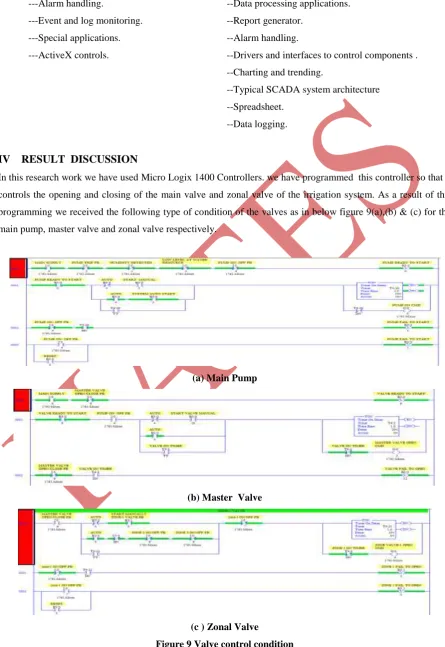
In this research work we have used Micro Logix 1400 Controllers. we have programmed this controller so that it controls the opening and closing of the main valve and zonal valve of the irrigation system. As a result of this programming we received the following type of condition of the valves as in below figure 9(a),(b) & (c) for the main pump, master valve and zonal valve respectively.
(a) Main Pump
(b) Master Valve
(c ) Zonal Valve
248 |
P a g e
We have also implement this irrigation system using SCADA system .This system clearly shows the condition of each valve and also all pipeline as shown in below figure 10.
Figure 10 System Using SCADA
V CONCLUSION
From this system we can clearly define the advantage of this irrigation system based on PLC that it is very flexible as only one single Programmable Logic Controller can easily run many machines. Correcting errors in PLC is extremely short and cost effective. Programmable Logic Control memory is getting bigger and bigger this means that we can generate more and more contacts, coils, timers, sequencers, counters and so on. We can have thousands of contact timers and counters in a single PLC. The program can be tested, validated and corrected saving very valuable time. Prices of Programmable Logic Controllers vary from few hundreds to few thousands. When running a PLC program a visual operation can be seen on the screen. Hence troubleshooting a circuit is really quick, easy and simple.
REFERENCES
[1] Baptista, J.M, Almeida M.C., Silva A.C.M., Ribeiro R., Fernando R.M., Serafim A., Alves I.,Cameira M.R. (2001) Programa Nacional para ouso eficiente da água, LNEC
[2] Allen, R.G.; Pereira, L.S.; Raes, D. and Smith,M. (1998). Crop evapotranspiration. Guidelines for computing crop water requirement. FAOIrrigation and Drainage Paper. 56, FAO, Rome
[3] Jensen, M. E. and Haise H.R. (1963) Estimating evapotranspiration from solar radiation. Journal of Irrigation and Drainage Division, Proc. Amer.Soc. Civil Eng. 89:15–41.
[4] Priestley, C. H. B. and Taylor R.J. (1972) On theassessment of the surface heat flux and evaporation using large-scale parameters. MonthlyWeather Review 100: 81–92
[5] Igbadun, H., H. Mahoo, A. Tarimo and B. Salim(2006) Performance of Two Temperature-Based Reference Evapotranspiration Models in the Mkoji Sub-Catchment in Tanzania Agricultural Engineering International: the CIGR Ejournal.Manuscript LW 05 008. Vol. VIII. March
249 |
P a g e
the estimation of reference evapotranspiration. Acta Hort. (ISHS) 449:113-118
[7] Wu I., (1997) A Simple Evapotranspiration Model for Hawaii: The Hargreaves Model, CTAHR Fact Sheet, Engineer’s Notebook no. 106
[8] Teixiera, J, Shahidian, S., Rolim, J., (2008) Regional analysis and calibration for the South of Portugal of a simple evapotranspiration model for use in an autonomous landscape irrigation controller, WSEAS transactions on Environment and Development, Issue 8, Volume 4, August
[9] shahidian, s.1 , serralheiro, r.p.1, teixeira, j.l.3, santos, f.l.1, oliveira, m.r.g.2,Costa, j.l.5, toureiro, c.1, haie, n.4, machado, r.m.2,drip irrigation using a plc based adaptive irrigation system, Wseas Transactions On Environment And Development, ISSN: 1790-5079, Issue 2, Volume 5, February 2009,pp 209-218. [10] Naregalkar Akshay, K. Uday Sravanth , Rahul Varanasi and J. Ankitha Reddy,”Real Time Automated Control of Industrial Processes with PLC –LABVIEW Communication,International Journal for Research in Science & Advanced Technologies ISSN: 2319-2690, Issue-1, Volume-1 ,035-038
[11] A.M Gaur1*, Rajesh Kumar 2, Amod Kumar3 and Dinesh Singh Rana4PLC Based Automatic Control of Rheometer International Journal of Control and Automation Vol. 3 No. 4, December, 2010,pp 11-20 [12] Zhang Feng ; Inst. of Inf. Technol. Yulin Univ.,Yulin, China ’Research on water-saving irrigation
automatic control system based on internet of things, International Conference on Electric Information & control Engineering(ICEICE) .2011 , pp 2541 – 2544
[13] Pranita A. Bhosale, Prof. V. V. Dixit,’ Water Saving-Irrigation Automatic Agricultural Controller [14] Automatic Irrigation Based on Soil Moisture for Vegetable Crops,’Rafael Muñoz-Carpena and Michael D. Dukes, IFAS, University of Florida, Gainesville, FL.