Modelling and controlof a Wind Turbine
using
Permanent Magnet Synchronous Generator
S.VIJAYALAKSHMI, Asst.Prof.EEE, SRM UNIVERSITY,
SAIKUMAR.S1, SARAVANAN.S2,R.V.SANDIP3, VIJAY SRIDHAR4 (B.Tech, EEE , SRM UNIVERSITY)
Abstract: This paper proposes a control strategy which analyses the configuration of a Wind Turbine generating system equipped with PMSG. There are different types of synchronous generators, but the PMSG is chosen. It offers better performance due to higher efficiency and less maintenance since it does not have rotor current and can be used without a gearbox, which also implies a reduction of the weight of the nacelle and a reduction of costs .Also WTGS consists of another three types: wind speed, wind turbine and drive train. These elements have been modelled and the equations that explain their behaviour have been introduced.The WTGS has been implemented in MATLAB/SIMULINK interface
.
Keywords: Wind Turbine, Modelling, PMSG, VSC
1. INTRODUCTION
The realization of a wind turbine as a source ofclean, non-polluting and renewable energy maydepend on the optimum design of the system andthe control strategies of the different possible parameters that can operate efficiently underextreme variations in wind conditions. Thegeneral goal of this paper is to optimize theelectromechanical energy conversion of the windturbines, developing suitable strategies of control[1].Both induction and synchronous generators can be used for wind turbine systems [2]. Mainly, three types of induction generators are used in wind power conversion systems: cage rotor, wound rotor with slip control and doubly fed induction rotors. The last one is the most utilized in wind speed generation because it provides a wide range of speed variation.
However, the variable-speed directly-driven multi-pole permanent magnet synchronous generator (PMSG) wind architecture is chosen for this purpose and it is going to be modelled: it offers better performance due to higher efficiency and less maintenance because it does not have rotor current. What is more, PMSG can be used without a gearbox, which implies a reduction of the weight of the nacelle and reduction of costs.
Optimum wind energy extraction is achieved by running the Wind Turbine Generator (WTG) invariable speed because of the higher energy gainand the reduced stresses. Using the PermanentMagnet Synchronous Generator (PMSG) the design can be even more simplified. However, therecent advancements in power electronics andcontrol strategies have made it possible to regulatethe voltage of the PMSG in many different ways.In the proposed system a VSI converter ispreferable [3,4].
Once themodel is made and tested sufficiently, thecontroller for an optimal command strategy isdeveloped so the wind turbine can perform alwaysin the maximum power point.
2. WIND ENERGY CONVERSION
The kinetic energy of the wind (air mass m,wind speed v) is given by the following equation:
1
2
With:(With S: Covered surface of the turbine and p: theair density) The wind power has the followingexpressions:
The mechanical power that the turbine extractsfrom the wind is inferior to . This is due tothe fact that the wind speed after the turbine isn’tzero (the air needs to be carried off after theturbine). So, the power coefficient of the turbine can be defined by:
;
1
The recuperated power is given by:
1
2
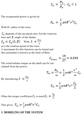
With R: radius of the rotor.depends of the tip speed ratio of the wind tur- bine and , angle of the blades.
,
With: is the rotation speed of the rotor.A maximum for this function can be found and this maximum is known as the limit of Betz:
16
27
0,593
The wind turbine torque on the shaft can be cal-culated from the power:
1
2
By introducing:1
2
Often the torque coefficient is used:
This gives:
3. MODELING OF THE SYSTEM
A wind turbine using Permanent MagnetSynchronous Generator is represented figure [1]:
Figure 1:Electrical scheme of a variable speed wind turbine equipped with a direct drive PMSG.
The generator is based on the park transformation
and the rectifier consists of 6 rectifiers which areplaced in bridge layout.
A. Wind Turbine
The Wind Turbine model is shown in thefollowing scheme:
Figure 2: Wind Turbine model
is calculated in the first subsystem using:
value is calculated in the next subsystem by using the following formula:
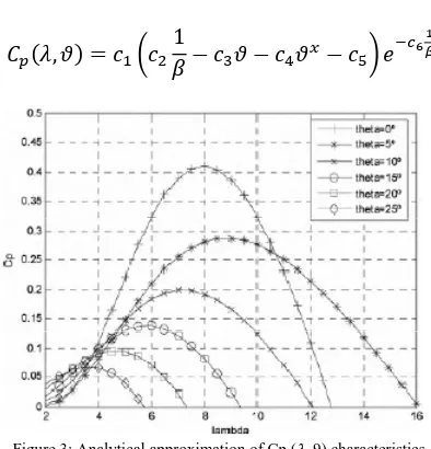
, 1
Figure 3: Analytical approximation of Cp ( .9) characteristics.
The rotational speed is calculated in the lastsubsystem by considering the followings:
J: Inertia moment of the turbine, axle and generator
F: Axle friction
: Electromagnetic torque
B. Generator Model
The PMSG has been considered as a system which makes possible to produce electricity from the mechanical energy obtained from the wind.
The PMSG can be modelled by using the simulation tool MATLAB Simulink. The equations used to model the PMSG are:
1
1
Where d and q refer to the physical quantities that have been transformed into the d-q synchronous rotating reference frame, Rs is the stator resistance, Ld, Lq are the inductances of the generator on the d and q axis is the electrical rotating speed of the generator.
Where p is the number of pole pairs of the generator. In order to complete the mathematic model of the PMSG the mechanical equation is needle and it is described by the following electromagnetic torque equation.
1.5
Lls
The following figure shows the equivalent circuit of the PMSGin thed-q synchronous rotating reference frame.
Figure4: Equivalent circuit of the PMSG in the syn-chronous frame.
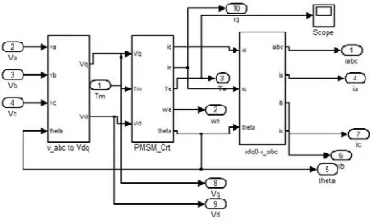
The model of the PMSG implemented in Simulink IS depicted in Fig5.
By analysing the power produced by the wind turbine atvarious wind and rotor speeds, as depicted in Fig.5, it can beappreciated that an optimum power coefficient constant Kp optexists. This coefficient show the generated power associatedwith the corresponding optimum rotor speed [6], [7], [8]. Kp optis calculated from individual wind turbine characteristics. Bymeasuring generated power, the corresponding optimum rotorspeed can be calculated and set as the reference speedaccording to [8],
where wr opt is the optimum rotor speed [rad/s] and Pgen is themeasured generated power [W].
This is the base of the well-known Maximum Power PointTracking (MPPT) [9], [10]: from the prior treatment of thewind turbine model it can be appreciated that in order to extractthe maximum amount of power from the incident wind, Cpshould be maintained at a maximum. In order to achieve this
objective, it can be appreciated from Fig. 3 that the speed ofthe generator rotor must be optimized according to instantaneous wind speed (this optimization is achieved byusing (10)).
Results and analysis
:For the variable speed operation of the WECS, a step signal is used in MATLAB, with a step size of 0.5 and the inputs before and after the step change to be 4 & 5.5 m per sec.
Figure 6: PMSG Integrated with wind turbine
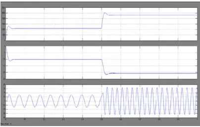
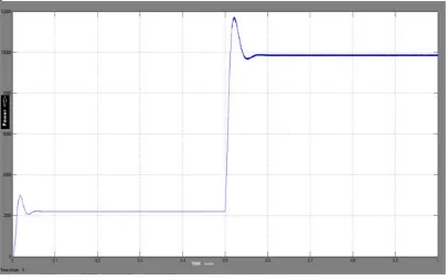
Figure7:Graph shows the variation of Speed, Torque and Voltage in any one phase with time for a stepped input variation.
Figure 8:Three phase voltage produced by PMSG
Figure 9: Variation of output power with time for a stepped input.
Figure 10: Output Voltage in Individual Phases
Figure 12: Inverter output after using smoothening filter
The graphs above show the variation of the respective parameters with respect to time. It is important to note that, the simulation time is 1 sec and a step input with a step time of 0.5 sec is used, that is, in all the graphs above there is a variation in the magnitude at the instant t=0.5 sec. This trend is seen in the graphs projecting the Generated three phase voltages, Generated Power, Electromagnetic Torque, Rectified Output Voltage and Inverter Output.
Figure 13: Torque vs. SpeedCharacteristics
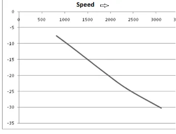
Figure 14:Wind Speed vs. other parameters
Conclusion:
The modelling of a variable speed wind turbine with a permanent magnet synchronous generator has been treated.
The model has been implemented in MATLAB/
Simulink inorder to validate it torque-speed and wind- speed characteristicshave been obtained.
The generator has been modelled in the d-q synchronousrotating reference frame, taking into account differentsimplifications. Moreover, the concept of the maximum powerpoint tracking has been presented in terms of the adjustment ofthe generator rotor speed according to instantaneous windspeed.
TABLE 1:
MOTOR PARAMETERS
TABLE II:
GENERATOR PARAMETERS
8. REFERENCES:
[1] H. STIESDAL; The wind turbine, components andoperation; 1999.
[2] J. G. Slootweg, S. W. H. de Haan, H. Polinder and W. L. Kling. "General Model for Representing Variable Speed Wind Turbines in
Power SystemDynamics Simulations". IEEE Transactions on Power Systems, vol. 18,no. 1,2003.
[3] A. Grauers, Efficiency of three wind energy generator systems, Department of Electric PowerEngineering, Chalmers University of
Technology,Sweden.
[4] M. Rasilia; Torque- and Speed Control of a Pitchregulated Wind Turbine; Chalmers University oftechnology; Göteborg, Sweden;
2003.
[5] Thiringer T., Linders J.; Control by variable rotorspeed of a fixed-pitch wind turbine operating in speedrange; Chalmers University of technology; Göteborg,Sweden; 2003.
[6] T. Ackermann. Wind Power in Power Systems. New York: John Wiley &Sons, 2005.
[7] S. Heier, Grid Integration of Wind Energy Conversion Systems. NewYork: John Wiley & Sons, 1998.
[8] Z. Lubosny. Wind Turbine Operation in Electric Power Systems. Berlin:Springer, 2003.
[9] G. Ramtharan and N. Jenkins. "Modelling and Control of SynchronousGenerators for Wide-Range Variable-speed Wind Turbines".
Wind Energy, Wiley Interscience, vol. 10, pp. 231-246, March 2007.
[10] M. Chinchilla, S. Arnaltes and 1. C. Burgos. "Control of PermanentMagnetGenerators Applied to Variable-Speed Wind-Energy