MODELLING AND ANALYSIS OF GPS
BASED TRAFFIC ALERT AND
COLLISION AVOIDANCE SYSTEM
(TCAS) USING ‘UPPAAL’
BAKARE K. AYENI
Nigerian College of Aviation Technology, Zaria Aeronautical Telecommunication Engineering School,
P.M.B. 1031, Zaria, Kaduna State, Nigeria. [email protected]
JUNAIDU B. SAHALU Department of Mathematics Ahmadu Bello University, Zaria
Kaduna State, Nigeria. [email protected]
Abstract
The Traffic alert and Collision Avoidance System (TCAS) is a collision avoidance system designed to reduce the incidence of mid-air collisions between aircrafts. TCAS monitors the airspace around an aircraft for other aircraft equipped with a corresponding active transponder and warns pilots of the presence of other transponder-equipped aircraft which may present a threat of mid-air collision (MAC).
In this paper, we present a design and analysis of GPS based TCAS to proffer solutions to some of the challenges like possibility of horizontal resolution, reversal logic and time based representation of traffic. Unlike existing TCAS systems, our model handles a situation where it has been shown that one of the two aircraft does not comply with the advisory given earlier by the TCAS and reversal logic is activated. Current version TCAS II can only support vertical separation advisories whereas more complex traffic conflict scenarios may be more easily and efficiently remedied by also making use of lateral resolution manoeuvres which is addressed in our proposed GPS based TCAS.
UPPAAL, a performance analysis tool based on timed automata, is used in the design and analysis of our proposed TCAS. Results of our analysis show that the time delay is minimal in modelling of a GPS based TCAS than transponder equipped TCAS. We note, however, that timed automata notation allows only one level of parallel composition and many numbers of states are covered in the TCAS modelling which prolongs early termination and reachability analysis of the timed systems as potential limitation of our proposed TCAS.
Keywords: TCAS , mid-air collisions, transponder, resolution, UPPAAL, Real- time embedded systems.
1 Introduction
Through this constant back-and-forth communication, the TCAS system builds a three dimensional map of aircraft in the airspace, incorporating their bearing, altitude and range. Then, by extrapolating current range and altitude difference to anticipate future values, it determines if a potential collision threat exists. Then it automatically negotiates mutual avoidance manoeuvre between the two or more conflicting aircrafts. Manoeuvres in current TCAS system are restricted to changes in altitude and modification of climb/sink rates, that is vertical plane only [6]. There may be instances where we can make use of lateral resolution manoeuvres which is addressed in this paper when we have complex traffic conflict scenarios between aircraft taking off or landing.
The first generation of collision avoidance technology is TCAS I. It is cheaper but less capable than the modern TCAS II system. TCAS I could generate collision warnings in the form of a "Traffic Advisory" (TA). The TA warns the pilot that another aircraft is in near vicinity, announcing "traffic, traffic", but unlike in TCAS II it could not offer any suggested remedy; it is up to the pilot to decide what to do, usually with the assistance of Air Traffic Controller [14]. When a threat has passed, the system announces "clear of conflict".
As of 2006, the only implementation that meets the TCAS II standards set by ICAO is Version 7.0 of TCAS II, produced by three avionics manufacturers: Rockwell Collins, Honeywell, and ACSS (Aviation Communication & Surveillance Systems; an L-3 Communications and Thales Avionics company). TCAS II offers all the benefits of TCAS I, but also offers the pilot direct "Resolution Advisory" (RA) to avoid danger [6]. The suggestive action may be "corrective", suggesting the pilot change vertical speed by announcing, "descend, descend", "climb, climb" or "Adjust Vertical Speed Adjust" (meaning reduce vertical speed) [10].
One of the related work is TCAS III developed by Honeywell which is expected to be the "next generation" of collision avoidance technology.
TCAS III like our proposed TCAS is expected to incorporate technical upgrades to the TCAS II system, allow reverse logic and increase total separation between aircraft both in horizontal and vertical aspects but the work was suspended due to limitations in the accuracy of the TCAS directional antennas [14,16].
In this paper, ‘UPPAAL’, a tool for performance analysis of Real-time embedded systems is used for modelling and analysis of our proposed GPS based TCAS with the following contributions :
• Introduction of horizontal resolution directives which are useful in a conflict between two aircraft close to the ground where there may be little, if any, vertical manoeuvring space possible
• Introduction of traffic situation given within a “time-based" representation because the existing TCAS is range-based that displays the traffic situation within a configurable ranges of miles/feet, however under certain condition there may be need for “time-based" representation.
• Introduction of Reversal logic where an RA issued by TCAS is reversed when it has been shown that after few seconds one of the two aircraft does not comply with the advisory given earlier by the TCAS. We note, however, that timed automata notation allows only one level of parallel composition and many numbers of states are covered in the TCAS modelling which prolongs early termination and reachability analysis of the timed systems as potential limitation of our proposed TCAS.
The rest of the paper is organised as follows: Introduction to UPPAAL use for the modelling is discussed in section 2. Section 2.1 focuses on informal system requirements. Section 2.2 is on formal system functionality. In section 3, proposed TCAS is formally modelled. Section 4 is on validation and verification of results. Future work and related work are discussed in sections 5 and 6 respectively. Section 7 concludes the work.
2 Introduction to UPPAAL
UPPAAL is a tool suite for symbolic model checking of real-time system developed jointly by Uppsala University, Sweden and Aalborg University, Denmark [4].
In this section, UPPAAL is briefly introduced; its uses and some applications are outlined.
UPPAAL is a network of timed automata. A timed automaton is a finite-state machine extended with clock variables. A finite state machine (FSM) or finite state automaton is a model of behavior composed of a finite number of states with transitions between those states and actions [8].
UPPAAL uses a dense-time model where a clock variable evaluates to a real number. All the clocks progress synchronously. In UPPAAL,a system is modelled as a network of several such timed automata in parallel. The model is further extended with bounded discrete variables that are part of the state [9]. These variables are used as in programming languages; they are read, written and are subject to common arithmetic operations.
UPPAAL is an integrated tool environment use for modelling, simulation and verification of real-time systems. It has been used to verify various benchmark examples and industrial applications, some of which are briefly discussed as follows:
Audio/Video control protocol which is highly dependent on real-time. The protocol was developed by Bang and Olufsen to transmit messages between audio/video components over a single bus, but it was known to be faulty and the error was not found using conventional testing methods. UPPAAL revealed the errors and suggested corrections [5].
In the work of [1], on Bounded Retransmission Protocol, UPPAAL showed that the correctness of the protocol is dependent on correctly chosen time-out values.
Magnus et. al., [7] applied UPPAAL in an industrial case-study to the design and analysis of an embedded system, gearbox controller prototype for vehicles by Mecel AB (a Swedish company developing control systems for vehicle industries). The correctness of the gear-box controller design was established by automatic verification of 46 properties derived from informal requirements specified by Mecel AB.
Also in the work of [2], TDMA (Time Division Multiple Access) Protocol Start-Up Mechanism, UPPAAL was used for formal verification of the start-up algorithm of a TDMA protocol. UPPAAL checked that an ensemble of three communicating stations becomes synchronized and operational within a bounded time.
Henrik et. al., [3] used UPPAAL to model Collision Avoidance Protocol implemented on top of an Ethernet-like medium such as the CSMA/CD (Carrier Sense Multiple Access/ Collision Detection) Protocol to ensure an upper bound on the communication delay between the network nodes.
We present the use of UPPAAL in the design and analysis of a GPS based TCAS. This, to our knowledge, is the first attempt to use UPPAAL in the design of a TCAS.
2.1 System Requirements
In this section, the informal requirements of TCAS are identified. The TCAS is capable of tracking up to a combined total of 30 intruders. Tracking is performed by repetitive TCAS interrogations.
Measurement of Intruder Parameter:
Upon confirmed transponder reception, the TCAS starts to interrogate the intruder. Its altitude is transmitted directly in the reply and this information is used to determine the relative altitude of the two aircrafts, by calculating the barometric altitude difference.
Range measurement:
The range is calculated by measuring the elapsed time between transmission of the interrogation signal and the return of the reply transmitted by the intruder. Aircrafts are detected from the range of at least 14 NM.
Principle of Computation
In TCAS, target aircrafts are categorized depending on specific criteria varying in function of altitude. TCAS essentially uses two types of information to perform this classification: The relative altitude between two aircrafts, known by the difference of their standard barometric altitudes and the distance or range separating them. Acquisition of these two parameters at regular intervals (tracking) enables their variations to be calculated, that is the altitude rate and range rate.
Assessment of the potential threat represented by an intruder depends on two criteria determined with respect to a point in the traffic area called Closet Point of approach (CPA). This is the point of minimum distance between the two aircraft, assuming that their trajectories do not deviate. The two criteria are vertical separation at CPA and time left before reaching CPA. The threat is evaluated by calculating the vertical separation between the two aircrafts at the closet point of approach.
Time to intercept (TAU)
There is an area defined as the TAU ( ) within the surveillance arc, which represents the minimum time the flight crew needs to discern a collision threat and take evasive action.
The TCAS does not need to locate the CPA in space, but rather it needs to know the time to intercept for two aircrafts. For example, if two aircrafts are approaching on the same axis on a collision course, this time is the ratio of distance between them to the sum of their speeds.
TCAS uses range and range rate measurement to compute this time, see Eq. (1) below: TAU ( ) = TAU (s) = ( ( )) (1)
2.2 Formal System Functionality
In this section, we formally describe the functionality of our proposed TCAS, abstract behaviour of the aircraft in the environment based on the desired informal specification requirements identified above and we finally model the system.
Performance requirements:
The performance requirements of our model are as follows: (i) The intruders should be detected within 60 seconds
(ii) The range of intruders should be acquired within 50 seconds
(iii) Traffic advisory should be given within 45 seconds if intruders range is within Closet Point of Approach (CPA)
(iv) Intruder should be declared as a threat within 35 seconds if intruders range is considered dangerous at the Closet Point of Approach (CPA)
(v) Preventive resolution advisory should be given within 30 seconds if intruders range is considered dangerous at the Closet Point of Approach (CPA). Here the vertical separation is less than upper preventive advisory threshold but greater than upper corrective advisory threshold.
(vi) Corrective resolution advisory should be given within 30 seconds if intruders range is considered dangerous at the Closet Point of Approach (CPA). In this case the vertical separation is lower than the upper corrective advisory threshold.
(vii) TCAS should be able to indicate clear of traffic or traffic not clear within 5 seconds if conflict is resolved or otherwise.
(viii) If conflict is not resolved within 5 seconds, TCAS should be able to perform reversal logic by carrying out the following steps
(ix) TCAS should be able to acquire the new range for the intruders within 5 seconds. (x) TCAS should do step (f) and (g).
Predictability:
The predictability requirements are to ensure strict synchronisation and control between aircrafts equipped with TCAS.
(i) There should be no deadlocks in the system.
(ii) TCAS of all the aircrafts during tracking should be functional Error detection :
The TCAS detects and indicates error when :
(i) Intruder is detected but range and bearing could not be determined (ii) Appropriate advisory is not given timely
(iii) Sensitivity level prevents intruder to comply with the advisory
(iv) Collision threat is still detected after advisory if one of the intruders does not comply with TCAS.
Existing TCAS :
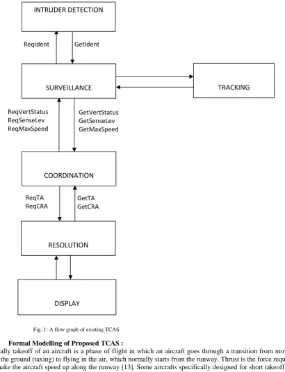
In the existing TCAS, see fig.1, nodes in the flow graph of the model represent automata and edges represent synchronisation channels or shared variables. The components have two channels associated with each service, one for service request and one to respond when the service has been performed.
The existing TCAS is limited to supporting only vertical separation advisories but more complex traffic conflict scenarios may however be more easily and efficiently remedied by also making use of lateral resolution manoeuvres.
TCAS equipment today is often primarily range-based, as such it only displays the traffic situation within a configurable range of miles/feet, however under certain circumstances a "time-based" representation (that is, within the next certain minutes or seconds) might be more intuitive.
Fig. 1: A flow graph of existing TCAS
3 Formal Modelling of Proposed TCAS :
Generally takeoff of an aircraft is a phase of flight in which an aircraft goes through a transition from moving along the ground (taxing) to flying in the air, which normally starts from the runway. Thrust is the force required that make the aircraft speed up along the runway [13]. Some aircrafts specifically designed for short takeoff and landing can take off at speeds below 40 knots (74 km/h), and can even become airborne from a standing start when pointed into a sufficiently strong wind [15].
In the existing TCAS, if an aircraft is taking off and another one is approaching to land and is below the altitude of 1450ft on the same runway, although the TCAS on these two aircrafts can detect each other but vertical resolution cannot be issued for the two aircrafts, because naturally, the aircraft that is approaching to land has lost power during descent, the spoilers increase the drag force and slow down the aircraft. Issuing climb command of vertical resolution to the pilot at this moment could be hazardous to the aircraft because at that stage full power cannot be gained instantaneously, in the attempt the aircraft could stall.
For the aircraft that is taking off, if it is estimated to be within 400 ft closer to the ground and is climbing at say 150 or 450, it will be difficult for such an aircraft to suddenly climb at 900 or higher or descend immediately to 2700 in compliance with vertical resolution, the aircraft may overshoot the runway or crash land. As a result of this, lateral resolution is the only way out, where aircraft can be advised to yaw to the left or to the right while landing or taking off as the case may be.
SURVEILLANCE
COORDINATION
RESOLUTION
TRACKING
DISPLAY
ReqIdent GetIdent
ReqVertStatus ReqSenseLev ReqMaxSpeed
GetVertStatus GetSenseLev GetMaxSpeed
ReqTA ReqCRA
GetTA GetCRA
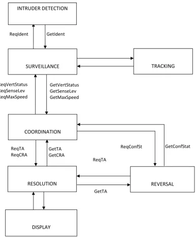
In our proposed TCAS, we assumed that the TCAS is equipped with GPS and the pilots of the two aircrafts will obey TCAS advisories. TCAS components are designed to be functionally correct in the given environment. TCAS modelling in fig.1 of the existing TCAS is extended. The automata Surveillance and Coordination of the existing TCAS are modified to include lateral resolution manoeuvres. Reversal automaton is also added to our proposed modelling to enabling reverse logic. See fig.2 for the changes.
TCAS components are modelled using UPPAAL by the automata SURVEILLANCE, COORDINATION, RESOLUTION and DISPLAY. The environment is modelled by automata INTRUDER DETECTION, and TRACKING.
Fig. 2: A flow graph of New TCAS
Intruder Detection:
In automaton INTRUDER DETECTION (fig.3) aircraft equipped with TCAS receives squitter messages transmitted by the intruder. Automaton continues broadcast at location activeBrodcast if x>=55 and aircraft is actually detected at location ACdetectd if x<=50. An urgent location Identf is entered if x<=45 and Ident! channnel from Ident! location synchroniseswith Ident? of SURVEILLANCE automaton.
ReqConfSt GetConfStat
REVERSAL SURVEILLANCE
COORDINATION
RESOLUTION
TRACKING
DISPLAY
ReqIdent GetIdent
ReqVertStatus ReqSenseLev ReqMaxSpeed
GetVertStatus GetSenseLev GetMaxSpeed
ReqTA ReqCRA
GetTA GetCRA
GetTA ReqTA
Fig. 3 : The INTRUDER DETECTION Automaton
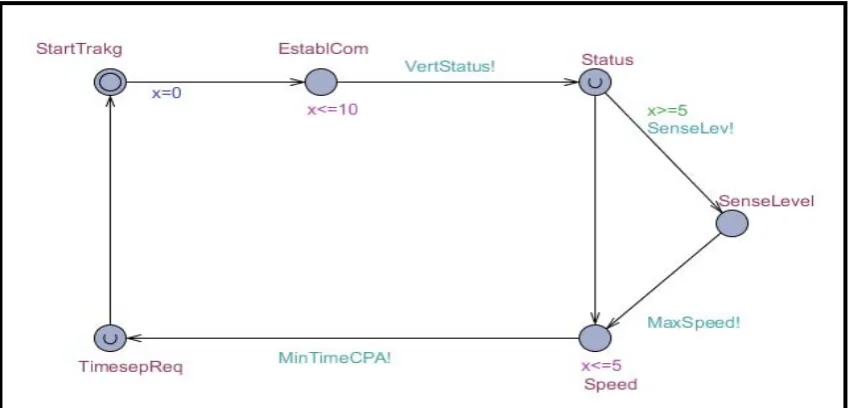
Tracking:
Tracking is performed by repetitive TCAS interrogations, in the aircraft equipped with transponders, the TCAS is active and transmits pulses.
The aircraft under SURVEILLANCE automaton is tracked within 5 seconds and gives GetVertStatus, GetSenseLev and GetMaxSpeed services output (see fig.4). After an aircraft is identified, TCAS establishes communication with the intruder and a delay condition for a maximum of 10 clock constraints before VertStatus! channel is enabled and the transition enters an urgent location Status with a guard of x>=5 allowed. Transition is delayed for a maximum of 5 seconds in location Speed before it enters TimesepReq location and back to StartTrakg location of automaton TRACKING.
Fig. 4: The TRACKING Automaton
Surveillance:
Transition is from start to initialise, IdentAcqd and status location after the corresponding guard or invariant constraints are satisfied. The status determines if the location is at ACground or ACairborne based on the clock constraints.
If the location is at ACground the transition is taken to Aclevel location instead of start location as modelled in the existing TCAS where there is no TCAS resolution between aircraft on the ground and airborne. The transition then move to ACAlt, CurtRange and finally to start of the automaton.
Fig. 5 : The new SURVEILLANCE Automaton
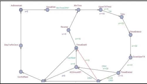
Coordination:
In the COORDINATION automata, the transition is through the following locations; AcBroadcast, ThreatDetc, UpperTAThrsd, TAdv, ThreatDetecd, ExcedUperTAThrsd, ThreatDeclad, ACAirbornST, to ACGroundST or ThreatDetAf to Reverse, MinTime or CPA to ConflctResd, DispTrafficClerd and finally to AcBroadcast after satisfying the guard or invariant constraints on the edges or locations.
TCAS checks the vertical status of the aircraft, its sensitivity level and maximum speed of the two aircraft before giving any advisory procedure. Preventive Traffic Advisory is given by TCAS if the aircraft is at the threshold in UpperTAThrsd location.
Like in the coordination automata of the existing TCAS, a threat is declared within 33 seconds if traffic advisory given earlier could not resolve the sensed head-on collision. Transition moves to ExcedUperTAThrsd location, if threat is detected again, within a delay of 5 seconds in location ThreatDeclad, resolution phase is entered where vertical Corrective Resolution Advisories (CRA) is given within 25 seconds if the aircraft that is air borne is very close to location CPA (see fig 6).
Fig. 6 : The new COORDINATION Automaton
Resolution:
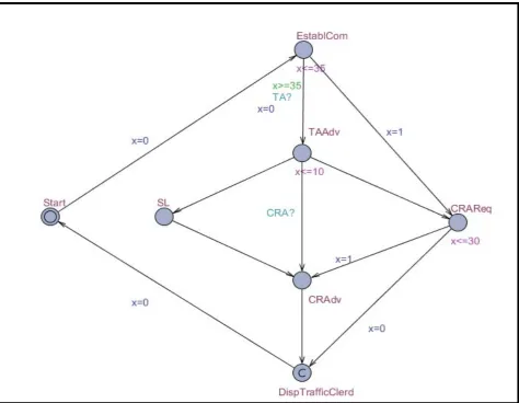
When the target intruder is relatively near but does not represent an immediate threat, in that case the target is between the upper traffic advisory threshold and upper preventive traffic advisory threshold, the TCAS issues a preventive traffic advisory, (see fig.7) the display will indicate traffic. The range and relative bearing of the aircraft is known to the pilot as well as time TAU before CPA value. When the system is updated, now depending on the current trajectory, the target intruder may conserve this status and move away or it may become a collision threat, in that case the target is between the upper corrective advisory threshold and CPA. As a result of this, collision is possible, avoidance manoeuvre are issued immediately to the pilot via a corrective resolution advisory (fig.8).
Fig. 7: TCAS Corrective / Preventive Advisory Threshold
The transition in this automata is from startwithout any update to EstablCom location, transition is enabled after satisfying the guard constraint to location TAAdv or CRAReq, the edges TA? and CRA? of TAAdv and
CPA
UPPER TA THRESHOLD
UPPER PREVENTIVE ADVISORY THRESHOLD
UPPER CORRECTIVE ADVISORY THRESHOLD
LOWER CORRECTIVE ADVISORY THRESHOLD
LOWER PREVENTIVE ADVISORY THRESHOLD
CRAdv synchronise with that of automaton COORDINATION. If corrective resolution is successful, the urgent location DispTrafficClerd is entered to display the resolution.
Fig. 8 : The RESOLUTION Automaton
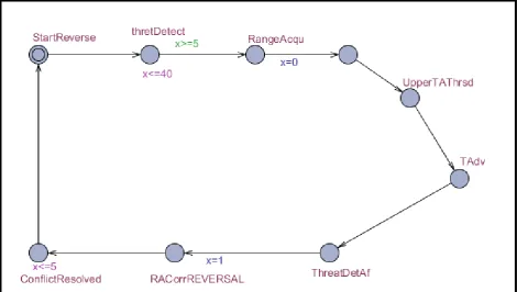
Reversal:
In REVERSAL automaton, the system checks to confirm Corrective Resolution Advisory (CRA) compliance by the targets every 5 seconds (fig.9). When it is detected after this time that an aircraft is not responding correctly to an RA, the process enters urgent location and reversal phase is triggered automatically.
The vertical separation at the closest point of approach based on current vertical speeds of the aircraft are probably going to be closer than a predefined upper threshold of TA, then the CTA is issued based on the current acquired range.
Fig. 9 : The new REVERSAL Automaton
4 Validation and Verification of Results
In this section, we show the formal requirements given in section 2.3 and ascertain their correctness using the symbolic model-checker of UPPAAL to check the state and path formulae for their rechability, safety and liveness. In these properties, we check whether a given state formula, , possibly can be satisfied by any reachable state that is, given a path starting at the initial state, we find out whether such is eventually satisfied along that path and safely within a given time bound.
The first performance requirement is that the intruder must detect and identify itself within 60 seconds. We show that it requires the location ACDetect to be reached in automaton INTRUDER DETECTION if clock <=50 and urgent location Identf is entered if the time is less than or equal 45 seconds. Also, error should occur if the intruder fails to identify itself.
We verified that after the intruder is identified, automaton SURVEILLANCE initialised interrogation to get required parameters. Transition is not delayed at location status to know whether the intruder is on the ground or airborne. We verified that if location status of automaton SURVEILLANCE is reached, invariably location speed will be reached. Property 21 requires that preventive traffic advisory should be given within 35 seconds if the detected intruder wants to exceed threshold. The corrective advisory both in vertical or horizontal resolution is given to the target aircraft within 25 and 30 seconds as soon as the process enters ACAirbornST and ACGroundST state in properties 22 and 23 respectively. (See appendix A for the list of some of the verified properties).
In properties 30 and 31 we confirm that Conflict Status of the resolution given to the intruder is checked every 5 seconds to ensure compliance. If target aircraft failed to implement recommended manoeuvre, the corrective resolution is reversed within 10 seconds. The time bound given for this operation is between 5 and 10 seconds. We verified in property (44) that invariantly there is no deadlock in the system. See appendix A for the list of some of the verified properties.
We have been able to verify over fourty various properties of the system using UPPAAL installed on a 1.795 GHz Pentium IV PC equipped with 1GB of RAM. The verification of all the properties consumed 88.37 seconds.
For instance, the information below was displayed :
$GPGGA,002253.000,3342.6618,N,11751.3858,W,1,10,1.2,27.0,M,-34.2,M,,0000*5E
Where the desired trajectory data are 002253.000 which is the time, 3342.6618 is the latitude to the north N indicator and the 11751.3858 is the longitude to the west W indicator.
5 Future Work
Future extensions of this work are possible. For instance, there is a need to develop techniques that combine symbolic representation of timing information with symbolic representation of control locations.
Another possible future work is to identify a minimal set of covering states that ensures termination and reachability analysis of timed systems.
Also this work can be extended to allow possibility of integration of TCAS and GPWS (Ground Proximity Warning System).
6 Related Work
One of the related work is TCAS III developed by Honeywell which is expected to be the "next generation" of collision avoidance technology.
TCAS III like our proposed TCAS is expected to incorporate technical upgrades to the TCAS II system, allow reverse logic and increase total separation between aircraft both in horizontal and vertical aspects but the work was suspended [14].
International Civil Aviation Organisation (ICAO) Standard and Recommended Practices (SARPs) for TCAS III have not been developed [11] before the TCAS III was judged by the industry to be unfeasible due to limitations in the accuracy of the TCAS directional antennas. The directional antennas were judged not to be accurate enough to generate an accurate horizontal-plane position, and thus an accurate horizontal resolution. As a result, TCAS III concept was later evolved and replaced by TCAS IV to prevent confusion between technologies [12]. TCAS IV is expected to use additional information that encoded the target aircraft position in the transponder reply to generate a horizontal resolution to an RA[16].
In addition to TCAS III or TCAS IV capability, our proposed TCAS introduces traffic situation given within a “time-based" representation.
7 Conclusion
We modelled GPS based TCAS and verified over fourty various properties of the system using UPPAAL, a Timed Automata based performance analysis method installed on a 1.795 GHz Pentium IV PC equipped with 1GB of RAM. The verification of all the properties consumed 88.37 seconds.
In our model, we found out that the time delay in a GPS based TCAS is minimal and the traffic resolution could be issued on a time bases (that is, resolution given within a certain period of time) than TCAS equipped only with Transponder because the information about current time, date,
position and many more are displayed continuously every second from GPS satellite. Also we verified that lateral resolution manoeuvres could be issued to TCAS equipped aircrafts approaching to land and the other one taking off.
We verified that our system is dynamic because with the feedback from ‘ThreatDetAf’ state which depends on other states, Reversal logic is automatically enabled in a situation where it is obvious that one of the two aircrafts failed to comply with the earlier resolution advisory given by TCAS.
Failure of many real-time computer systems may endanger human life or may cause substantial loss in economic values. Implementation of GPS based TCAS will improve complex traffic conflict scenarios more easily, safely and efficiently especially lateral resolution manoeuvres where vertical resolution is not practicable. Nonetheless, in the modelling of our proposed TCAS using UPPAAL, we identified some limitation; Time automata notation allows only one level of parallel composition, that is individual automaton in a system cannot themselves contain parallel compositions. This leaves a question mark over the scalability of the notation. Also many number of states are covered which prolong early termination and reachability analysis of the timed systems. There is a need to identify minimal set of covering states to ensure early termination.
8 Acknowledgement
9 References
[1] Argenio P.R. D’, Katoen J. P., Ruys T.C. and Tretmans J, The bounded retransmission protocol must be on time. In Proc. of the 3rd Workshop on Tools and Algorithms for the Construction and Analysis of Systems, number 1217 in Lecture Notes in Computer Science, Springer–Verlag, 1997, pp 416 – 431
[2] Henrik Lonn and Paul Pettersson , Formal Verification of a TDMA Protocol Startup Mechanism. In Proc. of the Pacific Rim Int. Symp. on Fault Tolerant Systems, (1997) 235-242.
[3] Henrik E. Jensen, Kim G. Larsen, and Arne Skou, Modelling and Analysis of a Collision Avoidance Protocol Using SPIN and UPPAAL. In Proc. of 2nd Int. Workshop on the SPIN Verification System, (1996) 1–20.
[4] Larsen K.G., PetterssonP. andYiW., UPPAALin a nutshell, International Journal on Software Tools for Technology Transfer - STTT, vol. 1, no. 1- 2, (1997), 134-153.
[5] Klaus Havelund, Arne Skou, Kim G. Larsen, and Kristian Lund, Formal Modelling and Analysis of an Audio/Video Protocol: An Industrial Case Study Using UPPAAL. In Proc. of the 18th IEEE Real-Time Systems Symposium. IEEE Computer Society Press (1997).
[6] Lufthansa Resource Technical Training Manual, Part 66, 2005, pp 328 - 370.
[7] Magnus Lindahl, Paul Pettersson, and Wang Yi, Formal Design and Analysis of a Gear-Box Controller. In Proc. of the 4th Workshop on Tools and Algorithms for the Construction and Analysis of Systems, number 1384 in Lecture Notes in Computer Science, Springer–Verlag, 1998 pp 281–297.
[8] Rajeev Alur and David L. Dill, A theory of timed automata. Theoretical Computer Science, 126(2) (1994), 183-235. [9] Yovine S., Model checking timed automata in Embedded Systems, LNCS 1494, 1998.
[10] http://eurocontrol.int/TCAS II version 7.1 Retrieved 2010-10-25
[11] www.skybrary.aero/index.php/ACAS Retrieved 2011 - 07- 02
[12] http://yarchive.net/air/airliners/tcas.html Retrieved 2011 - 07- 02
[13] www.fi.edu/flights/own2/forces.html Retrieved 2010-12-25 [14] www.en.wikipedia.org/wiki/TCAS. Retrieved 2010-12-25
[15] www.free-online-private-pilot-ground-school.com/copyright.html Retrieved 2010-12-25 [16] www.en.wikipedia.org/wiki/TCAS. Retrieved 2011 - 07- 02
Appendix A
Verified Properties
E<>IntrDetect.ACdetectd (1)
E<>IntrDetect .Identf (2)
E[ ] (IntrDetect.Identf imply x<=60) (3)
E<> (IntrDetect.Identf imply x<=45 and x<=50) (4) E<> IntrDetect.StartInterrg imply IntrDetect.Identf (5) E<>Surveillance.IdentAcqd imply x<=5 (6)
E<>Surveillance.Status (7)
E<>(Surveillance.Status imply Surveillance.ACground) (8) E<>(Surveillance.Status imply Surveillance.ACairborne) (9) E<>(Surveillance.Status imply Surveillance.Speed) (10) E<> Surveillance.Status imply Surveillance.Aclevel (11) E<> Surveillance.Status imply Tracking.Status (12)
A[] Tracking.SenseLevel imply (x<=5) (13)
E<> Tracking.SenseLevel imply Surveillance.ACairborne (14) E<> Tracking.SenseLevel imply Surveillance.ACground (15) E<> Tracking.Speed imply Surveillance.Speed (16)
E<> Tracking.Speed imply x<=5 (17)
E<> Surveillance.Initialise imply Tracking.EstablCom (18) A[] Coordination.ACAirbornST imply (x<=5 and x>=25) (19) E<> Coordination.ACGroundST imply (x<=5 or x<=30) (20) E<> Coordination. TAdv imply x<=35 (21) A[] Coordination. ACAirbornST imply (x<=25) (22) A[] Coordination.ACGroundST imply (x<=30) (23) E<> Coordination. TAdv imply Coordination.ThreatDetecd (24) E<>Coordination. ExcedUperTAThrsd imply Coordination. ThreatDeclad (25) E<>Coordination.ACAirbornST imply Coordination.ACGroundST (26) E<> Coordination.ThreatDetecd imply (Coordination.ACAirbornST and
E<>Coordination.ACGroundST imply Coordination.ThreatDetAf (29) A[] Coordination.ThreatDetAf imply (x<=5 ) (30)
A[]Coordination.Reverse imply (x<=10) (31)
E<>Coordination.ThreatDetAf imply Coordination.Reverse (32) E<>Coordination.MinTime imply (Coordination.ThreatDetc or
Coordination.Reverse) (33)
A[] Coordination.Reverse imply (x<=5 and x>=10) (34) E<>Coordination.CPA imply (Coordination.ACAirbornST or
Coordination.ACGroundST or Coordination.ThreatDetAf) (35) E<>Coordination.ConflctResd imply Coordination.CPA (36) E<> Resolution.EstablCom imply Resolution.TAAdv (37) E<>Resolution.TAAdv imply Resolution.CRAdv (38) E<> Resolution.EstablCom imply Resolution.CRAReq (39) E<>Resolution.CRAdv imply Resolution.DispTrafficClerd (40) E<> Resolution.CRAReq imply Resolution.CRAdv (41) A<>Resolution.TAAdv imply Resolution.CRAdv (42) E<>Reversal.RACorrREVERSAL imply Reversal.ConflictResolved (43)