City, University of London Institutional Repository
Citation
:
Vidal Roncero, A. ORCID: 0000-0001-8177-518X, Koukouvinis, P. ORCID:
0000-0002-3945-3707 and Gavaises, M. ORCID: 0000-0003-0874-8534 (2019). Effect of
Diesel injection pressures up to 450MPa on in-nozzle flow using realistic multicomponent
surrogates. Paper presented at the ILASS 2019 - 29th European Conference on Liquid
Atomization and Spray Systems, 2 - 4 September 2019, Paris, France.
This is the published version of the paper.
This version of the publication may differ from the final published
version.
Permanent repository link:
http://openaccess.city.ac.uk/id/eprint/22849/
Link to published version
:
Copyright and reuse:
City Research Online aims to make research
outputs of City, University of London available to a wider audience.
Copyright and Moral Rights remain with the author(s) and/or copyright
holders. URLs from City Research Online may be freely distributed and
linked to.
City Research Online:
http://openaccess.city.ac.uk/
[email protected]
Effect of Diesel Injection Pressures up to 450MPa on In-nozzle Flow
Using Realistic Multicomponent Surrogates
Alvaro Vidal
∗, Phoevos Koukouvinis
1, Manolis Gavaises
11
City University London – Northampton Square, London EC1V 0HB, United Kingdom
*Corresponding author:[email protected]
Abstract
Investigations with 300MPa injection pressures show significant soot reduction, but the effect of such extreme pressures on the in-nozzle flow has not been closely examined. The study of the in-nozzle flow is important because it dominates primary break-up characteristics and therefore the combustion efficiency. Moreover, the characteristic pressure drops in Diesel injectors may cause the fuel to cavitate, which leads to enhancements in the nozzle outlet velocity, the spray cone angle and the fuel atomisation. In this work, the fuel property database is modelled using the molecular-based PC-SAFT EoS with an eight-components surrogate based on a grade no. 2 Diesel emissions-certification fuel. The composition for the surrogate is (in mole fration): 2.7% hexadecane, 20.2% n-octadecane, 29.2% heptamethylnonane, 5.1% n-butylcyclohexane, 5.5% trans-decalin, 7.5% trimethylbenzene and 15.4% tetralin. Then, this surrogate is utilised in simulations for a common rail 5-hole tip injector tapered nozzle. The needle is assumed to be still at a lift of 100µm, which is representative of the lift reached during pilot injection. The injector operating pressures start from 180MPa and reach 450MPa. The collector back pressure is 5MPa. The density of the bulk fluid is assumed to vary according to a barotropic-like scheme, following an isentropic expansion. Results show an increase in the mass flow rate, following the square root of the pressure difference law and also in the outlet velocity, both as expected. Surprisingly, the cavitation is significantly reduced as the injection pressure increases. A focused study on this particular phenomenon shows a significant decrease in the Reynolds number in the sac, therefore the flow is found to be more stable and the pressure drop along the nozzle is smaller. The reason for the lower Reynolds number is found on the heavy nature of Diesel fuels. While the sac average velocity increases 15% between an injection pressure of 180MPa and 450MPa, the kinematic viscosity increases close to a 70%.
Keywords
cavitation, multicomponent, PC, SAFT, diesel
Introduction
Research on diesel injector systems for improving the combustion efficiency and meeting emission regulations from all types of diesel powertrains is a pressing environmental issue. Several strategies have been sought to study and decrease soot emissions, such as the use of diesel surrogates [1], additives in diesel and bio-diesel blends [2], the use of multiple injections per power cycle [3] and the increase in injection pressure [4]. Modern diesel engines operate with upstream pressures around 200MPa, although the current trend is to increase them up to 300MPa, as included in the forthcoming EU emission regulations. However, due to the micrometer scales of injectors, high injection pressures will irremediably cause very high fuel velocities which, added to the sharp geometric changes in the injector passages, lead to significant pressure gradients and local depressurization. Then, if the pressure decreases beyond the saturation point, the fuel may vaporise in a phenomenon known as cavitation, which in turn is related to injector erosion and under-performance [5].
The main observed effect of cavitation is on liquid jet atomisation [6, 7, 8, 9]. Faeth et al [10] found that primary break-up characteristics, those of the fuel jet near to the nozzle exit, were dominated by the characteristics of the in-nozzle flow, primarily by the disturbances found therein. From there, several studies followed. It has been observed that cavitation enhances atomisation performance [11], increases the spray cone angle [12], and it is related to mass flux choke due to obstaculisation of the free flow, enhancing then the nozzle outlet velocity [13].
The occurrence of cavitation is influenced by several factors. It is commonly known that tapered nozzles reduce the appearance of cavitation [14]. Although the usual place for cavitation to appear is close to the upper part of the injector hole, a low needle lift may flip it to the bottom part [15]. Moreover, it was observed for circular sharp edged orifices that cavitation reduces the mixing uniformity within the orifice[16].
ILASS – Europe 2019, 2-4 Sep. 2019, Paris, France
Mw Tb z m σ /k
Compound Name [g/mol] [K] [% mol] [-] [Å] [K]
n-octadecane 254.5 590.0 20.2 7.438 3.948 254.90
n-hexadecane 226.4 560.0 2.7 6.669 3.944 253.59
heptamethylnonane 226.4 520.0 29.2 5.603 4.164 266.46
1-methylnaphthalene 142.2 518.0 14.4 3.422 3.901 337.14
n-butylcyclohexane 140.3 456.2 5.1 3.682 4.036 282.41
trans-decalin 138.2 460.5 5.5 3.291 4.067 307.98
tetralin 132.2 480.9 15.4 3.088 3.996 337.46
[image:3.595.76.520.70.179.2]1,2,4-trimethylbenzene 120.2 442.6 7.5 3.610 3.749 284.25
Table 1.Molar composition for the diesel surogate [34] modelled here. Boiling points at 0.1 MPa taken from the literature.
Recently, more accurate and computationally expensive models have been developed accounting for realistic in-jector characteristics, most of them based on large eddy simulations (LES), as it was found that LES is capable of reproducing the turbulent structures in diesel nozzles [23]. Using this turbulence model, computational studies showed that cavitation enhances turbulence since the highest values of vorticity were found at the liquid-vapor inter-phase [24]. Nevertheless, the state-of-the-art on cavitation modelling is the simulation of injections accounting for realistic moving needles. Both cavitation and the lateral and radial movements of the needle have been successfully calculated depending on the liquid compressibility [25]. On the contrary, realistic needle moving have been imposed to study the effect of cavitation on primary atomisation [26] and the relation of cavitation and erosion [27].
In most of the simulations described above, the properties of the fluid in liquid the state are assumed to follow a barotropic evolution, i.e. pressure and density are one to one related, if not assumed constant. For the vapor, however, the usual assumption is for constant properties. In the former case, the barotropic equation is usually derived following Kolev’s diesel properties collection [28] or single component approximations using the NIST Ref-prop [29] database. However, the use of constant Ref-properties may lead to large deviations in discharge coefficient and fuel heating predictions, particularly in cases of high pressure injections [30]. On the other hand, composition effects in diesel fuel are related to changes in the cavitation cloud size [31], the spray atomisation [32], and spray tip penetration [33].
The aim of the current work is to simulate the in-nozzle flow during a diesel injection at injection pressures up to 450MPa using a realistic multicomponent diesel surrogates, studying the differences from their outcomes. The surrogate is a mixture of eight components based in the composition of a grade no. 2-D S15 diesel emissions-certification fuel from Chevron-Phillips Chemical Co. [34]. The surrogate was tested to mimic the characteristic composition, ignition quality, volatility, density, and other properties from the objective diesel fuel and has been already modelled using the molecular-based PC-SAFT equation of state [35]. The surrogate composition is listed in Table 1.
(a) Geometry and boundary conditions (BC)
(b) Detail of the mesh
Figure 1.Simulated geometry, one fifth of the total structure.
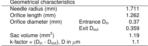
[image:3.595.116.487.476.702.2]Geometrical characteristics
Needle radius (mm) 1.711
Orifice length (mm) 1.262
Orifice diameter (mm) Entrance Din 0.37 Exit Dout 0.359
Sac volume (mm3) 1.19
[image:4.595.173.420.70.147.2]k-factor = (Din- Dout), D inµm 1.1 Table 2.Dimension of the injector used for the simulations on this work.
Numerical Method
Injector geometry and operating conditions
The examined injector geometry was based on a common rail 5-hole tip injector with tapered nozzle. The most important dimensions for this injector is shown in Table 2. As focus is given here on the effect of fuel properties, complications arising from the needle valve motion have been ignored. Although the simulation is transient, the needle was assumed to be still at its full lift of 310µm, reached during the majority of the main injection. Incorporation of needle motion would obviously produce a different result, although the differences at these lifts may not excuse the increase in computational effort [36]. The simulated geometry consisted on 1/5 of the full injector geometry, as shown in Figure 1a, imposing periodic boundary conditions on the symmetry planes. Moreover, constant pressure boundary conditions of 180, 250, 350 and 450MPa at the inlet and 5MPa at the outlet have been assumed. It must be noted that there is a hemispherical volume attached to the nozzle exit; this volume is added in order to be able to capture the complete cavitation cloud, which may extend out of the orifice.
Regarding the computational mesh, two topologies have been used, as shown in Figure 1b. Before the orifice entrance, in the sac volume, there is an unstructured tetrahedral mesh. For the rest of the domain, a hexahedral block-structured mesh is used. The total number of cells in the numerical mesh was∼1.4M. Regarding the use of turbulence model, studies have shown that RANS models suffer from significant pitfalls when resolving the cav-itation cloud [37], while the more accurate Large Eddy Simulations (LES) are able to resolve the highly transient phenomena typical of a fuel injector. Therefore, the Wall Adapting Local Eddy-viscosity (WALE) LES is used in this work.
CFD model
The in-house density-based CFD code used in this work solves a laminar, compressible and viscous Navier-Stokes system in the open-access OpenFOAM platform. This solved system consist of the continuity equation:
∂ρ
∂t +∇ ·(ρu) = 0 (1)
and the momentum equation:
∂(ρu)
∂t +∇ ·(ρu⊗u) =−∇p+∇ ·τ (2)
whereρis the density,tis time,uis the velocity field,pis the pressure andτ is the stress tensor, related to the viscosity among other properties.
The energy equation is omitted here. The reason for omitting heat effect was the assumption of adiabatic injection, as its characteristic time-scales are small enough for heat to be unlikely exchanged.
Two phase flows are characterized, among others, by large variations in speed of sound. While the speed of sound in the liquid phase is in the order ofO(103)m/sand that of gas isO(102)m/s, in the liquid-vapour it sanks down to O(100)m/s. Therefore, for a typical velocity at the orifice ofO(102)m/s, it can be expected a Mach number range fromO(10−1)toO(102). For density-based solvers, low Mach numbers are related to convergence problems and dispersion, so a hybrid flux is used for accounting for both low and high Mach numbers. That, in terms of the interface pressure within the approximated Riemann solver scheme is:
p= [1−β(M)]pincomp+β(M)pcomp (3)
where
β(M) = 1−e−aM (4)
where a is a blending coefficient, to be manually introduced. Thusβ(M) → 0 when M → ∞, and therefore
ILASS – Europe 2019, 2-4 Sep. 2019, Paris, France
hard chain fluid
dispersion added
hard sphere fluid
σ
[image:5.595.135.460.71.189.2]m
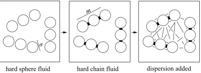
Figure 2.Schematic of three, non-associating molecules as they would be modelled using the PC-SAFT EoS. Each molecule is decomposed into spherical segments of diameterσ. The segments then form chains of lengthmthat interact via dispersion
forces. In this example, the three molecules have the same number of segmentsm= 3and diameterσ.
Results and Discussion
Isentropic properties
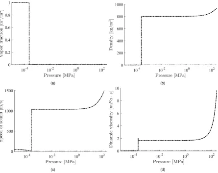
The first set of results in Figure 3 shows the properties that govern the behaviour of the diesel surrogate with respect to pressure. The properties were calculated maintaining the entropy of the fluid constant to that obtained at 324K and 5MPa. This temperature and pressure are chosen based on the theoretical outlet temperature for operation at 180MPa and a discharge coefficient of unity, i.e. the ideal case without friction losses, as calculated on a published paper using the same geometry [27]. Therefore, the pressure depends exclusively on density as in barotropic EoS. Isentropic properties are chosen instead of isothermal in order to take into account the thermal delay in cavitation, due to the heat transfer between the liquid and the vapour bubble [38].
The calculation of the vapour fraction, Figure 3a, is determined by minimizing the Gibbs Free Energy and applying the tangent plane criterion to find the most stable state(s) of the fluid system, according to a published algorithm [39] consisting of a stability analysis followed by a phase equilibrium calculation. For the conditions studied in these simulations, the vapor pressure for diesel fuel is 230Pa.
Although density, Figure 3b, is directly calculated from the pressure-explicit form of the equation of state the speed of sound and, particularly, the dynamic viscosity need certain considerations for their correct calculation.
Regarding the speed of sound shown in Figure 3c, its value in the single phase, i.e. when the pressure is greater than the vapor pressure, is directly calculated from its definition:
c= s
∂p ∂ρ
s
(5)
wherecis the speed of sound and()sindicates that the derivative is computed at constant entropy. However, when the fluid is in the two phase region, i.e. at a pressure lower than the vapor pressure, the speed of sound follows Wallis rule [40]:
1
ρc2 =
α ρVc2V
+1−α
ρLc2L
(6)
whereαis the volume vapor fraction and the subscriptsV andLstand for vapor and liquid phase.
Finally, in case of the dynamic viscosity in Figure 3d, it is calculated by using the method described in [41], while the mixing rule is taken from [35]. In case of the two phase region, the effective viscosity calculation is based on that of a published article [42]:
µ= (1−α)(1 +5
2α)µL+αµV (7)
Which at low gas concentration it takes into account the appearance of turbulent viscosity that overall increases the mixture viscosity [43].
Hydraulic characterisation
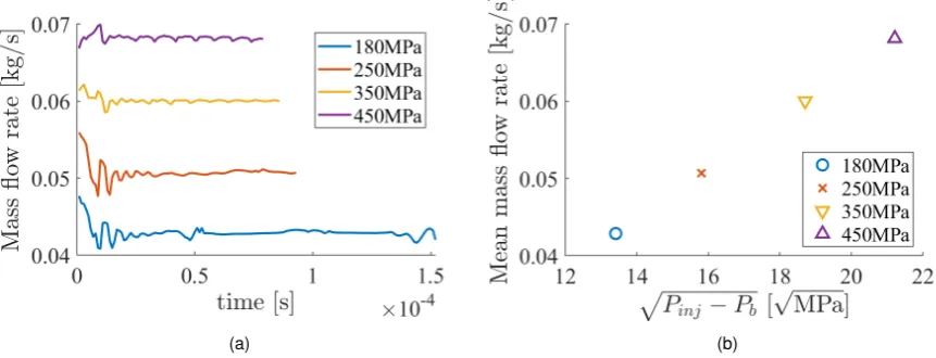
The mass flow rate is shown in Figure 5 for the four injection pressures 180, 250, 350 and 450MPa. These values were calculated at the exit of the orifice, it is presented against time in Figure 5a and averaged against the squared root of the pressure drop between the inlet and the outlet, in Figure 5b.
10-4 10-2 100 102 0
0.2 0.4 0.6 0.8 1
(a)
10-4 10-2 100 102 0
200 400 600 800 1000
(b)
10-4 10-2 100 102 0
500 1000 1500
(c)
10-4 10-2 100 102 0
2 4 6 8 10
[image:6.595.77.523.67.420.2](d)
Figure 3.Thermodynamic data used during the simulations for the diesel surrogate.
Internal flow
The averaged cavitation obtained in the simulations for the different injection pressures is shown as function of the position along the orifice in Figure 6a and the total volume occupied by vapor withα >1%in Figure 6b. For the total orifice lengthL,l= 0at the entrance andl=Lat the exit.
As shown, the dependence of the amount of cavitation with the injection pressure is proportionally inverse at the conditions studied in this paper, contrary to what is believed to be the typical trend. Regarding the total volume of vapor, it is found that the greatest change is found from 180MPa to 250MPa, with reduced, but still present, differences in the rest of cases following the same trend.
This trend in the amount of cavitation can be understood noticing that the rate of growth of the dynamic viscosity in Figure 3d is greatly enhanced at very high pressures. These high-pressure viscosities have an effect particularly in the sac flow, where the Reynolds number falls consistently with the injection pressure as shown in Figures 7 and 8. Taking into account the definition of the Reynolds number:
Re=V
νD (8)
where D, V and ν are the characteristic length of the injector nozzle, the velocity of the flow and the kinematic viscosity of the fluid given by the equation of state, respectively. Figure 9 shows the sac averaged values forV and
νfor each case. It can be seen that although both properties increase with the injection pressure, the rate at which the velocity increases is within 10-25% while for the kinematic viscosity it is between 50-100%. This tendency overall makes the Reynolds number to decrease with the injection pressure, making the flow more stable and therefore less prone to cavitate.
Summary and Conclusions
ILASS – Europe 2019, 2-4 Sep. 2019, Paris, France
[image:7.595.98.492.66.254.2](a) 180MPa (b) 250MPa (c) 350MPa (d) 450MPa
Figure 4.Averaged velocity in the injector for different injection pressures.
(a) (b)
Figure 5.Mass flow rate calculated at the exit of the orifice through time (a) and the averaged value against the squared root of the pressure drop(b).
pressures start from 180MPa and reach 450MPa. The collector back pressure is 5MPa. The density of the bulk fluid is assumed to vary according to a barotropic-like scheme, following an isentropic expansion.
Results show an increase in the mass flow rate, following the square root of the pressure difference law and also in the outlet velocity, both as expected. Surprisingly, the cavitation is significantly reduced as the injection pressure increases. A focused study on this particular phenomenon shows a significant decrease in the Reynolds number in the sac, therefore the flow is found to be more stable and the pressure drop along the nozzle is smaller. The reason for the lower Reynolds number is found on the heavy nature of Diesel fuels. While the sac average velocity increases an average of 15% between an injection pressure of 180MPa and 450MPa, the kinematic viscosity increases close to a 70%.
Regarding the future work, it is clear that a thorough study of the extreme cases is necessary as a refinement of the mesh may resolve smaller scales that with the current one are ommit. Additional, at extreme pressures, thermal effect are expected to be of greater importance and should be taken into account for future developments. Nevertheless, the results obtained in this work challenges the preconceived relation between injection pressure and cavitation production, which is of great importance for the reduction of pollution as the trend shows an increased interest on supercritical injection.
Acknowledgements
This project has received funding from the European Union Horizon-2020 Research and Innovation Programme. Grant Agreement No 675528.
[1] R. Lemaire, A. Faccinetto, E. Therssen, M. Ziskind, C. Focsa, and P. Desgroux. Experimental comparison of soot formation in turbulent flames of diesel and surrogate diesel fuels. Proceedings of the Combustion Institute, 32(1):737–744, 2009.
[image:7.595.75.506.284.449.2](a) (b)
Figure 6.Volume vapor fraction calculated during the simulations. (a) Averaged along the orifice and (b) Averaged volume in the nozzle covered byα >1%.
(a) 180MPa (b) 250MPa (c) 350MPa (d) 450MPa
Figure 7.Averaged Reynolds number in the injector for different injection pressures.
[3] Zhiyu Han, All Uludogan, Gregory J. Hampson, and Rolf D. Reitz. Mechanism of soot and NOx emission reduction using multiple-injection in a diesel engine. InSAE Technical Paper Series. SAE International, feb 1996.
[4] Lyle M. Pickett and Dennis L. Siebers. Soot in diesel fuel jets: effects of ambient temperature, ambient density, and injection pressure. Combustion and Flame, 138(1-2):114–135, jul 2004.
[5] M Gavaises. Flow in valve covered orifice nozzles with cylindrical and tapered holes and link to cavitation erosion and engine exhaust emissions. International Journal of Engine Research, 9(6):435–447, oct 2008. [6] D. P. Schmidt and M. L. Corradini. The internal flow of diesel fuel injector nozzles: A review. International
Journal of Engine Research, 2(1):1–22, feb 2001.
[7] Akira Sou, Shigeo Hosokawa, and Akio Tomiyama. Effects of cavitation in a nozzle on liquid jet atomization. International Journal of Heat and Mass Transfer, 50(17-18):3575–3582, aug 2007.
[8] J. Manin, M. Bardi, L.M. Pickett, and R. Payri. Boundary condition and fuel composition effects on injection processes of high-pressure sprays at the microscopic level. International Journal of Multiphase Flow, 83:267– 278, jul 2016.
[9] Weixing Yuan and Günter H. Schnerr. Numerical simulation of two-phase flow in injection nozzles: Interaction of cavitation and external jet formation. Journal of Fluids Engineering, 125(6):963, 2003.
[10] G.M Faeth, L.-P Hsiang, and P.-K Wu. Structure and breakup properties of sprays. International Journal of Multiphase Flow, 21:99–127, dec 1995.
[11] Hyun Kyu Suh and Chang Sik Lee. Effect of cavitation in nozzle orifice on the diesel fuel atomization charac-teristics. International Journal of Heat and Fluid Flow, 29(4):1001–1009, aug 2008.
[12] Raul Payri, S. Molina, F. J. Salvador, and J. Gimeno. A study of the relation between nozzle geometry, internal flow and sprays characteristics in diesel fuel injection systems. KSME International Journal, 18(7):1222–1235, jul 2004.
[13] R. Payri, F.J. Salvador, J. Gimeno, and L.D. Zapata. Diesel nozzle geometry influence on spray liquid-phase fuel penetration in evaporative conditions. Fuel, 87(7):1165–1176, jun 2008.
[image:8.595.95.495.273.460.2]cavi-ILASS – Europe 2019, 2-4 Sep. 2019, Paris, France
Figure 8.Mean Reynolds number calculated in the sac.
(a) (b)
Figure 9.(a) Mean velocity and (b) mean kinematic viscosity in the sac.
tation in large-scale diesel nozzles with tapered holes. Physics of Fluids, 21(5):052107, may 2009.
[15] F.J. Salvador, J. Martínez-López, M. Caballer, and C. De Alfonso. Study of the influence of the needle lift on the internal flow and cavitation phenomenon in diesel injector nozzles by CFD using RANS methods. Energy Conversion and Management, 66:246–256, feb 2013.
[16] W. H. Nurick. Orifice cavitation and its effect on spray mixing. Journal of Fluids Engineering, 98(4):681, 1976. [17] W Yuan. Modeling and computation of unsteady cavitation flows in injection nozzles. Mécanique &
Indus-tries, 2(5):383–394, oct 2001.
[18] Chawki Habchi, Nicolas Dumont, and Olivier Simonin. Multidimentional simulation of cavitating flows in diesel injectors by a homogeneous mixture modeling approach. Atomization and Sprays, 18(2):129–162, 2008. [19] Jules W. Lindau, Robert F. Kunz, David A. Boger, David R. Stinebring, and Howard J. Gibeling. High reynolds
number, unsteady, multiphase CFD modeling of cavitating flows. Journal of Fluids Engineering, 124(3):607, 2002.
[20] Ashok K. Singhal, Mahesh M. Athavale, Huiying Li, and Yu Jiang. Mathematical basis and validation of the full cavitation model. Journal of Fluids Engineering, 124(3):617, 2002.
[21] F. Peng Karrholm, Henry Weller, and Niklas Nordin. Modelling injector flow including cavitation effects for diesel applications. InVolume 2: Fora, Parts A and B. ASME, 2007.
[22] F J Salvador, S Hoyas, R Novella, and J Martínez-López. Numerical simulation and extended validation of two-phase compressible flow in diesel injector nozzles. Proceedings of the Institution of Mechanical Engineers, Part D: Journal of Automobile Engineering, 225(4):545–563, apr 2011.
[23] R. Payri, B. Tormos, J. Gimeno, and G. Bracho. The potential of large eddy simulation (LES) code for the modeling of flow in diesel injectors. Mathematical and Computer Modelling, 52(7-8):1151–1160, oct 2010. [24] F.J. Salvador, J. Martínez-López, J.-V. Romero, and M.-D. Roselló. Computational study of the cavitation
phe-nomenon and its interaction with the turbulence developed in diesel injector nozzles by large eddy simulation (LES). Mathematical and Computer Modelling, 57(7-8):1656–1662, apr 2013.
[25] B Mandumpala Devassy, W Edelbauer, and D Greif. Numerical simulation of the effect of 3d needle movement on cavitation and spray formation in a diesel injector. Journal of Physics: Conference Series, 656:012092, dec 2015.
[26] F Örley, S Hickel, S J Schmidt, and N A Adams. LES of cavitating flow inside a diesel injector including dynamic needle movement. Journal of Physics: Conference Series, 656:012097, dec 2015.
[image:9.595.75.504.252.415.2]including cavitation effects and correlation to erosion damage. Fuel, 175:26–39, jul 2016.
[28] N. Kolev. Multiphase Flow Dynamics 3: Turbulence, Gas Absorption and Release, Diesel Fuel Properties. Springer Verlag Berlin Heidelberg, 2002.
[29] Eric W Lemmon, Marcia L Huber, and Mark O McLinden. Nist standard reference database 23: Reference fluid thermodynamic and transport properties-refprop. 9.0. NIST, 2010.
[30] George Strotos, Phoevos Koukouvinis, Andreas Theodorakakos, Manolis Gavaises, and George Bergeles. Transient heating effects in high pressure diesel injector nozzles. International Journal of Heat and Fluid Flow, 51:257–267, feb 2015.
[31] Michele Battistoni, Sibendu Som, and Douglas E. Longman. Comparison of mixture and multifluid models for in-nozzle cavitation prediction. Journal of Engineering for Gas Turbines and Power, 136(6):061506, feb 2014. [32] Su Han Park, Hyun Kyu Suh, and Chang Sik Lee. Effect of bioethanol-biodiesel blending ratio on fuel spray
behavior and atomization characteristics. Energy & Fuels, 23(8):4092–4098, aug 2009.
[33] Su Han Park, Se Hun Kim, and Chang Sik Lee. Mixing stability and spray behavior characteristics of diesel-ethanol-methyl ester blended fuels in a common-rail diesel injection system. Energy & Fuels, 23(10):5228– 5235, oct 2009.
[34] Charles J. Mueller, William J. Cannella, J. Timothy Bays, Thomas J. Bruno, Kathy DeFabio, Heather D. Dettman, Rafal M. Gieleciak, Marcia L. Huber, Chol-Bum Kweon, Steven S. McConnell, William J. Pitz, and Matthew A. Ratcliff. Diesel surrogate fuels for engine testing and chemical-kinetic modeling: Compositions and properties. Energy & Fuels, 30(2):1445–1461, feb 2016.
[35] Alvaro Vidal, Carlos Rodriguez, Phoevos Koukouvinis, Manolis Gavaises, and Mark A McHugh. Modelling of diesel fuel properties through its surrogates using perturbed-chain, statistical associating fluid theory. Interna-tional Journal of Engine Research, 2019.
[36] FJ Salvador, J De la Morena, M Crialesi-Esposito, and J Martínez-López. Comparative study of the internal flow in diesel injection nozzles at cavitating conditions at different needle lifts with steady and transient sim-ulations approaches. Proceedings of the Institution of Mechanical Engineers, Part D: Journal of Automobile Engineering, 232(8):1060–1078, 2018.
[37] Phoevos Koukouvinis, Homa Naseri, and Manolis Gavaises. Performance of turbulence and cavitation models in prediction of incipient and developed cavitation. International Journal of Engine Research, 18(4):333–350, jul 2016.
[38] Fundamentals of Cavitation. Kluwer Academic Publishers, 2005.
[39] Daimler N. Justo-García, Fernando García-Sánchez, Ascención Romero-Martínez, Enrique Díaz-Herrera, and Eusebio Juaristi. Isothermal multiphase flash calculations with the PC-SAFT equation of state. InAIP Confer-ence Proceedings. AIP, 2008.
[40] Graham B Wallis. One-dimensional two-phase flow. International Journal of Heat and Mass Transfer, 14(8):1229, aug 1971.
[41] Oliver Lötgering-Lin and Joachim Gross. Group contribution method for viscosities based on entropy scaling using the perturbed-chain polar statistical associating fluid theory. Industrial & Engineering Chemistry Re-search, 54(32):7942–7952, aug 2015.
[42] D.R.H. Beattie and P.B. Whalley. A simple two-phase frictional pressure drop calculation method. International Journal of Multiphase Flow, 8(1):83–87, feb 1982.
![Table 1. Molar composition for the diesel surogate [34] modelled here. Boiling points at 0.1 MPa taken from the literature.](https://thumb-us.123doks.com/thumbv2/123dok_us/1357301.89245/3.595.116.487.476.702/table-molar-composition-diesel-surogate-modelled-boiling-literature.webp)