A NEW DATA TRANSFER SCHEME
BASED ON BANDWIDTH
ALLOCATION FOR VIRTUAL
PRIVATE NETWORKS
Mahalakshmi C1, Ramaswamy M2, Alamelu Nachiappan3
1
Lecturer (Senior Scale) in Electrical Engineering, Annamalai University, Annamalai Nagar – 608 002,Tamil Nadu, India. Ph: +91 98654 17244,
2
Professor of Electrical Engineering, Annamalai University
3
Assistant Professor of Electrical Engineering, Pondicherry Engineering College, Puducherry.
ABSTRACT
This paper attempts to develop a data transfer scheme with a view to sufficiently provision the hose model of the Virtual Private Network (VPN) and accomplish the desired degree of performance. The basic idea is to extract a service comparable to that of a private dedicated network with leased lines for the endpoints of the VPN. The service providers are expected to guarantee the required bandwidth, in order to address Quality of Service (QoS) issues while employing a VPN over a shared network. Thus a tree based mechanism is generated through which well defined resource management procedures are devised to optimize the available bandwidth. The data packets forwarded through such predetermined paths serve to ensure secure communication between customer sites. The NS2 based simulation results are included to demonstrate the merits of the designed approach and highlight the suitability of VPN for real time applications.
Keywords: Tree routing, QoS, VPN, Bandwidth, Performance metrics 1. INTRODUCTION
A Virtual Private Network (VPN) is an entity where remote locations are connected over a shared provider environment. It establishes connectivity between a set of geographically dispersed endpoints in a network infrastructure. They offer customers with predictable and safe network connections over a public network.
The phenomenon of routing in VPN involves the manner in which the endpoints are connected. The routing is a very significant issue because it is generally required to minimize the total amount of bandwidth reserved for the network. The VPN endpoints are connected through different structures and each result in different amounts of bandwidth requirements. A tree is considered to be the most scalable structure since it is simple and require fewer labels in setting up the paths. Moreover in terms of bandwidth, a tree allows greater sharing than a general sub graph [1]. It is in this direction, that the endpoints in the VPN are connected using a tree.
The number of endpoints in a VPN is continuously growing due to the overwhelming success of Internet Protocol (IP-VPN) networking topologies. Communication patterns between endpoints are thus difficult to forecast and the loads between pairs of endpoints unpredictable [2]. Besides, it may not also be possible to exactly specify the QoS requirements in such a situation. Therefore a definite routing scheme is essential to cater to the present variable traffic scenario.
the cost of laying a VPN supporting different traffic types and service classes on a given topology, while meeting QoS requirements [8].
A Virtual Private Network (VPN) aims to emulate the services provided by a Private Network over the shared Internet. The endpoints of the VPN are connected using links. Supporting QoS connections requires the creation of routing mechanisms that computes the QoS paths such that these paths satisfy the QoS constraints. Resilience to failures, on the other hand, is achieved by providing, each primary QoS path, a set of alternative QoS paths, upon a failure of either a link or a node. The idea is to minimize the total bandwidth reserved on the backup edges. The above objectives, coupled with the need to minimize the global use of network resources be a major consideration of the routing process. Hence, the new algorithm envisages to construct a tree topology and guarantee to offer acceptable performance metrics.
2. PROBLEM DESCRIPTION
The basic issue in the use of VPN is to identify a suitable procedure for routing the resources between the chosen source and destination. It is proposed to develop a tree based routing algorithm and employ the MPLS protocol to implement the transfer of data that can result in significant capacity savings to the service provider and guarantee satisfactory performance. The scheme is to be evaluated through performance indices that portray the efficiency of the topology. Besides it also includes obtaining the response on the occurrence of a contingency in the data transfer paths.
3. PROPOSED SCHEME
The basic objective is to design a data transfer mechanism suitable for VPN such that it optimizes the available bandwidth and extract the desired Quality of Services (QoS). The philosophy is to create trees involving all the VPN nodes in the system model and enforce the passage of traffic only through the predetermined paths. It in other words means the algorithm ensures that data transfer can only be through a tree created specifically for the purpose. In addition, it is envisaged to investigate the performance of the network when the data are re-routed on the occurrence of a contingency in the existing path.
A VPN graphically represented in figure 1 consists of a network where all customers’ hosts can communicate with each other without using the service provider network is called a site. The CE (Customer Edge) device is installed at the border of the customer site and the customer host devices connect to the CE device. A PE (Provider Edge) a device, directly connected to the CE device resides in the service provider’s network. The service provider offers VPN service by configuring VPN tunnels between PE devices. The forwarded packets that are received at one end of the VPN tunnel may not enter the tunnel except through one of the VPN tunnel endpoints [9]. Thus, the VPN tunnel functions as a virtual private line.
Figure 1. VPN Architecture
A hose is a service interface that is used to abstract the appropriate performance from the network. It is characterized by the aggregate traffic to and from one endpoint to a set of other endpoints in the same VPN and guarantees an associate performance. It is a simple service model for IP-VPN to emulate the private line. It requires a customer to acquire a set of allocations of specific bandwidth on paths between sources and destination pairs of endpoints of the VPN [10].
management challenges for the provider, these difficulties can be addressed by statistical multiplexing or resizing techniques, applied either separately or in a combined form [11].
The emergence of Multi-Protocol Label Switching (MPLS) protocol has offered an attractive solution to the process of routing in VPN. It provides a connection-oriented, QoS-based traditional, connectionless, best effort approach that allows the VPN services to extract performance at required levels. It is in fact a packet forwarding approach, the essence of which is to assign packet flows to Label Switched Paths (LSPs). It benefits both from circuit-switched and packet-switched network attributes and integrates wide variety of protocols on to the data link layer. Therefore MPLS, a network layer independent protocol is highly reliable, ensures minimum bandwidth and supports variety of QoS criteria.
VPNs can be constructed through the use of different MPLS Forward Equivalent Classes (FECs). FEC is used to define traffic that is forwarded in the same manner through a MPLS network. Thus, different FECs can be used to classify traffic from different VPNs which may or may not use the same path and may or may not share a portion of the network bandwidth. The path through an MPLS network can be a sink-tree path ending at one exit node or point-to-point paths [4].
A service provider has to be concerned with capacity provisioning and routing involving VPNs that have different service classes and topologies over the same network infrastructure. In addition, in designing a VPN, it is required to ensure scalability issues in order to support a large number of customers. In other words, a well-designed VPN must be easy to manage and attain bandwidth efficiency. It implies that the number of label switched paths (LSPs) and the required labels must be kept small over a MPLS network. In terms of efficiency, the different levels of traffic aggregation may be considered, for example, aggregation of traffic from different VPNs belonging to the same Classes of Services (CoS), aggregation of traffic from the same VPNs exiting at the same egress node, etc. The use of sink-tree paths in MPLS allows the VPN design problem to differ from those in traditional connection-oriented networks. The traffic of different VPNs with the same QoS requirement may or may not be carried on the same routing tree. Therefore the question how to construct a tree and incorporate it in the network design model still remains alive.
The network is modeled as a graph G = (V, E), where V is the set of nodes and E is the set of bidirectionallinks among the nodes in V. (i,j)and (j,i) are considered as two distinct links. Each link (i,j)is associated with a capacity Lij. In the hose model, each VPN specification consists of a set of VPN endpoints (PV) and the ingress and egress bandwidths of each VPN endpoints. The ingress bandwidth is the maximum amount of traffic a VPN endpoint receives, while the egress bandwidth is the maximum amount of traffic the VPN endpoint sends. For a nodeiP, both the hose ingress and egress bandwidths are denoted as Bi for a symmetric VPN.
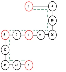
The system model shown in figure 2 comprises of four VPN nodes represented through red circles (0,1,5,6) and the other network nodes represented through black circles. A tree is used to connect the VPN endpoints/nodes. A tree T = (VT, ET) is a subgraph of G where PVTVandET E. It is essential that
enough bandwidth is reserved on the links of the tree to support the VPN.
Figure 2. System model
It is required to calculate the bandwidth requirement to be reserved on link (i,j) on T so that the link )
,
(i j supports the traffic going from Ti(i,j)toTj(i,j). In other words, it supports the traffic from VPN
out from Ti(i,j)is
P(i,j)a a i
B
while the maximum amount of traffic going to Tj(i,j)is
P(i,j)b b j
B
. Therefore, themaximum amount of traffic that goes through link
(
i
,
j
)
is min
(, ) (, ) , j i P b b j i P a a j i BB and this is precisely the bandwidth needed to be reserved on
(
i
,
j
)
which is denoted byCT(i,j).Though a number of tree configurations are possible for the model under consideration, it is proposed to explain the working of the scheme through three chosen typical trees. The passage of traffic exhibited through three identified trees is depicted in figures 3(a), 3(b) and 3(c). It is interesting to observe that the one seen in figure 3(a) follows the shortest path to traverse from the defined source to the desired destination while the trees seen in figures 3(b) and 3(c) follow relatively longer paths respectively in their pursuit to accomplish data transfer. The passage of traffic proceeds through (0-8-1-7-5-12-46-47-6) in the first path, (0-2-3-5-7-1-11-6) in the second path and (0-4-10-26-9-1-7-5-12-46-47-6) in the third path. The key feature to be noted is that the traffic progresses between the identified VPN source and destination nodes, ensuring that it passes through all the VPN nodes and there is no closed path in the traversed route.
Figure 3(a). Data transfer in Path 1
Figure 3(c). Data transfer in Path 3 4. SIMULATION RESULTS
The scheme simulated using Network Simulator (NS2) accords data transfer between the defined source and destination through three sample tree configured paths. The first stage of the investigation is to allocate the baseline bandwidth restrictions in the three assumed routes as 45*106, 70*106 and 105*106. A data message of size 1000 bytes is to be transmitted. A comprehensive set of measurements of packets received, Packet Delivery Ratio (PDR), routing delay and the energy expended through each of the available three paths are computed.
It is interesting to observe from Table 1 that the minimum bandwidth path enjoys the superior performance, in successfully routing the most number of packets with minimum delay. It incurs minimum expenditure of energy, enables the highest Packet Delivery Ratio (PDR) and offers the minimum energy*delay metric. The other paths with the subsequent higher bandwidths accomplish their relative degrees of performance in tune with the design of the algorithm.
Table 1. Performance Indices
Path/Parameter Bandwidth*106 Packets Received
PDR Routing Delay*10-3
Energy Consumed
Energy*Delay
Path 1 45 270 10 95 7.5 712.5
Path 2 70 260 7 110 10 1100
Path 3 105 255 6 290 16 4640
TheNS2 graphs seen in figures 4 through 8 is obtained for the different performance indices in the path with the minimum bandwidth. The usage of bandwidth with time to accomplish data transfer in this path is depicted in figure 4.
Figure 4. Bandwidth vs Time
Figure 5. Packets Received vs Time
Figure 6. Packet Delivery Ratio vs Time
Figure 7. Energy Consumed vs Time
The delay experienced, as data transmission is envisaged in the network is shown in figure 8. It is seen to be initially high on account of start up. However it is found to stabilize thereafter and remain reasonably low over the linear increase in the packets transferred.
Figure 8. Routing Delay vs Time
The energy consumption of the network apparently increases as seen in figure 9, when the size of the packets transfered between the source and destination are allowed to increase.
Figure 9. Energy Consumed vs No.of Packets
Figure 10. Packet Delivery Ratio vs No. of Packets
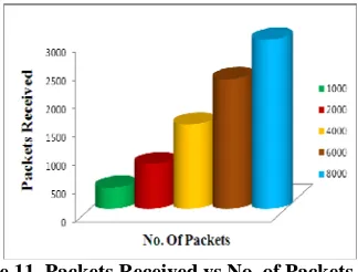
The proposed methodology for an increase in the number of transmitted packets offers a consistent raise in the PDR as evident from figure 10, contributes to enhance the energy efficiency. Figure 11 displays that larger the size of the packets transmitted, higher will be the number of packets received.
Figure 11. Packets Received vs No. of Packets
It follows that the tree based routing scheme enables a gradual decrease in the routing delay and a corresponding decline in the routing overhead for an increased packet size trasmission between the source and destinaton nodes under study as depicted in figure 12, thus offering a still higher performance of the network.
Figure 12. Routing Delay vs. No. of Packets
initially flowing through path1 is directed to follow path2 in the event of the failure of the link connecting nodes 8 and 1 and thereafter path3 because of the link failure between nodes 2 and 3. The snapshots displaying the passage of traffic in all the three cases are depicted in figures 13(a), 13(b) and 13(c).
Figure13(a). Data transfer on account of an exigency
Figure13(b). Data transfer on account of an exigency
Figure13(c). Data transfer on account of an exigency
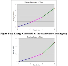
further noted from figure 14(c) that there is a slight increase in the energy consumed, besides an acceptable routing delay as seen from figure 14(d). However it is suffienct enough to cater to the ongoing traffic and therefore does not cause a disruption in the flow of data. It explains the capability of the algorithm to handle the ongoing traffic satisfactorily through rerouted paths and ensure a secure and stable delivery of data.
Figure 14(a). PDR on the occurrence of contingency
Figure 14(b). Packets Received on the occurrence of contingency
Figure 14(c). Energy Consumed on the occurrence of contingency
Figure 14(d). Routing Delay on the occurrence of contingency
It has been the order of the day to explore better and newer data transfer approaches owing to the inordinate increase in traffic and to keep abreast of the technological developments. It is in this prelude that a tree based routing algorithm suitable for VPN has been formulated and its performance evaluated through NS2 simulation. The metrics of three different sample tree configurations have been compared to bring out the merits of the proposed methodology. The NS2 graphs of the minimum bandwidth path have been portrayed to highlight its superior performance. It has been brought out that this path outperforms others in terms of higher PDR and number of packets received in addition to accomplishing data transmission with minimum delay and energy consumption. The algorithm has been designed with a facility to cater to the occurrence of exigencies and thus tailors the network to be robust in its operation.The fact that the proposed routing strategy yields the best performance in the minimum bandwidth path will go a long way in ensuring optimal use of bandwidth in the emerging traffic congested world.
REFERENCES
[1]Tat Wing Chim, King-Shan Lui, Kwan L. Yeung and Chi Ping Wong, Routing Algorithm for Provisioning Symmetric Virtual Private Networks in the Hose Model, IEEE GLOBECOM 2005 proceedings, pp.802-806.
[2] N. G. Duffield P. Goyal A. Greenberg P. Mishra K. K. Ramakrishnan and J. E. van der Merwe, Resource Management With Hoses: Point-to- Cloud Services for Virtual Private Networks, IEEE/ACM Transactions on Networking, pp. 679 – 692, Oct. 2002.
[3] A. Juttner, I. Szabo, and A. Szentesi, On Bandwidth Efficiency of the Hose Resource Management Model in Virtual Private Networks, in IEEE Proceedings of the INFOCOM ’03, pp. 386 – 395, 2003.
[4] Anotai Srikitja and David Tipper , QoS-based Virtual Private Network Design for an MPLS network, Dept. of Information Science and Telecommunications, University of Pittsburgh, Pittsburgh.
[5] R.Ravi, Dr. S.RadhaKrishnan , Enhanced Cost Optimized VPN Provisioning Algorithm, IJCSNS International Journal of Computer Science and Network Security, Vol.8 No.2, pp. 116-121, February 2008.
[6] N. G. Duffield P. Goyal A. Greenberg P. Mishra K. K. Ramakrishnan and J. E. van der Merwe, Resource Management with Hoses: Point-to- Cloud Services for Virtual Private Networks, IEEE/ACM Transactions on Networking, pp. 679 – 692, Oct. 2002.
[7] Song.J, Kim.S, Lee. M, Lee. H, and Suda. T, Adaptive load distribution over multipath in MPLS networks, Proc. IEEE Int. Conf. Comm. (ICC), Anchorage, Alaska, pp. 233–237, May 2003.
[8] Yu-Liang Liu and Yeali S. Sun and Meng Chang Chen, MTRA: An On-Line Hose-Model VPN Provisioning Algorithm, Journal of Telecommunication Systems, Volume 31, Number 4, pp.379-398, April 2006.
[9] Yoshihiro Hara, Hiroyuki Ohsaki, Makoto Imase, Yoshitake Tajima, Masahiro Maruyoshi and Junichi Murayama, On Layered VPN Architecture for Enabling User-Based Multiply Associated VPNs , Information Networking, Springer Berlin / Heidelberg, Volume 3090/2004, pp.847-856, August 2004.
[10]Monia Ghobadi, Sudhakar Ganti, Gholamali C. Shoja, Resource Optimization algorithms to Provision a Virtual Private Network Using the Hose Model, The International Journal of Computer and Telecommunications Networking, Volume 52 , Issue 16, pp. 3130-3147, November 2008.
[11] A. Kumar, R. Rastogi, A. Silberschatz, and Bulent Yener, Algorithms for Provisioning Virtual Private Networks in the Hose Model, IEEE/ACM Transactions on Networking, pp. 565 – 578, August 2002.
[12] David Yen, Douglas Havelka, David C. Chou, Virtual private networks: a model for assessing alternatives, International Journal of Networking and Virtual Organizations, Vol. 1, No.1 pp. 91-113, 2002.
ACKNOWLEDGEMENT