December 2004
Version 1.0 December 2004
NETGEAR, Inc.
4500 Great America Parkway Santa Clara, CA 95054 USA
NETGEAR Wireless
Router Setup Manual
ii
December 2004 Trademarks
NETGEAR is a trademark of Netgear, Inc.
Microsoft, Windows, and Windows NT are registered trademarks of Microsoft Corporation. Other brand and product names are registered trademarks or trademarks of their respective holders. Statement of Conditions
In the interest of improving internal design, operational function, and/or reliability, NETGEAR reserves the right to make changes to the products described in this document without notice.
NETGEAR does not assume any liability that may occur due to the use or application of the product(s) or circuit layout(s) described herein.
Federal Communications Commission (FCC) Compliance Notice: Radio Frequency Notice This equipment has been tested and found to comply with the limits for a Class B digital device, pursuant to
part 15 of the FCC Rules. These limits are designed to provide reasonable protection against harmful interference in a residential installation. This equipment generates, uses, and can radiate radio frequency energy and, if not installed and used in accordance with the instructions, may cause harmful interference to radio communications. However, there is no guarantee that interference will not occur in a particular installation. If this equipment does cause harmful interference to radio or television reception, which can be determined by turning the equipment off and on, the user is encouraged to try to correct the interference by one or more of the following measures:
• Reorient or relocate the receiving antenna.
• Increase the separation between the equipment and receiver.
• Connect the equipment into an outlet on a circuit different from that to which the receiver is connected. • Consult the dealer or an experienced radio/TV technician for help.
EN 55 022 Declaration of Conformance
This is to certify that the Pre-N Wireless Router WGM124 is shielded against the generation of radio interference in accordance with the application of Council Directive 89/336/EEC, Article 4a. Conformity is declared by the application of EN 55 022 Class B (CISPR 22).
December 2004
iii Bestätigung des Herstellers/Importeurs
Es wird hiermit bestätigt, daß das Pre-N Wireless Router WGM124 gemäß der im BMPT-AmtsblVfg 243/1991 und Vfg 46/1992 aufgeführten Bestimmungen entstört ist. Das vorschriftsmäßige Betreiben einiger Geräte (z.B. Testsender) kann jedoch gewissen Beschränkungen unterliegen. Lesen Sie dazu bitte die Anmerkungen in der Betriebsanleitung. Das Bundesamt für Zulassungen in der Telekommunikation wurde davon unterrichtet, daß dieses Gerät auf den Markt gebracht wurde und es ist berechtigt, die Serie auf die Erfüllung der Vorschriften hin zu überprüfen.
Certificate of the Manufacturer/Importer
It is hereby certified that the Pre-N Wireless Router WGM124 has been suppressed in accordance with the conditions set out in the BMPT-AmtsblVfg 243/1991 and Vfg 46/1992. The operation of some equipment (for example, test
transmitters) in accordance with the regulations may, however, be subject to certain restrictions. Please refer to the notes in the operating instructions.
Federal Office for Telecommunications Approvals has been notified of the placing of this equipment on the market and has been granted the right to test the series for compliance with the regulations.
Customer Support
Refer to the Support Information Card that shipped with your Pre-N Wireless Router WGM124. World Wide Web
NETGEAR maintains a World Wide Web home page that you can access at the universal resource locator (URL) http://www.netgear.com. A direct connection to the Internet and a Web browser such as Internet Explorer or Netscape are required.
December 2004
iv
Model Number: WGM124
Publication Date: December 2004
Product Family: router
Product Name: Pre-N Wireless Router WGM124
Home or Business Product: Home
Contents v
Contents
Chapter 1
About This Guide
Audience, Conventions, and Formats ...1-1 How to Use This Manual ...1-2 How to Print this Manual ...1-3 Chapter 2
Getting to Know Your NETGEAR Wireless Router
Package Contents ...2-1 The Front Panel ...2-2 The Rear Panel ...2-2 Chapter 3
Connecting the Router to the Internet
Prepare to Install Your Wireless Router ...3-1 Connect the Wireless Router to Your Network ...3-1 Troubleshooting Tips ...3-2 How to Manually Configure Your Internet Connection ...3-3 NETGEAR Product Registration, Support, and Documentation ...3-5 Chapter 4
Optimizing Wireless Connectivity and Security
Observe Performance, Placement, and Range Guidelines ...4-1 Implement Appropriate Wireless Security ...4-2 Understanding Wireless Settings ...4-3 Information to Gather Before Changing Basic Wireless Settings ...4-5 Default Factory Settings ...4-6 Chapter 5
Doing Basic Router Housekeeping
Changing the Administrator Password ...5-1 Configuration File Management ...5-2 Restoring and Backing Up the Configuration ...5-2
vi Contents Upgrading the Wireless Router Software ...5-3 Chapter 6
Troubleshooting Common Problems
Basic Functioning ...6-1 Power Light Not On ...6-1 Lights Never Turn Off ...6-2 LAN or Internet (WAN) Port Lights Not On ...6-2 Troubleshooting the Web Configuration Interface ...6-2 Troubleshooting the ISP Connection ...6-3 Troubleshooting a TCP/IP Network Using a Ping Utility ...6-5 Testing the LAN Path to Your Router ...6-5 Testing the Path from Your Computer to a Remote Device ...6-6 Restoring the Default Configuration and Password ...6-7 Appendix A
Technical Specifications Appendix B
Network, Routing, and Firewall Basics
Related Publications ... B-1 Basic Router Concepts ... B-1 What is a Router? ... B-1 Routing Information Protocol ... B-2 IP Addresses and the Internet ... B-2 Netmask ... B-4 Subnet Addressing ... B-4 Private IP Addresses ... B-7 Single IP Address Operation Using NAT ... B-7 MAC Addresses and Address Resolution Protocol ... B-8 Related Documents ... B-9 Domain Name Server ... B-9 IP Configuration by DHCP ... B-10 Internet Security and Firewalls ... B-10 What is a Firewall? ... B-10 Stateful Packet Inspection ...B-11 Denial of Service Attack ...B-11
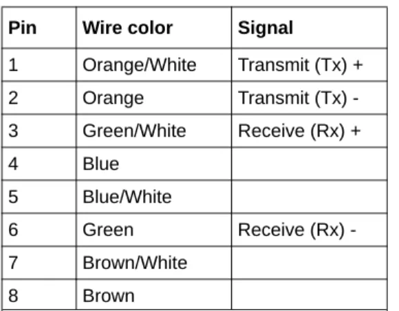
Contents vii Ethernet Cabling ...B-11
Category 5 Cable Quality ... B-12 Inside Twisted Pair Cables ... B-13 Uplink Switches, Crossover Cables, and MDI/MDIX Switching ... B-14 Appendix C
Preparing Your Network
What You Need To Use a Router with a Broadband Modem ... C-1 Cabling and Computer Hardware ... C-1 Computer Network Configuration Requirements ... C-1 Internet Configuration Requirements ... C-2 Where Do I Get the Internet Configuration Parameters? ... C-2 Record Your Internet Connection Information ... C-3 Preparing Your Computers for TCP/IP Networking ... C-3 Configuring Windows 95, 98, and Me for TCP/IP Networking ... C-4 Install or Verify Windows Networking Components ... C-4 Enabling DHCP to Automatically Configure TCP/IP Settings in Windows 95B, 98, and Me C-6
Selecting Windows’ Internet Access Method ... C-8 Verifying TCP/IP Properties ... C-8 Configuring Windows NT4, 2000 or XP for IP Networking ... C-9 Install or Verify Windows Networking Components ... C-9 DHCP Configuration of TCP/IP in Windows XP, 2000, or NT4 ... C-10 DHCP Configuration of TCP/IP in Windows XP ... C-10 DHCP Configuration of TCP/IP in Windows 2000 ... C-12 DHCP Configuration of TCP/IP in Windows NT4 ... C-15 Verifying TCP/IP Properties for Windows XP, 2000, and NT4 ... C-17 Configuring the Macintosh for TCP/IP Networking ... C-18 MacOS 8.6 or 9.x ... C-18 MacOS X ... C-18 Verifying TCP/IP Properties for Macintosh Computers ... C-19 Verifying the Readiness of Your Internet Account ... C-20 Are Login Protocols Used? ... C-20 What Is Your Configuration Information? ... C-20 Obtaining ISP Configuration Information for Windows Computers ... C-21 Obtaining ISP Configuration Information for Macintosh Computers ... C-22 Restarting the Network ... C-23
viii Contents Wireless Networking Basics
Wireless Networking Overview ... D-1 Infrastructure Mode ... D-1 Ad Hoc Mode (Peer-to-Peer Workgroup) ... D-2 Network Name: Extended Service Set Identification (ESSID) ... D-2 Wireless Channels ... D-2 WEP Wireless Security ... D-4 WEP Authentication ... D-4 WEP Open System Authentication ... D-5 WEP Shared Key Authentication ... D-6 Key Size and Configuration ... D-7 How to Use WEP Parameters ... D-8 WPA Wireless Security ... D-8 How Does WPA Compare to WEP? ... D-9 How Does WPA Compare to IEEE 802.11i? ... D-10 What are the Key Features of WPA Security? ... D-10
WPA Authentication: Enterprise-level User
Authentication via 802.1x/EAP and RADIUS ... D-12 WPA Data Encryption Key Management ... D-14 Is WPA Perfect? ... D-16 Product Support for WPA ... D-16 Supporting a Mixture of WPA and WEP Wireless Clients ... D-16 Changes to Wireless Access Points ... D-16 Changes to Wireless Network Adapters ... D-17 Changes to Wireless Client Programs ... D-18 Glossary
List of Glossary Terms ... G-1 Index
About This Guide 1
Chapter 1
About This Guide
This chapter describes the intended audience, scope, conventions, and formats of this manual.
Audience, Conventions, and Formats
This reference manual assumes that the reader has basic computer and Internet skills. However, basic computer network, Internet, and firewall technologies tutorial information is provided in the Appendices and on the Netgear Web site.
This guide uses the following typographical conventions:
This guide uses the following format to highlight special messages:
This manual is written for NETGEAR wireless routers. Table 1-1. Typographical Conventions
italics Emphasis, books, CDs, URL names
bold User input
SMALLCAPS Screen text, file and server names, extensions, commands, IP addresses
Note: This format is used to highlight information of importance or special interest.
Table 1-2. Manual Publication Details
Product Version Pre-N Wireless Router WGM124
Manual Publication Date December 2004
Note: Product updates are available on the NETGEAR Web site at http://kbserver.netgear.com.
2 About This Guide
How to Use This Manual
The HTML version of this manual includes the following:
• Buttons, and , for browsing forwards or backwards through the manual one page at a time
• A button that displays the table of contents and an button. Double-click on a link in the table of contents or index to navigate directly to where the topic is described in the manual.
• A button to access the full NETGEAR, Inc. online knowledge base for the product model.
NETGEAR Wireless Router Setup Manual
About This Guide 3
How to Print this Manual
To print this manual you can choose one of the following several options, according to your needs. • Printing a Page in the HTML View.
Each page in the HTML version of the manual is dedicated to a major topic. Use the Print
button on the browser toolbar to print the page contents. • Printing a Chapter.
Use the PDF of This Chapter link at the top left of any page.
– Click the “PDF of This Chapter” link at the top right of any page in the chapter you want to print. The PDF version of the chapter you were viewing opens in a browser window. Note: Your computer must have the free Adobe Acrobat reader installed in order to view and print PDF files. The Acrobat reader is available on the Adobe Web site at
http://www.adobe.com.
– Click the print icon in the upper left of the window.
Tip: If your printer supports printing two pages on a single sheet of paper, you can save paper and printer ink by selecting this feature.
• Printing the Full Manual.
Use the Complete PDF Manual link at the top left of any page.
– Click the Complete PDF Manual link at the top left of any page in the manual. The PDF version of the complete manual opens in a browser window.
– Click the print icon in the upper left of the window.
Tip: If your printer supports printing two pages on a single sheet of paper, you can save paper and printer ink by selecting this feature.
Getting to Know Your NETGEAR Wireless Router 2-1
Chapter 2
Getting to Know Your NETGEAR Wireless Router
NETGEAR wireless routers provide connections for multiple computers to the Internet through an external broadband access device such as a cable modem or DSL modem that is normally intended for use by a single computer. This chapter introduces the NETGEAR Pre-N Wireless Router WGM124.
Package Contents
The product package should contain the following items: • Pre-N Wireless Router WGM124.
• AC power adapter.
• A Category 5 (CAT5) Ethernet cable. • The Setup CD, including:
— This guide.
— Application Notes and other helpful information. • Registration, Warranty Card, and Support Information Card.
If any of the parts are incorrect, missing, or damaged, contact your NETGEAR dealer. Keep the carton, including the original packing materials, in case you need to return the router for repair.
2-2 Getting to Know Your NETGEAR Wireless Router
The Front Panel
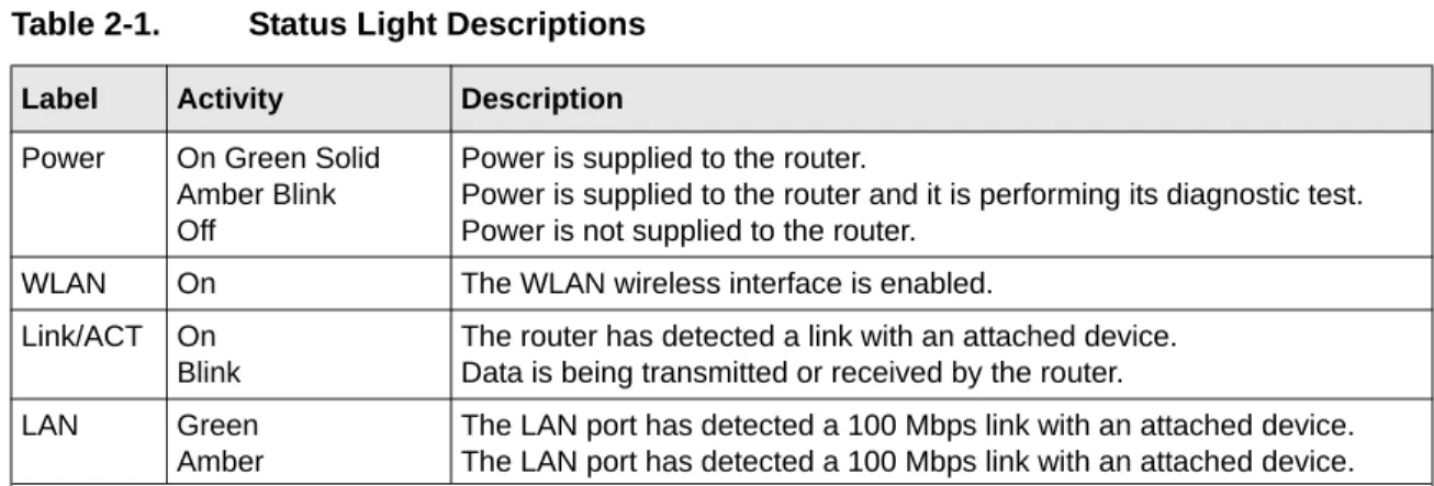
The front panel of the wireless router includes various status lights. You can use the status lights to verify connections.
The Rear Panel
The rear panel of the WGM124 router contains the items listed below. • AC power adapter outlet
• Four LAN ports
• Internet (WAN) Ethernet port for connecting the router to a cable or DSL modem • Factory default reset push button for Restoring the Default Configuration and Password
• One red status LED, which blinks when the default reset button is pushed. • Three wireless antennae
Table 2-1. Status Light Descriptions
Label Activity Description
Power On Green Solid
Amber Blink Off
Power is supplied to the router.
Power is supplied to the router and it is performing its diagnostic test. Power is not supplied to the router.
WLAN On The WLAN wireless interface is enabled.
Link/ACT On Blink
The router has detected a link with an attached device. Data is being transmitted or received by the router. LAN Green
Amber
The LAN port has detected a 100 Mbps link with an attached device. The LAN port has detected a 100 Mbps link with an attached device.
Connecting the Router to the Internet 3-1
Chapter 3
Connecting the Router to the Internet
This chapter describes how to set up the router on your local area network (LAN) and connect to the Internet. You will find out how to configure your wireless router for Internet access.
Follow these instructions to set up your router.
Prepare to Install Your Wireless Router
• For Cable Modem Service: When you perform the wireless router setup steps be sure to use the computer you first registered with your cable ISP.
• For DSL Service: You may need information such as the DSL login name/e-mail address and password in order to complete the wireless router setup.
Before proceeding with the wireless router installation, familiarize yourself with the contents of the Setup CD, especially this manual and the tutorials for configuring computers for networking.
Connect the Wireless Router to Your Network
Use the instructions in the Installation Guide to connect the wireless router to the Internet and configure the wireless functions.
3-2 Connecting the Router to the Internet
Troubleshooting Tips
Here are some tips for correcting simple problems you may have. Be sure to restart your network in this sequence:
1) Turn off the modem, wireless router, and computer; 2) Turn on the modem, wait two minutes; 3) Turn on the wireless router and wait 1 minute; 4) Turn on the computer. Make sure the Ethernet cables are securely plugged in.
• The Internet status light on the wireless router will be lit if the Ethernet cable to the wireless router from the modem is plugged in securely and the modem and wireless router are turned on.
• For each powered on computer connected to the wireless router with a securely plugged in Ethernet cable, the corresponding wireless router LAN port status light will be lit. The label on the bottom of the wireless router identifies the number of each LAN port.
Make sure the wireless settings in the computer and router match exactly.
The Wireless Network Name (SSID) and security settings of the router and wireless computer must match exactly.
Make sure the network settings of the computer are correct.
• LAN and wirelessly connected computers must be configured to obtain an IP address
automatically via DHCP. Please see Appendix C, “Preparing Your Network” or the animated tutorials on the CD for help with this.
• Some cable modem ISPs require you to use the MAC address of the computer registered on the account. If so, in the Router MAC Address section of the Basic Settings menu, select “Use this Computer’s MAC Address.” The router will then capture and use the MAC address of the computer that you are now using. You must be using the computer that is registered with the ISP. Click Apply to save your settings. Restart the network in the correct sequence.
Check the router status lights to verify correct router operation.
• If the Power light does not turn solid green within 2 minutes after turning the router on, reset the router according to the instructions in “Restoring the Default Configuration and Password”
on page 6-7.
• If the Wireless light does not come on, verify that the wireless feature is turned on according to the instructions in “Understanding Wireless Settings” on page 4-3.
NETGEAR Wireless Router Setup Manual
Connecting the Router to the Internet 3-3
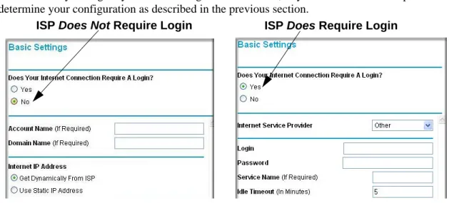
How to Manually Configure Your Internet Connection
You can manually configure your router using the menu below, or you can allow the Setup Wizard to determine your configuration as described in the previous section.
Figure 3-1: Browser-based configuration Basic Settings menus
You can manually configure the router using the Basic Settings menu shown in Figure 3-1 using these steps:
1. Connect to the wireless router by typing http://www.routerlogin.net in the address field of your browser, then click Enter.
2. For security reasons, the wireless router has its own user name and password. When prompted, enter admin for the router user name and password for the router password, both in lower case letters.
3. Click Basic Settings on the Setup menu.
4. If your Internet connection does not require a login, click No at the top of the Basic Settings menu and fill in the settings according to the instructions below. If your Internet connection does require a login, click Yes, and skip to step 5.
a. Enter your Account Name (may also be called Host Name) and Domain Name. These parameters may be necessary to access your ISP’s services such as mail or news servers.
3-4 Connecting the Router to the Internet
b. Internet IP Address:
If your ISP has assigned you a permanent, fixed (static) IP address for your computer, select “Use static IP address”. Enter the IP address that your ISP assigned. Also enter the netmask and the Gateway IP address. The Gateway is the ISP’s router to which your router will connect.
c. Domain Name Server (DNS) Address:
If you know that your ISP does not automatically transmit DNS addresses to the router during login, select “Use these DNS servers” and enter the IP address of your ISP’s Primary DNS Server. If a Secondary DNS Server address is available, enter it also. Note: If you enter an address here, restart the computers on your network so that these settings take effect.
d. Router’s MAC Address:
This section determines the Ethernet MAC address that will be used by the router on the Internet port. Some ISPs will register the Ethernet MAC address of the network interface card in your computer when your account is first opened. They will then only accept traffic from the MAC address of that computer. This feature allows your router to masquerade as that computer by “cloning” its MAC address.
To change the MAC address, select “Use this Computer’s MAC address.” The router will then capture and use the MAC address of the computer that you are now using. You must be using the one computer that is allowed by the ISP. Or, select “Use this MAC address” and type it in here.
e. Click Apply to save your settings.
5. If your Internet connection does require a login, fill in the settings according to the instructions below. Select Yes if you normally must launch a login program such as Enternet or WinPOET in order to access the Internet.
Note: After you finish setting up your router, you will no longer need to launch the ISP’s login program on your computer in order to access the Internet. When you start an Internet
application, your router will automatically log you in.
NETGEAR Wireless Router Setup Manual
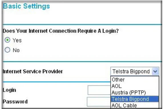
Connecting the Router to the Internet 3-5
Figure 3-2: Basic Settings ISP list
Note: Not all ISPs are listed here. The ones on this list have special requirements. b. The screen will change according to the ISP settings requirements of the ISP you select. c. Fill in the parameters for your Internet service provider.
d. Click Apply to save your settings. Click the Test button to verify you have Internet access.
NETGEAR Product Registration, Support, and Documentation
Register your product at http://www.NETGEAR.com/register. Registration is required before you can use our telephone support service.
Product updates and Web support are always available by going to:
http://kbserver.netgear.com.
When the wireless router is connected to the Internet, click the Knowledge Base or the Documentation link under the Web Support menu to view support information or the documentation for the wireless router.
Optimizing Wireless Connectivity and Security 4-1
Chapter 4
Optimizing Wireless Connectivity and Security
This chapter describes how to configure the wireless features of your wireless router. In planning your wireless network, you should consider the level of security required. You should also select the physical placement of your firewall in order to maximize the network speed.
The full manual with detailed how to instructions is available on line at
http://kbserver.netgear.com/ and via the Documentation link in the configuration utility of the wireless router.
Observe Performance, Placement, and Range Guidelines
The operating distance or range of your wireless connection can vary significantly based on the physical placement of the wireless firewall. The latency, data throughput performance, and notebook power consumption of wireless adapters also vary depending on your configuration choices.
For best results, place your firewall:
• Near the center of the area in which your computers will operate.
• In an elevated location such as a high shelf where the wirelessly connected computers have line-of-sight access (even if through walls).
• Away from sources of interference, such as computers, microwaves, and 2.4 GHz cordless phones.
• Away from large metal surfaces.
The time it takes to establish a wireless connection can vary depending on both your security settings and placement. WEP or WPA-PSK connections can take slightly longer to establish.
Note: Failure to follow these guidelines can result in significant performance degradation or inability to wirelessly connect to the router. For complete range/ performance specifications, please see Appendix A, “Technical Specifications.”
4-2 Optimizing Wireless Connectivity and Security
Implement Appropriate Wireless Security
Unlike wired network data, your wireless data transmissions can be received well beyond your walls by anyone with a compatible adapter. For this reason, use the security features of your wireless equipment. The wireless router provides highly effective security features which are covered in detail in this chapter. Deploy the security features appropriate to your needs. There are several ways you can enhance the security of your wireless network.
• Restrict Access Based on MAC Address. You can restrict access to only trusted computers so that unknown computers cannot wirelessly connect to the WGM124. MAC address filtering adds an obstacle against unwanted access to your network, but the data broadcast over the wireless link is fully exposed.
• Turn Off the Broadcast of the Wireless Network Name SSID. If you disable broadcast of the SSID, only devices that have the correct SSID can connect. This nullifies the wireless network ‘discovery’ feature of some products such as Windows XP, but the data is still fully exposed to a determined snoop using specialized test equipment like wireless sniffers. • WEP. Wired Equivalent Privacy (WEP) data encryption provides data security. WEP Shared
Key authentication and WEP data encryption will block all but the most determined eavesdropper.
• WPA-PSK. Wi-Fi Protected Access (WPA) data encryption provides strong data security. WPA-PSK will block eavesdropping. Because this is a new standard, wireless device driver and software availability may be limited.
• Turn Off the Wired LAN. If you disable the wireless LAN, wireless devices cannot communicate with the router at all. You might choose to turn off the wireless the LAN when you are away and the others in the household all use wired connections.
Note: Indoors, computers can connect over 802.11b/g wireless networks at ranges of up to 300 feet. Such distances can allow for others outside of your immediate area to access your network.
NETGEAR Wireless Router Setup Manual
Optimizing Wireless Connectivity and Security 4-3
Understanding Wireless Settings
To configure the Wireless settings of your firewall, click the Wireless link in the main menu of the browser interface.
• Name (SSID). The SSID is also known as the wireless network name. Enter a value of up to 32 alphanumeric characters. In a setting where there is more than one wireless network, different wireless network names provide a means for separating the traffic. Any device you want to participate in a particular wireless network will need to use this SSID for that network. • Region. This field identifies the region where the WGM124 can be used. It may not be legal to
operate the wireless features of the wireless router in a region other than one of those identified in this field.
• Channel. This field determines which operating frequency will be used. It should not be necessary to change the wireless channel unless you notice interference problems with another nearby access point.
• Mode. This field determines which data communications protocol will be used.
• Security Options. These options are the wireless security features you can enable. The table below identifies the various basic wireless security options.
• Allow Broadcast of Name (SSID). If you disable broadcast of the SSID, only devices that have the correct SSID can connect. Disabling SSID broadcast nullifies the wireless network ‘discovery’ feature of some products such as Windows XP.
• Enable Wireless Access Point. If you disable the wireless access point, wireless devices cannot connect to the WGM124.
• Wireless Card Access List. When the Trusted PCs Only radio button is selected, the WGM124 checks the MAC address of the wireless station and only allows connections to computers identified on the trusted computers list.
4-4 Optimizing Wireless Connectivity and Security Table 4-1. Basic Wireless Security Options
Field Description Automatic No wireless security.
WEP WEP offers the following options: • Open System
With Open Network Authentication and 64- or 128-bit WEP Data Encryption, the WGM124 does perform 64- or 128-bit data encryption but does not perform any authentication. • Shared Key
Shared Key authentication encrypts the SSID and data.
Choose the Encryption Strength (64- or 128-bit data encryption). Manually enter the key values or enter a word or group of printable characters in the Passphrase box. Manually entered keys are case sensitive but passphrase characters are not case sensitive. Note: Not all wireless adapter configuration utilities support passphrase key generation. • Auto
WPA-PSK WPA-Pre-shared Key does perform authentication, uses 128-bit data encryption and dynamically changes the encryption keys making it nearly impossible to circumvent.
Enter a word or group of printable characters in the Password Phrase box. These characters are case sensitive.
Note: Not all wireless adapter configuration utilities support WPA. Furthermore, client software is required on the client. Windows XP and Windows 2000 with Service Pack 3 do include the client software that supports WPA. Nevertheless, the wireless adapter hardware and driver must also support WPA.
NETGEAR Wireless Router Setup Manual
Optimizing Wireless Connectivity and Security 4-5
Information to Gather Before Changing Basic Wireless Settings
Before customizing your wireless settings, print this form and record the following information. • Wireless Network Name (SSID): ______________________________
The SSID, identifies the wireless network. You can use up to 32 alphanumeric characters. The SSID is case sensitive. The SSID in the wireless adapter card must match the SSID of the wireless router. In some configuration utilities (such as in Windows XP), the term “wireless network name” is used instead of SSID.
• If WEP Authentication is Used. Circle one: Open System, Shared Key, or Auto.
Note: If you select Shared Key, the other devices in the network will not connect unless they are set to Shared Key as well and are configured with the correct key.
– WEP Encryption key size. Choose one: 64-bit or 128-bit. Again, the encryption key size must be the same for the wireless adapters and the wireless router.
– Data Encryption (WEP) Keys. There are two methods for creating WEP data encryption keys. Whichever method you use, record the key values in the spaces below.
• Passphrase method. ______________________________ These characters are case sensitive. Enter a word or group of printable characters and click the Generate Keys button. Not all wireless devices support the passphrase method.
• Manual method. These values are not case sensitive. For 64-bit WEP, enter 10 hex digits (any combination of 0-9 or a-f). For 128-bit WEP, enter 26 hex digits.
Key 1: ___________________________________ Key 2: ___________________________________ Key 3: ___________________________________ Key 4: ___________________________________ • If WPA-PSK Authentication is Used.
– Passphrase: ______________________________ These characters are case sensitive. Enter a word or group of printable characters. When you use WPA-PSK, the other devices in the network will not connect unless they are set to WPA-PSK as well and are configured with the correct Passphrase.
Use the procedures described in the reference manual to configure the WGM124. The reference manual is available on line at http://kbserver.netgear.com.
4-6 Optimizing Wireless Connectivity and Security
Default Factory Settings
When you first receive your WGM124, the default factory settings are shown below. You can restore these defaults with the Factory Default Restore button on the rear panel. After you install the wireless router, use the procedures below to customize any of the settings to better meet your networking needs.
Warning: The Network Name (SSID) and passphrase are case sensitive. Typing nETgear_11a for the 802.11a SSID will not work.
WIRELESS FEATURE DEFAULT SETTING Wireless Access Point Enabled
Wireless Access List (MAC Filtering) All wireless stations allowed SSID broadcast Enabled
Network Name (SSID) NETGEAR
Doing Basic Router Housekeeping 5-1
Chapter 5
Doing Basic Router Housekeeping
This chapter describes how to use some of the maintenance features of your Pre-N Wireless Router WGM124. These features can be found by clicking on the Maintenance heading in the Main Menu of the browser interface. Other maintenance features not presented in this chapter can be found accessed via links in the browser interface of the wireless router to the User Guide and in the help screens.
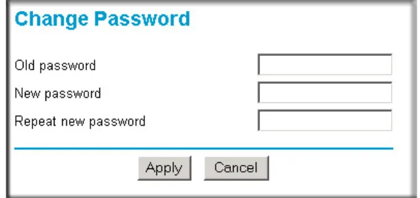
Changing the Administrator Password
The default password for the wireless router’s Web Configuration Manager is password. Change this password to a more secure password.
From the Main Menu of the browser interface, under the Maintenance heading, select Set Password to bring up the menu shown below.
Figure 5-1: Set Password menu
Note: Before changing the wireless router password, follow the instructions under
“Configuration File Management” on page 5-2 to save your configuration settings. If you
forget the new password, you will have to reset the wireless router back to the factory defaults to be able to log in using the default password of password. This means you will have to restore all the wireless router configuration settings. If you ever have to reset the wireless router back to the factory defaults, you can restore your settings from the backup configuration file.
5-2 Doing Basic Router Housekeeping
To change the password, first enter the old password, then enter the new password twice. Click Apply.
Configuration File Management
The configuration settings of the wireless router are stored within the wireless router in a
configuration file. This file can be saved (backed up) to a user’s PC, retrieved (restored) from the user’s PC, or cleared to factory default settings.
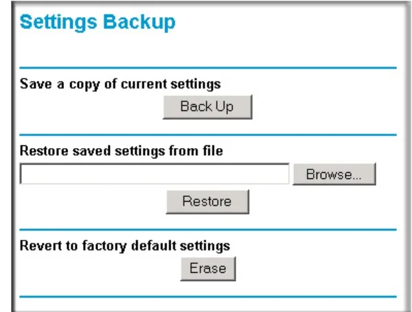
From the Main Menu of the browser interface, under the Maintenance heading, select the Settings Backup heading to bring up the menu shown below.
Figure 5-2: Settings Backup menu
Three options are available, and are described in the following sections.
Restoring and Backing Up the Configuration
The Restore and Backup options in the Settings Backup menu allow you to save and retrieve a file containing your wireless router’s configuration settings.
To save your settings, click the Backup button. Your browser will extract the configuration file from the wireless router and will prompt you for a location on your PC to store the file. You can give the file a meaningful name at this time, such as pacbell.cfg.
NETGEAR Wireless Router Setup Manual
Doing Basic Router Housekeeping 5-3
To restore your settings from a saved configuration file, enter the full path to the file on your PC or click the Browse button to browse to the file. When you have located it, click the Restore button to send the file to the wireless router. The wireless router will then reboot automatically.
Warning: Do not interrupt the reboot process.
Erasing the Configuration
It is sometimes desirable to restore the wireless router to original default settings. This can be done by using the Erase function, which will restore all factory settings. After an erase, the wireless router's password will be password, the LAN IP address will be 192.168.1.1, and the wireless router's DHCP client will be enabled.
To erase the configuration, click the Erase button.
To restore the factory default configuration settings without knowing the login password or IP address, you must use the Default Reset button on the rear panel of the wireless router. See
“Restoring the Default Configuration and Password” on page 6-7.
Upgrading the Wireless Router Software
The routing software of the wireless router is stored in FLASH memory, and can be upgraded as new software is released by NETGEAR. Upgrade files can be downloaded from the NETGEAR Web site. If the upgrade file is compressed (.ZIP file), you must first extract the file before sending it to the wireless router. The upgrade file can be sent to the wireless router using your browser. Note: The Web browser used to upload new firmware into the wireless router must support HTTP uploads. NETGEAR recommends using Microsoft Internet Explorer or Netscape Navigator 3.0 or above.
From the Main Menu of the browser interface, under the Maintenance heading, select the Router Upgrade link display the menu shown below.
Note: Before upgrading the wireless router software, use the wireless router backup utility to save your configuration settings. Any wireless router upgrade will revert the wireless router settings back to the factory defaults. After completing the upgrade, you can restore your settings from the backup.
5-4 Doing Basic Router Housekeeping Figure 5-3: Router Upgrade menu
To upload new firmware:
1. Download and unzip the new software file from NETGEAR.
2. In the Router Upgrade menu, click the Browse button and browse to the location of the upgrade file
3. Click Upload.
Note: When uploading software to the wireless router, it is important not to interrupt the Web browser by closing the window, clicking a link, or loading a new page. If the browser is interrupted, it may corrupt the software. When the upload is complete, your wireless router will automatically restart. The upgrade process will typically take about one minute. In some cases, you may need to reconfigure the wireless router after upgrading.
Troubleshooting Common Problems 6-1
December 2004
Chapter 6
Troubleshooting Common Problems
This chapter gives information about troubleshooting your Pre-N Wireless Router WGM124. After each problem description, instructions are provided to help you diagnose and solve the problem.
Basic Functioning
After you turn on power to the router, the following sequence of events should occur: 1. When power is first applied, verify that the Power light is on.
2. After approximately 10 seconds, verify that: a. The power light is solid green.
b. The LAN port lights are lit for any local ports that are connected. c. The Link/ACT light is lit.
If a port’s light is lit, a link has been established to the connected device. If any of these conditions does not occur, refer to the appropriate following section.
Power Light Not On
If the Power and other lights are off when your router is turned on:
• Make sure that the power cord is properly connected to your router and that the power supply adapter is properly connected to a functioning power outlet.
• Check that you are using the power adapter supplied by NETGEAR for this product. If the error persists, you have a hardware problem and should contact technical support.
6-2 Troubleshooting Common Problems
December 2004
Lights Never Turn Off
When the router is turned on, the lights turns on for about 10 seconds and then turn off. If all the lights stay on, there is a fault within the router.
If all lights are still on one minute after power up: • Cycle the power to see if the router recovers.
• Clear the router’s configuration to factory defaults. This will set the router’s IP address to 192.168.1.1. This procedure is explained in “Restoring the Default Configuration and
Password” on page 6-7.
If the error persists, you might have a hardware problem and should contact technical support.
LAN or Internet (WAN) Port Lights Not On
If either the LAN lights or Internet light do not light when the Ethernet connection is made, check the following:
• Make sure that the Ethernet cable connections are secure at the router and at the hub or workstation.
• Make sure that power is turned on to the connected hub or workstation. • Be sure you are using the correct cable:
— When connecting the router’s Internet port to a cable or DSL modem, use the cable that was supplied with the cable or DSL modem. This cable could be a standard
straight-through Ethernet cable or an Ethernet crossover cable.
Troubleshooting the Web Configuration Interface
If you are unable to access the router’s Web Configuration interface from a computer on your local network, check the following:
• Check the Ethernet connection between the computer and the router as described in the previous section.
NETGEAR Wireless Router Setup Manual
Troubleshooting Common Problems 6-3
December 2004
• Make sure your computer’s IP address is on the same subnet as the router. If you are using the default addressing schemes, your computer’s address should be in the range of 192.168.1.2 to 192.168.1.254. Refer to “Verifying TCP/IP Properties” on page C-8 or “Verifying TCP/IP
Properties for Macintosh Computers” on page C-19 to find your computer’s IP address.
Follow the instructions in Appendix C to configure your computer.
Note: If your computer’s IP address is shown as 169.254.x.x, the computer is not configured correctly for your network. Recent versions of Windows and MacOS will generate and assign a 169.254.x.x IP address if the computer cannot reach a DHCP server. These auto-generated addresses are in the range of 169.254.x.x. If your IP address is in this range, check the connection from the computer to the router and reboot your computer.
• Make sure your browser has Java, JavaScript, or ActiveX enabled. If you are using Internet Explorer, click Refresh to be sure the Java applet is loaded.
• Try quitting the browser and launching it again.
• Make sure you are using the correct login information. The URL for the router is
http://www.routerlogin.net or http://www.routerlogin.com. The factory default login name is admin and the password is password, both in lower case letters. Make sure that CAPS LOCK is off when entering this information.
If the router does not save changes you have made in the Web Configuration Interface, check the following:
• When entering configuration settings, be sure to click the APPLY button before moving to another menu or tab, or your changes are lost.
• Click the Refresh or Reload button in the Web browser. The changes may have occurred, but the Web browser may be caching the old configuration.
Troubleshooting the ISP Connection
If your router is unable to access the Internet, you should first determine whether the router is able to obtain a WAN IP address from the ISP. Unless you have been assigned a static IP address, your router must request an IP address from the ISP. You can determine whether the request was successful using the Web Configuration Manager.
To check the WAN IP address:
1. Launch your browser and select an external site such as www.netgear.com 2. Access the Main Menu of the router’s configuration at http://192.168.1.1.
6-4 Troubleshooting Common Problems
December 2004 3. Under the Maintenance heading, select Router Status 4. Check that an IP address is shown for the WAN Port
If 0.0.0.0 is shown, your router has not obtained an IP address from your ISP.
If your router is unable to obtain an IP address from the ISP, you may need to force your cable or DSL modem to recognize your new router by performing the following procedure:
1. Turn off power to the cable or DSL modem. 2. Turn off power to your router.
3. Wait five minutes and reapply power to the cable or DSL modem.
4. When the modem’s lights indicate that it has reacquired sync with the ISP, reapply power to your router.
5. Then restart your computer.
If your router is still unable to obtain an IP address from the ISP, the problem may be one of the following:
• Your ISP may require a login program.
Ask your ISP whether they require PPP over Ethernet (PPPoE) or some other type of login. • If your ISP requires a login, you may have incorrectly set the login name and password in the
router.
• Your ISP may check for your computer's host name.
Assign the computer Host Name of your ISP account as the Account Name in the Basic Settings menu.
• Your ISP only allows one Ethernet MAC address to connect to Internet, and may check for your computer’s MAC address. In this case:
Inform your ISP that you have bought a new network device, and ask them to use the router’s MAC address.
OR
Configure your router to spoof your computer’s MAC address. This can be done in the Basic Settings menu.
If your router can obtain an IP address, but your computer is unable to load any Web pages from the Internet:
NETGEAR Wireless Router Setup Manual
Troubleshooting Common Problems 6-5
December 2004
A DNS server is a host on the Internet that translates Internet names (such as www addresses) to numeric IP addresses. Typically your ISP will provide the addresses of one or two DNS servers for your use. If you entered a DNS address during the router’s configuration, reboot your computer and verify the DNS address as described in “Install or Verify Windows
Networking Components” on page C-9. Alternatively, you may configure your computer
manually with DNS addresses, as explained in your operating system documentation.
• Your computer may not have the router configured as its TCP/IP gateway.
If your computer obtains its information from the router by DHCP, reboot the computer and verify the gateway address as described in “Install or Verify Windows Networking
Components” on page C-9.
Troubleshooting a TCP/IP Network Using a Ping Utility
Most TCP/IP terminal devices and routers contain a ping utility that sends an echo request packet to the designated device. The device then responds with an echo reply. Troubleshooting a TCP/IP network is made very easy by using the ping utility in your computer or workstation.
Testing the LAN Path to Your Router
You can ping the router from your computer to verify that the LAN path to your router is set up correctly.
To ping the router from a running Windows 95 or later:
1. From the Windows toolbar, click on the Start button and select Run.
2. In the field provided, type Ping followed by the IP address of the router, as in this example:
ping 192.168.1.1
3. Click on OK.
You should see a message like this one:
Pinging <IP address> with 32 bytes of data
If the path is working, you see this message:
Reply from < IP address >: bytes=32 time=NN ms TTL=xxx
If the path is not working, you see this message:
6-6 Troubleshooting Common Problems
December 2004
If the path is not functioning correctly, you could have one of the following problems: • Wrong physical connections
— Make sure the LAN port LED is on. If the LED is off, follow the instructions in “LAN
or Internet (WAN) Port Lights Not On” on page 6-2.
— Check that the corresponding Link LEDs are on for your network interface card and for the hub ports (if any) that are connected to your workstation and router.
• Wrong network configuration
— Verify that the Ethernet card driver software and TCP/IP software are both installed and configured on your computer or workstation.
— Verify that the IP address for your router and your workstation are correct and that the addresses are on the same subnet.
Testing the Path from Your Computer to a Remote Device
After verifying that the LAN path works correctly, test the path from your computer to a remote device. From the Windows run menu, type:
PING -n 10 <IP address>
where <IP address> is the IP address of a remote device such as your ISP’s DNS server.
If the path is functioning correctly, replies as in the previous section are displayed. If you do not receive replies:
— Check that your computer has the IP address of your router listed as the default gateway. If the IP configuration of your computer is assigned by DHCP, this information will not be visible in your computer’s Network Control Panel. Verify that the IP address of the router is listed as the default gateway as described in “Install or Verify Windows Networking
Components” on page C-9.
— Check to see that the network address of your computer (the portion of the IP address specified by the netmask) is different from the network address of the remote device. — Check that your cable or DSL modem is connected and functioning.
— If your ISP assigned a host name to your computer, enter that host name as the Account Name in the Basic Settings menu.
NETGEAR Wireless Router Setup Manual
Troubleshooting Common Problems 6-7
December 2004
— Your ISP could be rejecting the Ethernet MAC addresses of all but one of your computers. Many broadband ISPs restrict access by only allowing traffic from the MAC address of your broadband modem, but some ISPs additionally restrict access to the MAC address of a single computer connected to that modem. If this is the case, you must log in to the router and use the Basic Settings menu to configure your router to “clone” or “spoof” the MAC address from the authorized computer.
Restoring the Default Configuration and Password
This section explains how to restore the factory default configuration settings, changing the router’s administration password to password. You can erase the current configuration and restore factory defaults in two ways:
• Use the Erase function of the router.
• Use the Default Reset button on the rear panel of the router. Use this method for cases when the administration password or IP address is not known.
To restore the factory default configuration settings without knowing the administration password or IP address, you must use the Default Reset button on the rear panel of the router.
1. Press and hold the Default Reset button until the power light blinks on (about 10 seconds). 2. Release the Default Reset button and wait for the router to reboot.
If the wireless router fails to restart or the power light continues to blink or turns solid amber, the unit may be defective. If the error persists, you might have a hardware problem and should contact technical support.
6-8 Troubleshooting Common Problems
Technical Specifications A-1
Appendix A
Technical Specifications
This appendix provides technical specifications for the Pre-N Wireless Router WGM124.
Network Protocol and Standards Compatibility
Data and Routing Protocols: TCP/IP, RIP-1, RIP-2, DHCP PPP over Ethernet (PPPoE) Power Adapter
North America: 120V, 60 Hz, input
United Kingdom, Australia: 240V, 50 Hz, input
Europe: 230V, 50 Hz, input
Japan: 100V, 50/60 Hz, input
All regions (output): 5V DC @ 2.8A output
Physical Specifications
Dimensions: 33 x 235 x 148 mm (1.3 x 9.25 x 5.83 in.)
Weight: 1.083 kg (2.38 lb)
Environmental Specifications
Operating temperature: 0° to 40° C (32º to 104º F)
Operating humidity: 90% maximum relative humidity, noncondensing
Electromagnetic Emissions
Meets requirements of: FCC Part 15 Class B
Interface Specifications The router incorporates Auto UplinkTM technology which eliminates the need for crossover cables.
LAN: 10BASE-T or 100BASE-Tx, RJ-45, autosensing and capable of
full-duplex or half-duplex operation.
WAN: 10BASE-T or 100BASE-Tx, RJ-45, autosensing and capable of
A-2 Technical Specifications Wireless
Radio Data Rates 1, 2, 5.5, 6, 9, 12, 18, 24, 36, 48, and 54 Mbps Auto Rate Sensing, and pre-N up to 108 Mbps
Frequency 2.4-5Ghz
Data Encoding: 802.11b/g2.4GHz to 2.5GHz CCK and OFDM Modulation
Maximum Computers Per Wireless Network:
Limited by the amount of wireless network traffic generated by each node. Typically up to 30 nodes.
Operating Frequency Ranges: 2.412~2.462 GHz (US) 2.457~2.462 GHz (Spain) 2.412~2.484 GHz (Japan)2.457~2.472 GHz (France) 2.412~2.472 GHz (Europe ETSI)
Network, Routing, and Firewall Basics B-1
Appendix B
Network, Routing, and Firewall Basics
This chapter provides an overview of IP networks, routing, and networking.
Related Publications
As you read this document, you may be directed to various RFC documents for further information. An RFC is a Request For Comment (RFC) published by the Internet Engineering Task Force (IETF), an open organization that defines the architecture and operation of the Internet. The RFC documents outline and define the standard protocols and procedures for the Internet. The documents are listed on the World Wide Web at www.ietf.org and are mirrored and indexed at many other sites worldwide.
Basic Router Concepts
Large amounts of bandwidth can be provided easily and relatively inexpensively in a local area network (LAN). However, providing high bandwidth between a local network and the Internet can be very expensive. Because of this expense, Internet access is usually provided by a slower-speed wide-area network (WAN) link such as a cable or DSL modem. In order to make the best use of the slower WAN link, a mechanism must be in place for selecting and transmitting only the data traffic meant for the Internet. The function of selecting and forwarding this data is performed by a router.
What is a Router?
A router is a device that forwards traffic between networks based on network layer information in the data and on routing tables maintained by the router. In these routing tables, a router builds up a logical picture of the overall network by gathering and exchanging information with other routers in the network. Using this information, the router chooses the best path for forwarding network traffic.
Routers vary in performance and scale, number of routing protocols supported, and types of physical WAN connection they support. The Pre-N Wireless Router WGM124 is a small office router that routes the IP protocol over a single-user broadband connection.
B-2 Network, Routing, and Firewall Basics
Routing Information Protocol
One of the protocols used by a router to build and maintain a picture of the network is the Routing Information Protocol (RIP). Using RIP, routers periodically update one another and check for changes to add to the routing table.
The wireless router supports both the older RIP-1 and the newer RIP-2 protocols. Among other improvements, RIP-2 supports subnet and multicast protocols. RIP is not required for most home applications.
IP Addresses and the Internet
Because TCP/IP networks are interconnected across the world, every machine on the Internet must have a unique address to make sure that transmitted data reaches the correct destination. Blocks of addresses are assigned to organizations by the Internet Assigned Numbers Authority (IANA). Individual users and small organizations may obtain their addresses either from the IANA or from an Internet service provider (ISP). You can contact IANA at www.iana.org.
The Internet Protocol (IP) uses a 32-bit address structure. The address is usually written in dot notation (also called dotted-decimal notation), in which each group of eight bits is written in decimal form, separated by decimal points.
For example, the following binary address:
11000011 00100010 00001100 00000111
is normally written as: 195.34.12.7
The latter version is easier to remember and easier to enter into your computer.
In addition, the 32 bits of the address are subdivided into two parts. The first part of the address identifies the network, and the second part identifies the host node or station on the network. The dividing point may vary depending on the address range and the application.
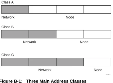
There are five standard classes of IP addresses. These address classes have different ways of determining the network and host sections of the address, allowing for different numbers of hosts on a network. Each address type begins with a unique bit pattern, which is used by the TCP/IP software to identify the address class. After the address class has been determined, the software can correctly identify the host section of the address. The follow figure shows the three main address classes, including network and host sections of the address for each address type.
NETGEAR Wireless Router Setup Manual
Network, Routing, and Firewall Basics B-3
Figure B-1: Three Main Address Classes
The five address classes are: • Class A
Class A addresses can have up to 16,777,214 hosts on a single network. They use an eight-bit network number and a 24-bit node number. Class A addresses are in this range:
1.x.x.x to 126.x.x.x.
• Class B
Class B addresses can have up to 65,354 hosts on a network. A Class B address uses a 16-bit network number and a 16-bit node number. Class B addresses are in this range:
128.1.x.x to 191.254.x.x.
• Class C
Class C addresses can have 254 hosts on a network. Class C addresses use 24 bits for the network address and eight bits for the node. They are in this range:
192.0.1.x to 223.255.254.x.
• Class D
Class D addresses are used for multicasts (messages sent to many hosts). Class D addresses are in this range:
224.0.0.0 to 239.255.255.255.
• Class E
Class E addresses are for experimental use.
7261
Class A
Network Node
Class B
Class C
Network Node
B-4 Network, Routing, and Firewall Basics
This addressing structure allows IP addresses to uniquely identify each physical network and each node on each physical network.
For each unique value of the network portion of the address, the base address of the range (host address of all zeros) is known as the network address and is not usually assigned to a host. Also, the top address of the range (host address of all ones) is not assigned, but is used as the broadcast address for simultaneously sending a packet to all hosts with the same network address.
Netmask
In each of the address classes previously described, the size of the two parts (network address and host address) is implied by the class. This partitioning scheme can also be expressed by a netmask associated with the IP address. A netmask is a 32-bit quantity that, when logically combined (using an AND operator) with an IP address, yields the network address. For instance, the netmasks for Class A, B, and C addresses are 255.0.0.0, 255.255.0.0, and 255.255.255.0, respectively.
For example, the address 192.168.170.237 is a Class C IP address whose network portion is the upper 24 bits. When combined (using an AND operator) with the Class C netmask, as shown here, only the network portion of the address remains:
11000000 10101000 10101010 11101101 (192.168.170.237)
combined with:
11111111 11111111 11111111 00000000 (255.255.255.0)
Equals:
11000000 10101000 10101010 00000000 (192.168.170.0)
As a shorter alternative to dotted-decimal notation, the netmask may also be expressed in terms of the number of ones from the left. This number is appended to the IP address, following a backward slash (/), as “/n.” In the example, the address could be written as 192.168.170.237/24, indicating that the netmask is 24 ones followed by 8 zeros.
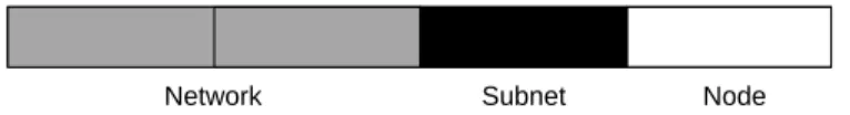
Subnet Addressing
By looking at the addressing structures, you can see that even with a Class C address, there are a large number of hosts per network. Such a structure is an inefficient use of addresses if each end of a routed link requires a different network number. It is unlikely that the smaller office LANs would have that many devices. You can resolve this problem by using a technique known as subnet addressing.
NETGEAR Wireless Router Setup Manual
Network, Routing, and Firewall Basics B-5
Subnet addressing allows us to split one IP network address into smaller multiple physical networks known as subnetworks. Some of the node numbers are used as a subnet number instead. A Class B address gives us 16 bits of node numbers translating to 64,000 nodes. Most
organizations do not use 64,000 nodes, so there are free bits that can be reassigned. Subnet addressing makes use of those bits that are free, as shown below.
Figure B-2: Example of Subnetting a Class B Address
A Class B address can be effectively translated into multiple Class C addresses. For example, the IP address of 172.16.0.0 is assigned, but node addresses are limited to 255 maximum, allowing eight extra bits to use as a subnet address. The IP address of 172.16.97.235 would be interpreted as IP network address 172.16, subnet number 97, and node number 235. In addition to extending the number of addresses available, subnet addressing provides other benefits. Subnet addressing allows a network manager to construct an address scheme for the network by using different subnets for other geographical locations in the network or for other departments in the organization.
Although the preceding example uses the entire third octet for a subnet address, note that you are not restricted to octet boundaries in subnetting. To create more network numbers, you need only shift some bits from the host address to the network address. For instance, to partition a Class C network number (192.68.135.0) into two, you shift one bit from the host address to the network address. The new netmask (or subnet mask) is 255.255.255.128. The first subnet has network number 192.68.135.0 with hosts 192.68.135.1 to 129.68.135.126, and the second subnet has network number 192.68.135.128 with hosts 192.68.135.129 to 192.68.135.254.
Note: The number 192.68.135.127 is not assigned because it is the broadcast address of the first subnet. The number 192.68.135.128 is not assigned because it is the network address of the second subnet.
7262
Class B
B-6 Network, Routing, and Firewall Basics
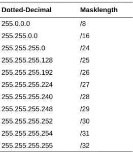
The following table lists the additional subnet mask bits in dotted-decimal notation. To use the table, write down the original class netmask and replace the 0 value octets with the dotted-decimal value of the additional subnet bits. For example, to partition your Class C network with subnet mask 255.255.255.0 into 16 subnets (4 bits), the new subnet mask becomes 255.255.255.240.
The following table displays several common netmask values in both the dotted-decimal and the masklength formats.
Configure all hosts on a LAN segment to use the same netmask for the following reasons: Table 6-1. Netmask Notation Translation Table for One Octet
Number of Bits Dotted-Decimal Value
1 128
2 192
3 224
4 240
5 248
6 252
7 254
8 255
Table 6-2. Netmask Formats Dotted-Decimal Masklength
255.0.0.0 /8
255.255.0.0 /16
255.255.255.0 /24
255.255.255.128 /25
255.255.255.192 /26
255.255.255.224 /27
255.255.255.240 /28
255.255.255.248 /29
255.255.255.252 /30
255.255.255.254 /31
NETGEAR Wireless Router Setup Manual
Network, Routing, and Firewall Basics B-7
• So that hosts recognize local IP broadcast packets
When a device broadcasts to its segment neighbors, it uses a destination address of the local network address with all ones for the host address. In order for this scheme to work, all devices on the segment must agree on which bits comprise the host address.
• So that a local router or bridge recognizes which addresses are local and which are remote
Private IP Addresses
If your local network is isolated from the Internet (for example, when using NAT), you can assign any IP addresses to the hosts without problems. However, the IANA has reserved the following three blocks of IP addresses specifically for private networks:
10.0.0.0 - 10.255.255.255 172.16.0.0 - 172.31.255.255 192.168.0.0 - 192.168.255.255
Choose your private network number from this range. The DHCP server of the wireless router is preconfigured to automatically assign private addresses.
Regardless of your particular situation, do not create an arbitrary IP address; always follow the guidelines explained here. For more information about address assignment, refer to RFC 1597,
Address Allocation for Private Internets, and RFC 1466, Guidelines for Management of IP Address Space. The Internet Engineering Task Force (IETF) publishes RFCs on its Web site at www.ietf.org.
Single IP Address Operation Using NAT
In the past, if multiple computers on a LAN needed to access the Internet simultaneously, you had to obtain a range of IP addresses from the ISP. This type of Internet account is more costly than a single-address account typically used by a single user with a modem, rather than a router. The wireless router employs an address-sharing method called Network Address Translation (NAT). This method allows several networked computers to share an Internet account using only a single IP address, which may be statically or dynamically assigned by your ISP.
The router accomplishes this address sharing by translating the internal LAN IP addresses to a single address that is globally unique on the Internet. The internal LAN IP addresses can be either private addresses or registered addresses. For more information about IP address translation, refer to RFC 1631, The IP Network Address Translator (NAT).
B-8 Network, Routing, and Firewall Basics
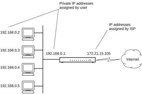
The following figure illustrates a single IP address operation.
Figure B-3: Single IP Address Operation Using NAT
This scheme offers the additional benefit of firewall-like protection because the internal LAN addresses are not available to the Internet through the translated connection. All incoming inquiries are filtered out by the router. This filtering can prevent intruders from probing your system. However, using port forwarding, you can allow one computer (for example, a Web server) on your local network to be accessible to outside users.
MAC Addresses and Address Resolution Protocol
An IP address alone cannot be used to deliver data from one LAN device to another. To send data between LAN devices, you must convert the IP address of the destination device to its media access control (MAC) address. Each device on an Ethernet network has a unique MAC address, which is a 48-bit number assigned to each device by the manufacturer. The technique that associates the IP address with a MAC address is known as address resolution. Internet Protocol uses the Address Resolution Protocol (ARP) to resolve MAC addresses.
7786EA
192.168.0.2
192.168.0.3
192.168.0.4
192.168.0.5
192.168.0.1 172.21.15.105 Private IP addresses
assigned by user
Internet IP addresses assigned by ISP
NETGEAR Wireless Router Setup Manual
Network, Routing, and Firewall Basics B-9
If a device sends data to another station on the network and the destination MAC address is not yet recorded, ARP is used. An ARP request is broadcast onto the network. All stations on the network receive and read the request. The destination IP address for the chosen station is included as part of the message so that only the station with this IP address responds to the ARP request. All other stations discard the request.
Related Documents
The station with the correct IP address responds with its own MAC address directly to the sending device. The receiving station provides the transmitting station with the required destination MAC address. The IP address data and MAC address data for each station are held in an ARP table. The next time data is sent, the address can be obtained from the address information in the table. For more information about address assignment, refer to the IETF documents RFC 1597, Address Allocation for Private Internets, and RFC 1466, Guidelines for Management of IP Address Space. For more information about IP address translation, refer to RFC 1631, The IP Network Address Translator (NAT).
Domain Name Server
Many of the resources on the Internet can be addressed by simple descriptive names such as www.NETGEAR.com. This addressing is very helpful at the application level, but the descriptive name must be translated to an IP address in order for a user to actually contact the resource. Just as a telephone directory maps names to phone numbers, or as an ARP table maps IP addresses to MAC addresses, a domain name system (DNS) server maps descriptive names of network resources to IP addresses.
When a computer accesses a resource by its descriptive name, it first contacts a DNS server to obtain the IP address of the resource. The computer sends the desired message using the IP address. Many large organizations, such as ISPs, maintain their own DNS servers and allow their customers to use the servers to look up addresses.