Configuration
Software Manual
Important Notice
This guide is delivered subject to the following conditions and restrictions:
This guide contains proprietary information belonging to RISCO Group. Such information is supplied solely for the purpose of assisting explicitly and properly authorized users of the system.
No part of its contents may be used for any other purpose, disclosed to any person or firm, or reproduced by any means, electronic or mechanical, without the express prior written permission of RISCO Group.
The information contained herein is for the purpose of illustration and reference only.
Information in this document is subject to change without notice.
Corporate and individual names and data used in examples herein belong to their respective owners.
No part of this document may be reproduced in any form without prior written permission from the publisher.
All rights reserved.
Configuration Software Manual
Page 3 Table of Contents
Chapter 1 - Getting Started ... 5
1.1 System Requirements ... 5
1.2 Hardware Setup ... 6
1.3 Installing the Configuration Software Program ... 8
1.4 Initializing the System Database ... 10
1.5 Using the Advanced Database Connection Utility ... 12
1.6 Setting the Software Language ... 13
1.7 Activating the Configuration Software from your Desktop ... 14
Chapter 2 - Your Screen ... 15
2.1 Main Menu ... 16
2.2 Tool Bar ... 16
2.3 Directory (Navigation Tree Map) ... 17
2.4 Client List ... 19
2.5 Connection Indication ... 19
2.6 Elapsed Time ... 19
2.7 Trouble Indication ... 19
2.8 Status Indication ... 19
2.9 Partition Indication ... 19
2.10 Main Screen ... 19
2.11 Path ... 19
Chapter 3 - Main Menu Options ... 20
3.1 Client ... 20
3.2 View ... 23
3.3 Communication ... 23
3.4 Tools ... 31
3.5 Help ... 35
Chapter 4 - Client Connection Settings ... 36
Chapter 5 - System Overview ... 37
Chapter 6 - System Configuration ... 38
6.1 System Screen ... 38
6.2 (Wireless) Devices ... 38
6.3 Codes ... 38
6.4 Communication ... 39
6.5 Monitoring Station ... 39
6.6 Configuration Software ... 39
6.7 Follow Me ... 39
Chapter 7 - Audio ... 40
Chapter 8 - Scheduler ... 41
Chapter 9 – (Radio Device) Allocation ... 43
9.1. Identification ... 43
9.3 Deleting Wireless Accessories ... 45
Chapter 10 - System Status ... 46
Chapter 11 – Diagnostic (Testing) ... 49
Chapter 12 - Event Log ... 50
Appendix A SQL Server Express 2005 Management ... 51
1 Adding Microsoft SQL Server 2005 Administrator Privileges to a User ... 52
2 Uninstalling RISCOGROUP instance on the Microsoft SQL Server 2005 ... 52
3 Uninstalling Microsoft SQL Server 2005 Common Components ... 54
4 Reinstalling Microsoft SQL Server 2005... 54
Appendix B Using the Advanced Database Connection Utility ... 55
Appendix C Configuration Software Upgrade ... 56
Configuration Software Manual
Page 5
Chapter 1 - Getting Started
This manual explains how to use the Configuration Software supporting RISCO Group's Flexible Wireless Solution. By using the Configuration Software, you can program the RISCO system from your own PC by selecting the features you require from the many described in this manual. You can customize the RISCO system in line with the special requirements of the client. This can be done at the client’s premises with a direct link to a laptop computer, or from a remote location via a phone connection using a modem, GSM or via IP.
Configuration Software also enables you to coordinate the activities of your users, as well as maintain records of both users’ activities and customized configurations through an on-line status display. You can receive data from the RISCO system to your computer to make changes when needed and then send data from your computer to the RISCO system with the new set up that you have prepared.
By using the Configuration Software, you can:
Manage your RISCO Group clients and their databases
Remotely monitor and update the status of every system device in real time.
Capture client settings for purposes of customization, backup and upgrade.1.1 System Requirements
Recommended minimum system requirements:
CPU P4 3GHz or AMD 3500+
RAM 2 GB Dual DDR 400 or above
Hard Disk SATA2 with 5 GB free space
Display PCI Express 256MB
Screen Resolution 1024 x 768
Network Ethernet port
1.2 Hardware Setup
Programming the RISCO wireless security system can be done: locally, remotely via modem or GSM, or via IP.
1.2.1 Local
The following diagram displays the local system connection:
To establish direct cable connection from your computer to the RISCO system: Connect the RS232 cable to your computer.
Connect the RS232 cable to the RS232 Communication Connector on the RISCO system.
Power up your computer and activate the Configuration software.
Set up the parameters for direct communication in the Configuration Software (see page 26).
Note: To enable local communication, set the Baud Rate to Set to 38400 (default value for Agility) or 115200 (default value for LightSYS)
1.2.2 Remote PSTN Connection
The following diagram displays the overall system connection to the PSTN network:
To establish remote PSTN connection from your PC to the RISCO system: 1. Connect the modem to your PC and telephone line according to the above
diagram.
2. Check the dial tone on your phone line.
3. After hearing the dial tone, hang up and power up your computer and modem and then activate the Configuration software.
RISCO system
RS232 Cable R
S 23 2 Comm . Conn ect or PC
PC GSM/PSTN
MODEM
PSTN TELEPHONE LINE (2400 bps)
RISCO system Mode m Modu le
Configuration Software Manual
Page 7
4. Set up the parameters for PSTN communication channel in the Configuration software (see page 27).
1.2.3 Remote GSM Connection
Remote Configuration can be performed using the GSM data channel if a GSM/GPRS module has been installed in the RISCO system.
The following diagram displays the overall system connection using a GSM network:
To establish remote GSM connection from your PC to the RISCO system:
1. Connect the GSM/PSTN modem to your computer. You can use a cellular phone as your computer modem.
2. Power up your computer and activate the Configuration software.
3. Set up the parameters for GSM communication channel in the Configuration software (see page 28).
1.2.4 TCP/IP Ethernet Connections
The following diagram displays the overall system connection between the security panel and IP network:
To establish IP network connection using the TCP/IP module:
1. Connect the RISCO system to the Ethernet by plugging an appropriate Ethernet cable plug into the RJ-45 connector on the IP module.
2. Power up your computer and activate the Configuration software. 3. Set up the parameters for IP communication channel in the Configuration
software (see page 29). IP NETWORK RISCO system IP Modu le PC
PC GSM/PSTN MODEM
GSM NETWORK (9600 bps) RISCO system GSM/ GPRS Modu le
1.2.5 Remote GPRS Connection
Remote Configuration can be performed using the GPRS data channel if a GSM/GPRS module has been installed in the RISCO system. By sending an SMS message
comprising of your Entry Host IP address and Entry Host Port number to the GSM/GPRS module in the RISCO system, the panel is able to connect to your PC. The following diagram displays the overall system connection between the RISCO system security panel using the GPRS module:
To establish GPRS connection:
1. Connect your computer to the IP network. 2. Connect the GPRS Module to the GSM network.
3. Power up your computer and activate the Configuration software.
4. Set up the parameters for GPRS communication channel in the Configuration software (see page 29 for more information).
5. Send an SMS to the device GSM phone number containing the necessary GPRS hosting information (see page 29 step 7).
1.3 Installing the Configuration Software Program
Notes:1. Before installing the Configuration Software Program make sure that Microsoft Framework 3.5 has been installed on the computer. If it has not been installed, go to the Configuration Software Installation CD, in the dotnetfx35 folder (and, x64 or x86 subfolder), run the dotnetfx setup application.
2. For Microsoft Windows Vista users only, the User Account Control (UAC) feature must be turned off. Go to Control PanelUser AccountsTurn User Account Control on or off. Uncheck the checkbox and click OK.
Configuration Software Manual
Page 9 Installing the Configuration software:
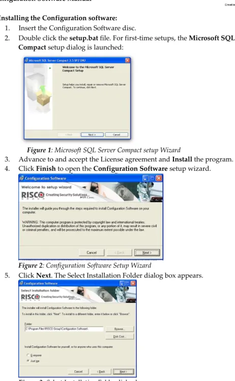
1. Insert the Configuration Software disc.
2. Double click the setup.bat file. For first-time setups, the Microsoft SQL Server Compact setup dialog is launched:
Figure 1: Microsoft SQL Server Compact setup Wizard
3. Advance to and accept the License agreement and Install the program. 4. Click Finish to open the Configuration Software setup wizard.
Figure 2: Configuration Software Setup Wizard
5. Click Next. The Select Installation Folder dialog box appears.
6. Select a location on your computer for the Installation folder. The default location is C:\Program Files\RISCO Group\Configuration software\.
7. Select either the Everyone or Just me option to determine who can use the program on your computer and click Next. The Confirmation dialog box appears.
Figure 4: Confirmation dialog box 8. Click Next to begin program installation. 9. Click Close when installation is complete.
1.4 Initializing the System Database
Initializing the system database:
1. Go to Start Programs RISCO Group Configuration Software System Organizer. After entering access credentials (default User Name: Admin, Password: 123) The System Organizer dialog appears:
Figure 5: System Organizer dialog
2. Select Database in the System Organizer navigation tree. (If your system requires support for multiple concurrent connections or enhanced performance, consider usage of SQL Server Express Edition 2005 (SQLSEE), as detailed in
Appendix A (which also details troubleshooting of any resulting problems arising thereof.) See
Appendix C for upgrading existing SQLSEE databases)Configuration Software Manual
Page 11
3. Click the Initialize button to display Figure 6: Database Initialize Complete. If this installation is an upgrade, the Database Initialize Options dialog box appears:
Figure 6: Database Initialize Options dialog
4. Click one of the following options:
a. Recreate Database – to remove the current database and recreate it with default values
b. Upgrade Database – to upgrade the current database to the required version c. Cancel – select Cancel for first time installation.
5. Click the Select button. When initialization has been successfully completed the status of each action should read as Succeed:
1.5 Using the Advanced Database Connection Utility
The Advanced Database Connection Utility is used to test the database parameters when initializing of the database has failed.
To test the database parameters:
1. In the System Organizer select Connection from the navigation tree. The following dialog box appears:
Figure 8: Connection dialog
2. Select the location of the desired database from the Database Location dropdown list.
3. Ensure the default Database Name displayed is: ConfigurationSoftware. 4. Enter the password as required: P@ssw0rd (default).
Note: When testing database parameters prior to initializing the system database (see step 1.4), the default user name will be sa and the default password will be Syn0p$Y$.
5. Enter a connection timeout amount for performing a test.
6. Click the button to check the connection to the database. When connection has been successful click the button.
Note: To save your database selection without testing, check the Save without testing checkbox and then click .
Configuration Software Manual
Page 13
1.6 Setting the Software Language
To set the software language:
1. In the System Organizer select Languages from the navigation tree. The following dialog box appears:
Figure 9: Languages dialog
2. Select the desired language from the Supported Languages dropdown list and click the Set Language button. The following message appears:
Figure 10: Languages message dialog
1.7 Activating the Configuration Software from your Desktop
Logging in to the Configuration software:
1. Double-click the Configuration Software icon on your desktop to run the program. The Configuration Software login dialog box appears:
Figure 11: Configuration S/W login dialog
2. Enter your user name. The default user name is Admin. 3. Enter your password. The default password is 123.
Note: When entering your user name and password an orange line appears under the field which indicates the number of letters/digits you have entered. The line will stop at the maximum number to indicate that you are unable to enter further letters/digits.
1. Click the Login button to activate the program. If this is an initial system installation, Figure 14: Client dialog box: Personal Information tab, page 20 appears. Note: If you have previously defined only one client in the software, the program will open this client automatically. If you have more than one client, the program opens a Find Client dialog box with a list of all the clients. Select the relevant client from the list.
Note: Configuration Software enables activation of an optional DEBUG window. To enable the DEBUG window option:
1. Open the following file for editing:
C:\Program Files\RISCO Group\Configuration Software\CS.exe.config.
2. Change the <value> of the “DEBUG” setting from False to True.
Configuration Software Manual
Page 15
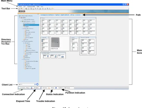
Chapter 2 - Your Screen
The configuration software window is divided into the following sections: Main Menu
Tool Bar
Directory (Navigation Tree Map) Client List
Connection Indication Elapsed Time
Trouble Indication Status Indication Partition Indication Main Screen Path
2.1 Main Menu
The Main Menu is divided into 4 sub-menus that include various system programming operations. For more information on each sub-menu refer to:
Client – page 20 View – page 23
Communication – page 23 Tools – page 31
Help – page 35
2.2 Tool Bar
The icons in the toolbar provide quick access to certain operations that are found in the Main Menu.
Icon Description
/ Open/Close Navigation Tree (see page 18) New Client (see page 20)
Find Client (see page 22) Refresh (see page 22)
View Previous Screen (see page 22) Save Client (see page 22)
Save Current Screen (see page 22) Send Current Screen (see page 23) Receive Current Screen (see page 24)
Restore Defaults To Current Screen (see page 24) Verify Screen (see page 24)
Report Screen (see page 34) Capture Screen (see page 34) Load Screen (see page 34)
Connect: Direct / GSM/Modem / TCP/IP / GPRS (see page 36) Note: Where available,
Agility User Manual
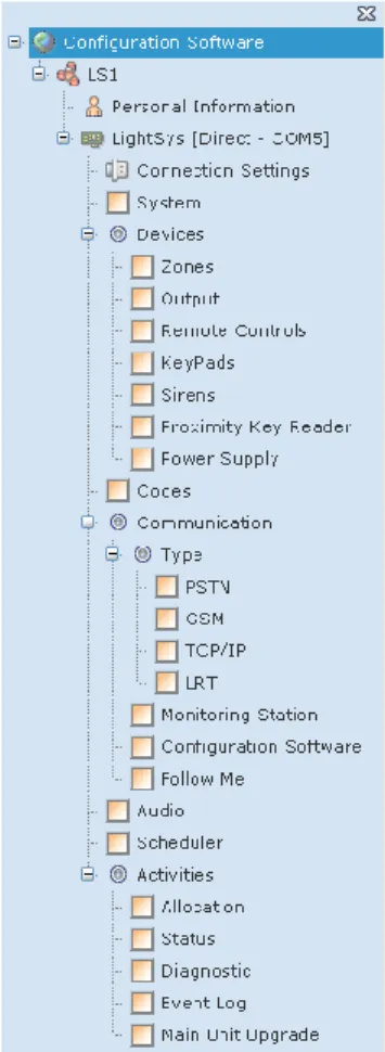
2.3 Directory (Navigation Tree Map)
The directory appears as a hierarchical list that contains the client's main configuration features and enables you to easily navigate between the different screens. The list is divided as follows:
Figure 13: Directory (Navigation Tree Map) For more information on each feature refer to:
New Client – page 20
Connection Settings – page 36 Overview – page 37
System – page 38
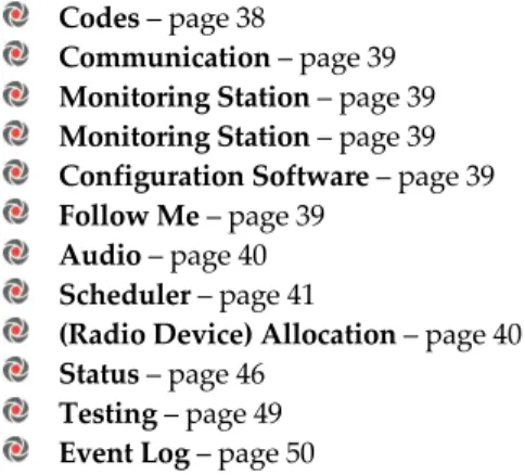
Codes – page 38
Communication – page 39 Monitoring Station – page 39 Monitoring Station – page 39 Configuration Software – page 39 Follow Me – page 39
Audio – page 40 Scheduler – page 41
(Radio Device) Allocation – page 40 Status – page 46
Testing – page 49 Event Log – page 50
To select a feature from the directory:
Click the feature you want to configure. The checkbox next to that feature becomes . The screen belonging to the selected feature will appear in the Main Screen with its path at the top. You can now configure the parameters of the feature you have selected.
Figure 14: Selecting a feature from the directory To show the directory:
1. Click the icon. -or-
2. From the main menu select View>Explorer Tree. To hide the directory:
Configuration Software Manual
Page 19 1. Click the icon.
-or-
2. From the main menu deselect View>Explorer Tree. -or-
3. Click the X at the top of the directory.
2.4 Client List
The Client List provides quick access to all of your clients and enables you to easily navigate between them.
To navigate between your clients:
1. Select a client from the drop down list.
2. Press . The navigation tree will provide a list of the selected client's screens. Note: If you have not checked the Load Client After Create check box when first creating the client (see page
20), the client will not appear on the navigation tree map.
2.5 Connection Indication
Indicates whether Communication connection has been established:
Red = No connection
Orange = Connecting
Green = Connected2.6 Elapsed Time
Indicates the amount of time you have been connected.
2.7 Trouble Indication
Indicates whether a trouble is present in the system.
2.8 Status Indication
Indicates the severest status present in the system.
2.9 Partition Indication
Indicates the severest status present in any of the partitions in the system.
2.10 Main Screen
Once you have selected a configuration feature from the directory it will appear in the Main Screen containing all the system's parameters relating to that feature for you to configure.
2.11 Path
Chapter 3 - Main Menu Options
3.1 Client
3.1.1 New Client To create a new client:
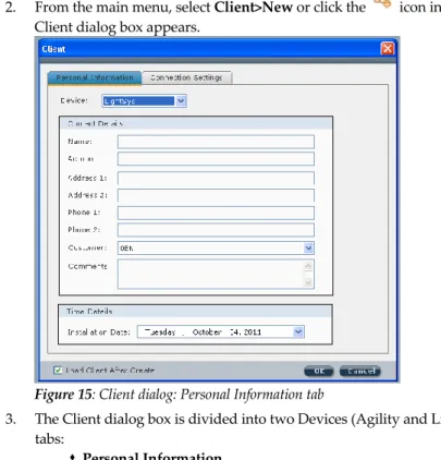
2. From the main menu, select Client>New or click the icon in the tool bar. The Client dialog box appears.
Figure 15: Client dialog: Personal Information tab
3. The Client dialog box is divided into two Devices (Agility and LightSYS) and two tabs:
Personal Information
Connection SettingsSelect the relevant device and in the Personal Information tab, enter the client's contact information (Figure 14).
Note: It is mandatory to fill in the Name field. Any mandatory fields that have not been filled or have been filled with invalid data will appear in yellow.
4. Select the relevant customer ID from the Customer drop down list. The
configuration software will upload the relevant default values and default labels for that customer ID to the new client.
Configuration Software Manual
Page 21
Note: If the selected Customer ID settings differ from that of the panel to which it connects, a Mismatch information pop-up is displayed upon each device connection attempt.
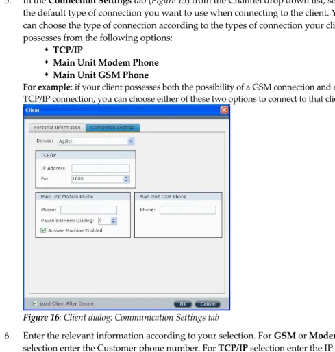
5. In the Connection Settings tab (Figure 15) from the Channel drop down list, select the default type of connection you want to use when connecting to the client. You can choose the type of connection according to the types of connection your client possesses from the following options:
TCP/IP
Main Unit Modem Phone
Main Unit GSM PhoneFor example: if your client possesses both the possibility of a GSM connection and a TCP/IP connection, you can choose either of these two options to connect to that client.
Figure 16: Client dialog: Communication Settings tab
6. Enter the relevant information according to your selection. For GSM or Modem selection enter the Customer phone number. For TCP/IP selection enter the IP address and port.
Note: You must define the port in the communication configuration before selecting it here. See page 26 for more information.
7. Check the Load Client After Create checkbox in order for it to appear in the client list as well as the directory. If you have not checked this checkbox you will not be able to view this client in the directory.
Note: The type of connection you have chosen to use appears next to RISCO system in the directory. For example:
3.1.2 Find
To find a client in the database:
1. From the main menu select Client>Find Client, or from the tool bar, click the Find Client icon. The Client Selection dialog box appears containing a list of all the clients and their personal information.
2. Click the relevant client from the list and click the Select button. The directory of that client appears on your screen.
3.1.3 Refresh
From the main menu select Client>Refresh, or from the tool bar, click to refresh the data on the screen to that of the client's last stored database.
3.1.4 Close
From the main menu, select Client>close to exit the current client. 3.1.5 Remove
From the main menu select Client>Remove to remove the current client from the database. 3.1.6 View Previous Screen
From the main menu select Client>View Previous Screen, or from the tool bar, click to return to the previous screen.
3.1.7 Save Current Screen
From the main menu select Client>Save Current Screen, or from the tool bar, click to save the currently displayed screen.
3.1.8 Save
Used to save changes made to the client. From the main menu select Client>Save, or from the tool bar, click the Save icon. The software will run through all the screens to check for incomplete data. "Not validated" will appear for a screen with an incomplete red field (red fields are mandatory to fill in). When all screens have been validated, the client data is saved and stored in the database.
Configuration Software Manual
Page 23
3.1.9 Save as…
From the main menu select Client>Save as… to save a copy of the client in the database. Rename this copy in order to use it as a new client.
3.1.10 Backup
From the main menu select Client>Backup>Export to export a client's information to backup files.
From the main menu select Client>Backup>Import to import the client's previously saved backup files.
3.1.11 Logout
From the main menu select Client>Logout to log out of the Configuration software. 3.1.12 Exit
From the main menu, select Client>Exit to exit the program.
3.2 View
From the main menu, select View>Explorer Tree to open/close the directory (navigation tree map) or from the tool bar click the icon.
3.3 Communication
The Communication menu is used for communication to and from the RISCO system. 3.3.1 Send
When online, you can send the screens' parameters from the Configuration software. To send data from the currently displayed screen to the RISCO system:
From the main menu, select Communication>Send>Screen, or from the tool bar, click the Send Current Screen icon.
To send data from all the screens to the RISCO system: From the main menu, select Communication>Send>All. To send data from specific screens to the RISCO system:
1. From the main menu, select Communication>Send>Selection.
2. Check the relevant screens from the Screens Selection dialog box that appears and then click OK.
-or-
3.3.2 Receive
When online, you can transmit information from the RISCO system to the Configuration software.
To receive data for the currently displayed screen from the RISCO system:
From the main menu, select Communication>Receive>Screen, or from the tool bar, click the Receive Current Screen icon.
To receive data for all the screens from the RISCO system: From the main menu, select Communication>Receive>All. To receive data for specific screens from the RISCO system:
1. From the main menu, select Communication>Receive>Selection.
2. Check the relevant screens from the Screens Selection dialog box that appears and then click OK.
-or-
Right click from within the tabular data cell and click Receive 3.3.3 Restore Defaults
Used to restore factory defaults.
To restore default values to the current screen:
From the main menu, select Communication>Restore Defaults>Screen, or from the tool bar, click .
To restore default values to all screens:
From the main menu, select Communication>Restore Defaults>All. To restore default values to specific screens simultaneously:
1. From the main menu, select Communication>Restore Defaults>Selection. 2. Check the relevant screens and click OK.
3.3.4 Verify
To verify that the data in the Configuration software is identical to the data in the RISCO system, proceed as follows:
1. When online, from the main menu select Communication>Verify and select the relevant option:
Screen – verifies the current screen (use the icon as a shortcut for this operation)
Configuration Software Manual
Page 25
Selection – verifies selected screens. A dialog box appears with a list of all the screens, check the relevant checkboxes and click OK.
2. When verification is complete the Compare Verify Viewer dialog box appears:
Figure 17: Compare Verify Viewer dialog box
The dialog box displays a directory of all the inconsistent parameters as well as three columns comparing the differences found between the Configuration software values, RISCO system values and Default values.
3. To accept a certain value right click the relevant line and select one of the following options (see figure below):
Leave Screen Values
Apply Device Changes (RISCO system values) Restore Default Changes
Notes:
1. To accept all changes made to the client right click the Client name.
2. To accept all changes under a specific branch, right click the relevant branch. For example: To accept the changes made to the Quick Arm and Allow Bypass parameters (see figure above), right click Controls.
The Compare Verify Viewer dialog box closes as soon as there are no inconsistencies left.
1. After verification is complete, right click the button to select the type of file you would like to save the report as from the following options: HTML, Text or CSV.
2. Click the button to export the file. 3.3.5 Connect/Disconnect
To establish communication with the RISCO system, from the main menu select Communication>Connect.
To disconnect communication with the RISCO system, from the main menu select Communication>Disconnect.
3.3.6 Configuration
This dialog box enables you to define the parameters of setting up the communication between the Configuration Software local installation and the RISCO system through direct cable, GSM, modem, TCP/IP, GPRS or SMS. Your system should be set correctly in order to connect to the RISCO system. Once defined, these configurations will be used by your computer, when trying to establish communication to any RISCO system panel. Direct communication
To define direct communication, set up the parameters as follows:
1. Select the Direct communication channel from the drop down list and fill in the parameters as follows:
Port: Select the relevant port
Baud Rate: Set to 38400 (default value for Agility) or 115200 (default value for LightSYS) Data Bits: Set to 8 (default value)
Parity: Set to None (default value) Stop Bit: Set to 2 (default value) Handshake: Set to None (default value)
Configuration Software Manual
Page 27 Figure 18: Local connection set up
2. In the Configurtion Software node, right-pane Security area, ensure that the Remote ID Code value is set to 0001 (standard encryption).
3. Click OK.
Remote PSTN communication
To define remote PSTN communication, set up the parameters as follows:
1. Select the Modem communication channel from the drop down list and fill in the parameters as follows:
Port: Select the relevant port
Baud Rate: Set to 2400 (default value) Data Bits: Set to 8 (default value) Parity: Set to None (default value) Stop Bit: Set to 1 (default value) Handshake: Set to None (default value)
Modem: Select the relevant Modem from the Modem dropdown list Callback Phone: Enter the callback telephone number
Figure 19: Remote PSTN connection set up 2. Click OK.
Remote GSM communication
To define Remote GSM communication, set up the parameters as follows: 1. Select the GSM communication channel from the drop down list and fill in the
parameters as follows: Port: Select the relevant port
Baud Rate: Set to 9600 (default value) Data Bits: Set to 8 (default value) Parity: Set to None (default value) Stop Bit: Set to 1 (default value) Handshake: Set to None (default value) Modem: Select GSM auto speed
Configuration Software Manual
Page 29 Figure 20: Remote GSM connection set up 2. Click OK.
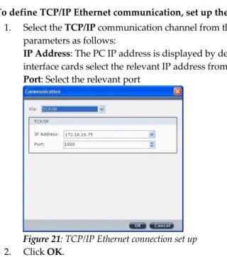
TCP/IP Ethernet communication
To define TCP/IP Ethernet communication, set up the parameters as follows: 1. Select the TCP/IP communication channel from the drop down list and fill in the
parameters as follows:
IP Address: The PC IP address is displayed by default. In the case of two network interface cards select the relevant IP address from the drop down list
Port: Select the relevant port
Figure 21: TCP/IP Ethernet connection set up 2. Click OK.
Remote GPRS communication
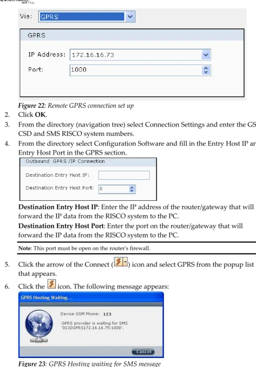
To define Remote GPRS communication, set up the parameters as follows: 1. Select the GPRS communication channel from the drop down list and fill in the
parameters as follows:
IP Address: The PC IP address is displayed by default. In the case of two network interface cards select the relevant IP address from the drop down list.
Port: Select the port on your PC that the router will forward the RISCO system data to.
Figure 22: Remote GPRS connection set up 2. Click OK.
3. From the directory (navigation tree) select Connection Settings and enter the GSM CSD and SMS RISCO system numbers.
4. From the directory select Configuration Software and fill in the Entry Host IP and Entry Host Port in the GPRS section.
Destination Entry Host IP: Enter the IP address of the router/gateway that will forward the IP data from the RISCO system to the PC.
Destination Entry Host Port: Enter the port on the router/gateway that will forward the IP data from the RISCO system to the PC.
Note: This port must be open on the router's firewall.
5. Click the arrow of the Connect ( ) icon and select GPRS from the popup list that appears.
6. Click the icon. The following message appears:
Configuration Software Manual
Page 31
The message is compiled of the following: installer code, the word GPRS, Entry Host IP, Entry Host Port.
7. Send an SMS to the device GSM phone number (defined in step 3) with the message that appears, for example: 0132GPRS172.16.16.75:1000
The RISCO system will respond to the communication request based on the information in the SMS.
Remote SMS communication
Define here the port which is to serve as the gateway to establish GPRS communication with the monitoring stations.
3.4 Tools
3.4.1 Authorization
Each person who is authorized to use the Configuration software should be registered as a user within the software. Each user is assigned a password that he uses when he activates the software. When you activate the Configuration software for the first time, you use the default password (123). You can have up to 50 users.
Access to the users list can be denied to all users except for the default user (administrator) who is listed as no.1 in the user list.
To ensure that only you or authorized personnel have access to your system it is necessary to change the default password, and establish passwords for your users. This is important as the same default is provided on all new software.
To add a new user to the list of your software's authorized users:
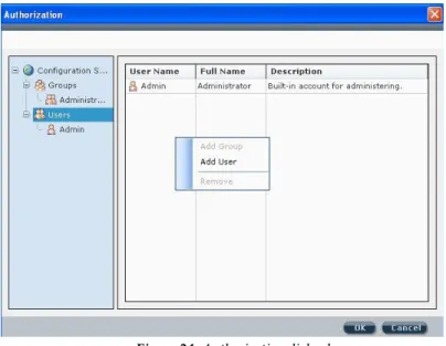
1. From the main menu select Tools>Authorization. The Authorization dialog box appears.
Figure 24: Authorization dialog box
3. Right click in the authorization dialog box and select Add User. The New User dialog box appears:
Figure 25: New User dialog box
4. Enter the relevant information and click OK. To remove a user from the authorization list:
Click a user from the list and then right click in the Authorization dialog box and select Remove.
Configuration Software Manual
Page 33 To add a new group to the authorization directory:
1. Select Groups from the Authorization directory and then right click in the Authorization dialog box and select Add Group. The New Group dialog box appears:
Figure 26: New Group dialog box
2. Enter a name and description for this group and click the Access Rights… button to define user rights for this group. The Access Rights dialog box appears:
Figure 27: Access Rights dialog box
3. Define this group's user rights according to the parameters in each of the 5 tabs: Operation, Connect, Data Transfer, User and Screens.
4. Click OK to return to the New Group dialog box.
5. Click OK to return to the Authorization dialog box. The new group appears in the list.
Report
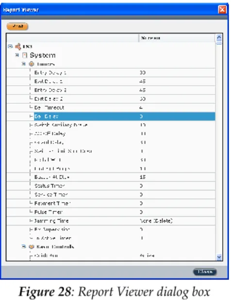
To generate reports go to Tools>Reports and select the relevant option: Screen/All/Selection. The Report Viewer appears with the generated report:
Figure 28: Report Viewer dialog box
The report displays the parameters of the selected screens as well as the advanced parameters of these screens.
To print the report, click the button. 3.4.2 Screen
If technical support is needed it is possible to send an image of a particular screen to the customer support team. The customer support team can then load the screen, as well as all the background data concerning that screen, and provide technical support.
To capture a screen:
From the main menu select Tools > Screen > Capture or from the tool bar click to capture an image of the screen and send it to customer support together with the relevant data regarding that screen.
To load a screen (for the customer support team):
From the main menu select Tools>Screen>Load or from the tool bar click to display the image of the captured screen and its data.
Configuration Software Manual
Page 35 3.4.3 Audit
Used to store a list of user actions. To execute an audit trail:
1. From the main menu select Tools>Audit. The Audit Trail dialog box appears:
Figure 29: Audit Trail dialog box
2. Click the button to filter the audit trail according to time span, users, actions and machines and click OK after each selection.
3. Click the button to execute the audit trail.
4. To export the results, right click the button to select the type of file you would like to save the audit as from the following options: HTML, Text or CSV.
5. Click the button to export the file.
3.5 Help
3.5.1 About
Chapter 4 - Client Connection Settings
Define here the RISCO system panel settings. To enter your client's connection information:
1. In the Connection Settings screen (see Figure 29) enter the relevant connection information according to the types of connection your client possesses:
TCP/IP Address and Port
GSM
ModemFor example: if your client possesses both the possibility of a GSM connection and a Modem connection, enter the client's GSM phone number and the client's Modem phone.
2. You can modify the default connection from the default drop down list. You may choose another connection option each time you want to connect to this client by clicking on the icon in the tool bar and selecting the type of connection you want to use.
Note: The type of connection you have chosen to use appears next to RISCO system in the directory. For example:
Configuration Software Manual
Page 37
Chapter 5 - System Overview
The Overview feature provides an overview of the client's system. The screen displays the following:
All the accessories (zones, remote controls, keypads, sirens, I/O modules) connected to the client's system and their diagnostics.
To view the diagnostic information, stand above the relevant icon, a pop-up box appears with information such as the accessory's name, serial number and assigned partition number.
The connection types available to the client's system in the communication section. The icon displays the RSSI signal intensity level.
Note: This screen does not display any status information. For status information, go to the Status screen (see page 46).
Chapter 6 - System Configuration
Note: To send a configuration to the RISCO system, receive a configuration from the RISCO system or restore default values, right click the relevant parameter and select the preferred option.
6.1 System Screen
System parameters can be configured in the System screen.
In the Timers area, enter the preferred value. To display the value range tool tip, hover the cursor above the relevant parameter's dropdown list.
In the Controls area, check the preferred checkboxes. For additional configuration
options, click the button.
6.2 (Wireless) Devices
RISCO system (wireless) accessories can be configured via the Configuration software in the following screens: Zones, Remote Controls (Key fobs), Keypads, Sirens, I/O Expander for Agility and Zones, Output, Remote Controls (Key fobs), Keypads, Sirens, Proximity Key Readers and Power Supply for LightSYS
The Label column displays the kind of device, for example: zone, siren, etc.
When a device has defined in the system supports additional parameters, right click the relevant line and select the enabled option Additional…
To change a value, double click the relevant field in the relevant line and select an option from the dropdown list that appears. For example in the Zones screen, to change the value in the Sound (at Arm) column, double click in the sound field for the relevant zone and select an option from the dropdown list.
Note: The Serial Code column is Read Only, to add a device to the system go to the Radio Device Allocation screen while online.
6.3 Codes
The Codes screen displays a list of the authority level and code for each user in the system as well as the partition each user has access to, the user's proximity tag number and whether or not the user is authorized with the Parent Control feature.
To change the authority level of a user, double click the Authority Level field in the relevant user's line and select an option from the dropdown list that appears: Master/User/Arm Only/Cleaner/Duress (for Agility)
UO Controller/Master/User/Armer/Maid/Un-Bypass/Guard/Duress (for LightSYS) To change or add a partition, click the relevant partition number.
Enter a proximity tag number for a user by double clicking in the Proximity Tag field and inputting the relevant number.
Configuration Software Manual
Page 39
6.4 Communication
Configure the client parameters for each communication type in the relevant screen: PSTN / GSM / TCP/IP/LRT (LightSYS only).
6.5 Monitoring Station
Configure the Monitoring station parameters in this screen. To view the lists of the Report Codes, click the button.
Note: Report codes can only be edited via the Configuration Software. To do so, click the
button to enter the Report Codes lists. Double click the relevant Event or Restore code field and enter the desired code.
For a detailed list of all available report codes refer to relevant RISCO system Report Code appendix.
6.6 Configuration Software
The Configuration Software screen allows the following configurations:
Configure the security codes for the configuration software. When establishing a code, note that an orange line appears under the field which indicates the maximum number of letters/digits you may enter.
Enter phone numbers for the call back feature. Enter the IP connection port.
6.7 Follow Me
Configure the Follow Me parameters in this screen
To enter a label or phone number/email address, double click the relevant line and field and input the information.
To change a value in the Type or Channel columns, double click the relevant field in the relevant line and select an option from the dropdown list that appears.
To enable Remote Listen and Remote Program features for a Follow Me number check the relevant checkbox.
To select which events will be reported to a specific Follow Me number go to the Events tab and select the relevant event Category. Check the preferred checkboxes in the index number column of the relevant Follow Me number.
For more information regarding how to configure the System, Wireless Devices, Codes, Communication, Audio parameters and User Activities refer to the relevant RISCO system Installer Manual.
Chapter 7 - Audio
Define voice message parameters in the Audio screen which is divided into the following sections:
Audio Messages - A voice message can be assigned to a zone, partition, output or macro. When an event occurs this voice message will be heard accordingly. To assign a word from the voice messages library, double click the relevant message number and line and select the desired word from the dropdown list (see Figure 31).
Local Message - Upon event occurrence, the system can announce the security situation to occupants of the premises by sounding a local announcement message. This announcement message can be enabled or disabled, per event. Enable a message announcement by checking the relevant checkbox.
Configuration Software Manual
Page 41
Chapter 8 - Scheduler
Up to 8 weekly programs (schedules) can be pre-defined in the system during which the system automatically arms/disarms or activates utility outputs.
Figure 33: Scheduler screen To pre-define a schedule:
1. From the directory (navigation tree map) select Scheduler. 2. The scheduler screen is divided into 2 sections:
Scheduler: select the schedule by clicking on the relevant line. Double click in the label column to enter a label. Double click in the type column to select the type of operation: Arm/Disarm or Utility Output. Check the enable checkbox if you want to cancel the schedule without deleting it from the software.
Parameters: Define up to two Start times and two Stop times for each day of the week of each schedule in the parameters section by double clicking on the relevant field and entering the desired times. Select the relevant partition by checking the partition checkbox.
The vacation program allows the system to ignore the pre-programmed schedules on the defined vacation days.
To pre-define vacations:
1. Click the button. The following dialog box appears:
Figure 34: Vacations dialog box
Configuration Software Manual
Page 43
Chapter 9
–
(Radio Device) Allocation
The following chapter describes:How to identify a wireless device
How to allocate a wireless device to the system via the Configuration software in order to later configure each device's parameters
Note: For more information on the different ways to allocate your devices to the system refer to the relevant RISCO system Installer Manual.
How to delete a wireless device from the system
Note: All the following actions can be performed only when online. Establish communication between the main unit and the Configuration software by selecting Communication > Connect from the main menu.
9.1. Identification
9.1.1 (In Agility) To identify a wireless device
Open the Radio Device Allocation screen. In the Identification area, click and then activate the device.
Note: When performing identification, the system recognizes the device but does not perform allocation. 9.1.2 (In LightSYS)
For Bus Devices, filter the eligible devices set via the drop-down listing (Bus Scan; Look for New Devices; Full Auto Install; Allocated AND Connected; or Allocated OR Connected) and then click to display the set of allocated/connected bus devices and an Action (delete or allocate) column. Press to perform the desired action.
9.2 Adding System Devices
9. 2.1 Wireless
To perform Remote Learning (Allocation)
1. From the Activities > (Radio Device) Allocation tree node, in LightSYS, click the right-pane Wireless Devicetab .
2. Allocation is performed either by assigning the device serial number to the RISCO system or through RF allocation. If by serial number, enter it in the Allocation > Serial code input box.
Note: The serial number can be found on the device itself and on its packaging. The first 3 numbers represent the category that the device belongs to (for example: detectors, sirens, keypads, remote controls etc.).
The following 8 numbers represent the device's unique serial ID number.
3. In Agility, if Automatic is selected from the Indexed dropdown list, the system will automatically assign the next available index number.
4. Click the button in Agility or in LightSYS to allocate the specified Accessory Type serial code. If RF allocation is to performed, this operation will set the main unit to Learn mode. The following message appears:
5. Send a transmission from the device. (See table below)
How to send a write message (transmission):
Wireless Device Sending Write Message
Detector/Contacts Press the tamper switch for 3 seconds *2-Way Keypad Press both [Away/Full Arm] and
[Stay/Part Arm] keys simultaneously for at least 2 seconds
1-Way Keypad Press the [Arm] key twice
1-Way Key fob Press the button for at least 2 seconds *2-Way Remote
Control
Press both [Away/Full Arm] and and [Stay/Part Arm]keys simultaneously for at least 2 seconds
Smoke Detector Insert battery. Write message is send automatically within 10 seconds. *Siren Press the reset switch on the siren, wait
2 sec. and then close the tamper switch Gas, CO detectors Press the test button for 3 seconds 2 Panic Button Key fob Press both buttons for at least 7 seconds *Agility only
6. The main unit will acknowledge the transmission with a sound. When the system recognizes the device the Radio Device Allocation screen indicates that the status of allocation has been successful.
Configuration Software Manual
Page 45 9. 2.2 Bus Devices (In LightSYS)
To perform Remote Learning (Allocation)
1. From the Activities > Allocation tree node, click the right-pane Bus Devicetab. 2. Use the Manual Allocation to virtually allocate indexed accessories.
9.3 Deleting Wireless Accessories
To delete a wireless accessory from the system:
1. In the Radio Device Allocation screen in the Delete RF Device area enter the device's serial code.
2. Click the button.
To delete all the wireless accessories from the system: 1. Click the button.
2. When all accessories have been deleted the screen will indicate that deletion has been successful.
(In LightSYS)
To delete a Bus Device from the system:
1. For devices connected as per the Scan Devices table (9.1.1.2 above), click the Action column entry for the device to be deleted and select Delete from the drop-down entry list.
Chapter 10 - System Status
You can view the status of your system via the Status screen which displays any trouble on the main panel and information regarding the status of each zone, partition, expander and output.
The Status screen also enables you to send commands to each partition and zone. Changes initiated in this screen are immediately transmitted and reflected in the system settings display.
Configuration Software Manual
Page 47 The Status screen is divided into the following sections:
Zones – You can view the status of all the zones in your system. Each zone in use is color coded according to its state:
Note: To view the color code key on your screen, click the button. To view the diagnostic information of a zone stand above the
relevant icon, a pop-up box appears with information such as the accessory's name, status, serial number and assigned partition number.
(Agility) Expanders (I/O Wired Zones) – if you have defined zones 33 to 36 in your system, you can view their status according to the color coded key. Partitions – This section displays the Partitions status.
Click a partition to view which zones are assigned to that partition. The number of the zone assigned to the selected partition will be
highlighted:
You can arm/disarm a partition that is in Ready mode, right click the relevant partition with your mouse and select Arm. To arm/disarm all the partitions in the system select Arm All/Disarm All.
Outputs – This section displays the outputs' status (activated or deactivated). To activate/deactivate the output, right click the relevant output with your mouse and select Activate/Deactivate.
Actions — Click the active button bars to alter existing parameter settings, as needed.
Clock – This section displays the RISCO system's time. To change the RISCO system's time to your computer's time, click the Set Clock button.
Note: The status screen does not display the status (Open/Closed) of those U/O's that have been defined as latched.
Configuration Software Manual
Page 49
Chapter 11
–
Diagnostic (Testing)
The Diagnostic (Testing) screen displays the RSSI signal intensity levels, battery charging levels and versions of the RISCO system and accessories. You can perform a diagnostic test for the RSSI level on the following: main unit, zones, bus and wireless devices, and communication and I/O modules.
To perform a diagnostic test, firstly establish communication between the main unit and the Configuration software by selecting Communication>Connect from the main menu and then click the button.
(In Agility) to perform a diagnostic test sequentially for the main unit and all the accessories, click the . A test for the main unit and each accessory will run in sequence.
Note: The RSSI level will appear from 0 – 100% in the Noise/Communication level bar.
Chapter 12 - Event Log
The Configuration Software keeps a record of all events that have occurred in the system. This record is the Event Log.
To view all of the events that have occurred in the system:
1. From the directory, select User Activities>Event Log to open the Event Log screen.
2. Select the order (ascending/descending) the events will appear in, from the Order By dropdown list.
3. Click the button. A list of all the events appears. The list can contain up to 255 events.
Figure 37: Event Log Screen
To view events that have occurred from a specific date and time:
1. From the directory, select Activities>Event Log to open the Event Log screen. 2. Enter the desired date and time in the Filter field and click . A list of the
events that have occurred from the chosen date and time appears.
Note: The events appear in the following order: from the earliest to the latest event, the most recent event will appear as the last event on the list.
To export the Event Log to your computer:
1. After viewing an event log, click the button and choose a type of file from the list: HTML, Text or CVS file. The Save As dialog box appears. 2. Select a destination and enter a name for the file and click Save.
Configuration Software Manual
Page 51
Appendix A
SQL Server Express 2005 Management
Use the non-default SQL Server Express 2005 (SQLSE) database if your system requires support for multiple concurrent connections or enhanced performance or if the present installation is an upgrade of an existing SQLSE installation.This appendix documents SQLSE installation and upgrade procedures and troubleshooting of possible complications.
To initialize and install the SQL Express edition database:
1. In the Programs > RISCO Group > Configuration Software > System Organizer window, Install SQL Engine tree-node option, click as per the following:
2. Upon successful instance creation, the message Installation status: RISCOGROUP instance exists is displayed.
3. Click the Database tree node option and the (browse) button to display the Select Database dialog in which you SqlExpressEdition, as per the following:
If the Microsoft SQL Server 2005 has failed to install the different procedures that can be performed:
Adding Microsoft SQL Server 2005 Administrator Privileges to a User Uninstalling RISCOGROUP instance on the Microsoft SQL Server 2005 Uninstalling Microsoft SQL Server 2005 Common Components
1 Adding Microsoft SQL Server 2005 Administrator Privileges to a
User
If Microsoft SQL Server 2005 fails to install, it is possible that the logged on user may not have Administrator privileges to the Microsoft SQL Server 2005.
To add Microsoft SQL Server 2005 Administrator privileges to a user: For XP OS:
1. Go to Start Programs Microsoft SQL Server 2005 Configuration Tools SQL Server Surface Area Configuration.
2. Click on the Add New Administrator link. The name of the currently logged on user in the top right of the window appears.
3. Click on the button to move the left box contents over to the right box and then click OK. The currently logged on user now has Administration privileges to the SQL Server 2005.
For Win 7 OS:
1. Right-click the CS desktop icon and select Properties
2. In the Compatibility tab, select the Privilege Level Run this program as an administrator checkbox.
Note: If Microsoft SQL Express 2005 SP2 continues to fail to install, please contact customer support services.
2 Uninstalling RISCOGROUP instance on the Microsoft SQL Server
2005
If Microsoft SQL Server 2005 fails to install, try to uninstall the RISCOGROUP instance on the Microsoft SQL Server 2005.
Notes:
1. Do not uninstall the RISCOGROUP instance if you have other RISCO Group software programs installed on your computer.
Configuration Software Manual
Page 53
2. All existing clients will be deleted when uninstalling the RISCOGROUP instance on the Microsoft SQL Server 2005.
Before removing the RISCOGROUP instance on the Microsoft SQL Server 2005 back up all existing databases.
To uninstall the RISCOGROUP instance on the Microsoft SQL Server 2005: 1. For Windows XP: Go to Start Settings Control Panel Add/Remove
Programs.
For Windows Vista: Go to Start Settings Control Panel Program and Features.
2. Double click on Microsoft SQL Server 2005. The Component Selection dialog box appears:
3. Select RISCOGROUP: Database Engine and click Next.
4. When uninstall is complete, go to: My Computer C Program Files Microsoft SQL Server MSSQL.x MSSQL Data.
Note: There may be several MSSQL.x folders on your computer. If so, you need to check in which of these folders the MSSQL Data folders appear.
3 Uninstalling Microsoft SQL Server 2005 Common Components
To remove all Microsoft SQL Server 2005 common components, select the Workstation Components checkbox in the Component Selection dialog box and click Next. For more information please refer to Microsoft Help and Support:http://support.microsoft.com/kb/909967
4 Reinstalling Microsoft SQL Server 2005
To reinstall the Microsoft SQL Server:
Step 1: Uninstall the Configuration Software
Before reinstalling the Microsoft SQL Server 2005 you must uninstall the Agility Configuration Software..
Step 2: Reinstall the Agility Configuration Software
After having uninstalled the Microsoft SQL Server 2005 and the Configuration Software, reinstallation will begin automatically when reinstalling the Agility Configuration software.
Configuration Software Manual
Page 55
Appendix B
Using the Advanced Database Connection
Utility
The Advanced Database Connection Utility is used to connect to an existing Microsoft SQL Server 2005 instance and test the database parameters when initializing of the database has failed. The following chapter explains how use the Advanced Database Connection utility. To test the database parameters:
7. In the System Organizer select Connection from the navigation tree. The following dialog box appears:
8. Select the location of the desired database from the Server Name dropdown list. 9. Enter the Database Name: ConfigurationSoftware (default name).
10. Make sure that the Use SQL Server Authentication radio button is selected. Note: When testing database parameters prior to initializing the system database, the
default user name will be sa and the default password will be Syn0p$Y$.
11. Enter a connection timeout amount for performing a test (by default 30 seconds). 12. Click on the button to check the connection to the database. When
connection has been successful click on the button.
Note: To save your database selection without testing, check the Save without testing checkbox and then click .
Appendix C
Configuration Software Upgrade
To upgrade your Configuration Software version, follow the procedure below.
Step 1: Back Up Current Database
Before uninstalling the Configuration Software, perform backup of all clients: 1. Login to the Configuration Software.
2. Go to Client Backup Export and click the Select All button.
3. Click the Export button and choose a location where to save the backup file. 4. Click Save.
Step 2: Uninstall the Current Agility Configuration Software
To uninstall the Configuration Software version:
1. For Windows XP: Go to Start Settings Control Panel Add/Remove Programs. Select Configuration Software and click the Remove button. For Windows Vista: Go to Start Settings Control Panel Program and Features. Select Configuration Software and click the Uninstall button. For Windows 7:
2. Click Yes to uninstall the Configuration Software.
Step 3: Install the New Configuration Software
To install the new Configuration Software version:
Double click on the setup.exe file and click Start. Follow the procedure described in 1.3 Installing the Configuration Software Program. The backed-up database is recognized by the Configuration Software.
Configuration Software Manual
Page 57
Appendix D
Configuration Software Error Codes
Unknown = 0 An unknown error has occurred
Engine_OpenFailed = 20001 Failed to open the Com/Serial port. Please check your Com/Serial port number selection.
Engine_Timeout = 20002 Panel is in reply Time Out error
Engine_DeviceWriteError = 20006 Incorrect data received from Panel (may be junk)
Engine_ModemNoDailTone = 20007
There was no dial tone detected by the modem connected to this computer. Please check the PSTN connection with the Modem.
Engine_CouldNotOpenDirectPort = 20013 Direct port could not be opened.
Engine_CouldNotOpenTcpipPort = 20014
A TCP connection to the panel could not be established. Please check that the panel IP number is alive and that the correct panel IP is shown in the
‘Connection Settings’. If connecting from WAN, check that relevant port
forwarding has been applied to the router that the panel is connected to. Engine_CouldNotOpenModemPort =
20015
The Modem port defined in
[Communication][Configuration] could not be opened. Make sure the selected com port really exists on this computer.
Engine_CouldNotOpenGprsPort = 20016 GPRS port could not be opened.
Engine_CouldNotOpenGsmPort = 20017
The GSM port defined in
[Communication][Configuration] could not be opened. Make sure the selected com port really exists on this computer. Engine_NoCallbackNumber = 20018 The panel is defined to call back the CS, but there is no call back number defined
in the panel. Device_InvalidValue = 30006
Received bad data from the panel. This could indicate that CS is not enabled at the panel. Please check CS is enabled in System/Controls at the panel
Device_SystemInArmed = 30007 Cannot send data to panel while in Set condition
Device_SystemInAlarm = 30008 Cannot send data to panel while in Alarm condition
Device_DefaultJumperOn = 30009 DIP switch 2 (Default switch) is on!
Device_SystemNotInPROGMode = 30010 In order to change panel parameters, it should be in PROG mode (currently it's not in PROG mode)
Device_SystemInPROGMode = 30011 System is in PROG mode (notification from Panel) and CS, for example, can't connect to it.
Device_SystemNotReadyToArm = 30012 The current panel status prevents the system being Set. Please check panel Status .
Device_GeneralError = 30013 A general error occurred in the panel.
Device_OutputActivationError = 30014 Incorrect UO Operation
Device_SystemInRFAllocationMode = 30018
The requested operation cannot be performed because the panel is currently in Learn Mode.
Device_AccessoryNotExists = 30019 An attempt was made to send/receive data to/from a device that is not present at the panel
Device_CommandNotSupportedByZoneTy
pe = 30050 Value in CS request is not valid
Device_RejectsConnetion = 30051 Panel N06 error reply (value is not valid) on LCL command from CS Device_NotSupportedInVersion = 30100 Command is not supported in current Panel version MainApplication_LoadClientFailed = 40001 Failed to load the chosen client from the database. If this problem persists,
please perform a Windows restart. MainApplication_DeviceSignatureNotFoun
d = 40002
Did not receive understandable data from the panel. Please check your Remote ID and Remote Access codes. MainApplication_DeviceSignatureNotLoade
d = 40005
Device signature is not defined, can't be read from client or xml file or not recognized
Database_IncorrectVersion = 50001
The current application version requires a database update. Please perform a database upgrade by using the Organizer application
Database_ConnectionFailed = 50002 Connection to DB has failed
Database_DataBaseNotSelectedOrInit = 50003
The database can not be spoken to. If this is a new installation, please perform [Initialize] in the System organizer