UDC 621.331:621.311.4:621.3.025
D. O. BOSIY
1*1*Dep. «Railways Power Supply», Dnipropetrovsk National University of Railway Transport named after Academician V. Lazaryan, Lazaryan Str., 2, 49010, Dnipropetrovsk, Ukraine, tel. +38 (050) 698 23 95, e-mail [email protected]
POWER QUALITY COMPLEX ESTIMATION AT ALTERNATING
CURRENT TRACTION SUBSTATIONS
Purpose. At alternating current traction substations are used three-winding transformers. This scheme comes to significant costs from power quality disturbances at each supplier. The most significant power quality indices at alternating current traction substation are voltage deviation, voltage unbalance and harmonic distortion. The purpose of this article is power quality complex estimation at two traction substations that work on the one district of traction network. Methodology. The measurements were made according to accepted program during 24 hours with 1 sec discretization. A few power quality analyzers PM175 are used to record data with time synchronization. The scheme of measurements means that devices are connected through current and potential transformers at the each level of voltage. Findings. Voltage level at different substation is various due to power losses in primary network. The volt-age in one phase of 1-st substation is bigger than in other phases. Voltvolt-age THD values according to standard re-quirements are below norm only for primary 154 kV networks. For another traction and regional networks voltage THD values are above norm value. The voltage unbalances in 154 kV networks are below voltage unbalance in 35 kV networks. Besides the voltage unbalance in 154 kV network is below 2% that complies with the requirements of standard. At the same time we can consider that voltage and current spectrums consist from discrete harmonics with frequencies that multiples of the fundamental frequency. Originality. Voltages at the connection points of trac-tion substatrac-tions to supply lines are complex statrac-tionary random process that determines the voltage mode of the ex-ternal power supply system of each traction substation. The flows of active and reactive power of the higher har-monics at AC traction substation are directed opposite power of the fundamental harmonic. The power flows on higher harmonics create the disturbing impact on related devices. The total power at AC traction substation consists of 61.8% of the active power, 32.5% of the reactive power of the 1st harmonic and 5.7% of the distortion power in the quadrature components. Practical value. Analysis of the quadrature components suggests that traditional ap-proaches to reactive power compensation at the fundamental frequency will be sufficiently effective. But the influ-ence of the distortion power on reducing energy losses must be also researched. Besides reactive power compensa-tion should be considered with the issue of reducing the basic power quality indices to standardized values.
Keywords: power quality; alternating current; three-phase system; traction substation; measurement; harmonic; distortion; unbalance; spectrum; powers flow
Introduction
The global electrification of railway transport in Soviet Union force to use three-winding trans-formers at AC traction substation. The advantage of this scheme is in refusing from individual trans-former for regional power supply. In that case all regional suppliers consume electric power from third winding of transformer which called regional. But in real these scheme comes to significant costs from power quality disturbances at each supplier.
The most significant power quality indices at AC traction substation are voltage deviation, volt-age unbalance and harmonic distortion.
As a rule regional suppliers have some voltage increasing in one of three phases. Such increasing caused not equaling load of left and right side of traction substation. Currents of left and right sides
load two working windings. In the third winding flows the difference of that currents with 1/3 mul-tiplier. Therefore third winding are not fully loaded and it caused power quality problems.
Each power transformer at AC traction substa-tion has voltage regulasubsta-tion device which works under load. But it regulates voltage in all windings together and can’t be used for three-phase balanc-ing. Besides the voltage mode at AC traction sub-station is choose to provide minimal voltage level at the most difficult district of traction network.
Purpose
Methodology
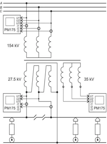
The measurements were made according to ac-cepted program during 24 hours with 1 sec discre-tization. A few power quality analyzers such PM175 are used to record data with time synchro-nization. Simplified scheme of measurements are shown at Fig. 1. The scheme means that devices are connected through current and potential trans-formers at the each level of voltage.
Fig. 1. The scheme of measurements at AC traction substation
Voltage deviations in primary network 154 kV of each traction substation are shown at Fig. 2 dur-ing 24 hours. Voltage level at different substation is various due to power losses in primary network. Besides, the voltage in one phase of 1-st substation is bigger than in other phases.
Voltage regulating devices helps to align volt-ages at other points of coupling either 35 kV or 27.5 kV. Voltage deviations in these networks of one traction substation are shown at Fig. 3. When voltage equalization in 35 kV is needed the com-pensation current may flows throw traction net-work. In this case compensation current causes additional useless power losses.
Fig. 2. Voltage deviations in 154 kV primary networks
Fig. 3. Voltage deviations in 35 kV and 27.5 kV networks
Total harmonic distortion and three-phase unbalance
Voltage total harmonics distortions (THD) for each phase are similar. Voltage THD values ac-cording to standard requirements [4] are below norm only for primary 154 kV networks (Fig. 4). For another traction and regional networks voltage THD values are above norm value.
According to standard [4] the norm of voltage THD values for 110 – 330 kV networks are below 2%. As for 35 kV and 27.5 kV networks the norm values are below 4%.
The norm of voltage unbalance is 2% and it doesn’t depend on the voltage range.
The voltage unbalance series are shown at Fig. 5. As can be seen the voltage unbalance in 154 kV networks are below voltage unbalance in 35 kV networks. Besides the voltage unbalance in 154 kV network is below 2% that complies with the requirements of standard. The voltage unbal-ance in 35 kV network is higher than 2% and its maximum reached within 4.7% value.
Fig. 5. Voltage unbalance in 35 kV and 154 kV networks
Traditionally the voltage unbalance caused by unbalancing currents in a three-phase system. The primary currents at one substation are shown at Fig. 6 as fields of points. Each point is defining the end of primary current vector at complex plot.
Fig. 6. Currents in 154 kV primary network at complex plot
It can be seen from Fig. 6 that currents in sec-ond phase (B) are lower than in other phase. In this case phase A and C are working. The phase B is the least loaded. Besides the phase A has the lowest power factor because the angle of load in this phase is the higher than in other phases.
Detail waveform researching
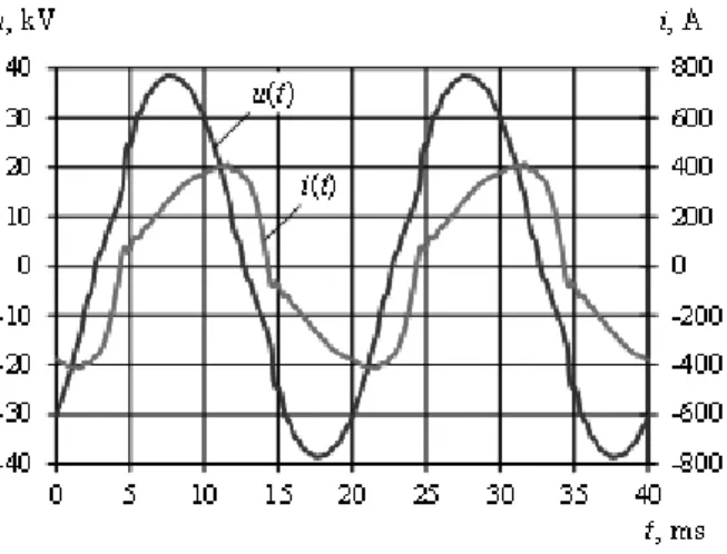
The voltage and current waveforms are very different from the sine (Fig. 7). Besides the current waveform are lags from the voltage waveform due to inductive component in traction load.
Before Fourier analysis check the discreteness of spectrum is needed. This check may be per-formed by comparing RMS values that defined by various methods.
Fig. 7. Voltage and current waveforms in traction network
The RMS values may be evaluated by integra-tion of waveform and discrete Fourier transform methods. So the conditions that used to check spectrum discreteness may be written as follows
2
2 ( )
1 0
1 ( )
T N
k
k u t dt U
T
∫
=∑
=, (1)
2
2 ( )
1 0
1 ( )
T N
k
k i t dt I T
∫
=∑
=, (2) where ( )u t , ( )i t – instantaneous voltage and
cur-rent; U( )k , I( )k – voltage and current RMS
har-monic value; T – fundamental harmonic period, 0.02
As can be seen from table 1 the conditions (1)-(2) are satisfied with 0.001% error. This means that we can consider that voltage and current spec-trums consist from discrete harmonics with quencies that multiples of the fundamental fre-quency.
Table 1 Voltage and current RMS comparing
Definition method Magnitude integration
of waveform discrete Fourier transform
Error, %
U, V 27 317.687 27 317.767 < 0.001
I, A 297.848 297.851 0.001 The relative spectrums of voltage and current at AC traction substation consist of odd harmonics (Fig. 8). The fundamental harmonics are shown not in scale. When spectrums of voltage and currents will be compared it can be seen that in current spectrum with frequency increasing the harmonics values are decreasing. But in voltage spectrum some harmonics are gained and some are weak-ened.
Fig. 8. Voltage and current relative spectrums
For example, in current spectrum the harmonic with a frequency of 150 Hz has a maximum. But in voltage spectrum the harmonic with maximum value has a frequency of 250 Hz. This indicates for non-linear resistance characteristics of traction network as a function of frequency.
Findings
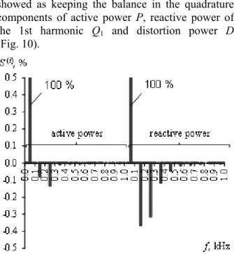
Using these spectra, we can calculate the com-ponents of the balance of the total power in an AC circuit. Notable is the fact that the flows of active and reactive power of the higher harmonics are directed opposite power of the fundamental har-monic (Fig. 9).
This suggests that the AC electric rolling stock is a load at the fundamental frequency and a noise generator on the higher harmonics.
In percentage terms power flows on higher har-monics are less than 1 % and create more disturb-ing impact on related communication devices, automation and remote control than the effect of the losses increasing.
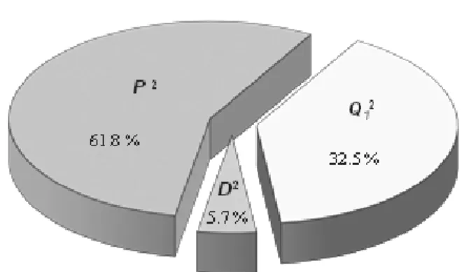
The results of power components evaluation showed as keeping the balance in the quadrature components of active power P, reactive power of the 1st harmonic Q1 and distortion power D (Fig. 10).
Fig. 10. Power balance in the quadrature components The obtained result shows that the total power consists of 61.8% of the active power, 32.5% of the reactive power of the 1st harmonic and 5.7% of the distortion power in the quadrature compo-nents.
Originality and Practical value
The voltage and current spectrums at AC trac-tion substatrac-tion may be considered as spectrums that consist from discrete harmonics with frequen-cies that multiples of the fundamental frequency.
The AC electric rolling stock is a noise genera-tor on the higher harmonics because the flows of active and reactive power of the higher harmonics are directed opposite power of the fundamental harmonic.
Analysis of the quadrature components sug-gests that traditional approaches to reactive power compensation at the fundamental frequency will be sufficiently effective. But the influence of the dis-tortion power on reducing energy losses must be also researched. Besides reactive power compensa-tion should be considered with the issue of reduc-ing the basic power quality indices to standardized values.
Conclusions
1. The most significant power quality indices at AC traction substation are voltage deviation, volt-age unbalance and harmonic distortion.
2. Voltages at the connection points of traction substations to supply lines are complex stationary random process that determines the voltage mode of the external power supply system of each trac-tion substatrac-tion.
3. Voltage waveform distortions according to standard requirements are below norm only for primary networks. On the other connection the
dis-turbances are outside the allowable range. The situation is similar for the voltage unbalance.
4. The flows of active and reactive power of the higher harmonics at AC traction substation are di-rected opposite power of the fundamental har-monic. The power flows on higher harmonics cre-ate the disturbing impact on relcre-ated devices.
5. The total power at AC traction substation consists of 61.8% of the active power, 32.5% of the reactive power of the 1st harmonic and 5.7% of the distortion power in the quadrature compo-nents.
LIST OF REFERENCE LINKS
1. Бадер, М. П. Электромагнитнаясовместимость
/ М. П. Бадер. – М. : УМК МПС РФ, 2002. –
638 с.
2. Босий, Д. О. Оптимізаціякеруваннярегульова
-ною компенсацією реактивної потужності на
тягових підстанціях змінного струму /
Д. О. Босий // Інформ.-керуючі системи на
залізн. трансп. – 2010. – № 1. – С. 24−32.
3. Босий, Д. О. Математичне моделюванняелек
-тротягового навантаження в задачах вивчення
електромагнітних процесів для систем елек
-тропостачання електричного транспорту
змінногоструму / Д. О. Босий, В. Г. Сиченко //
Техн. електродинаміка, тематичний вип. –
2009. – Ч. 3. −С. 86–89.
4. ГОСТ 13109–97. Электрическая энергия. Тре
-бования к качеству электрической энергии в
электрических сетях общего назначения. –
Введ. 1999.01.01. – К. : ГосстандартУкраины, 1999. – 35 с.
5. Контроль потребления электроэнергии с уче
-томеекачества / О. Г. Гриб, В. И. Васильчен
-ко, Г. А. Сендерович и др. ; под ред.
О. Г. Гриба. – Х. : ХНУРЭ, 2010. – 444 с.
6. Кузнецов, В. Г. Электромагнитная совмести
-мость. Несимметрияинесинусоидальность на
-пряжения / В. Г. Кузнецов, Э. Г. Куренный,
А. П. Лютый. – Донецк : Донбасс, 2005. –
249 с.
7. Марквардт, К. Г. Энергоснабжениеэлектрифи
-цированныхжелезныхдорог / К. Г. Марквардт.
– М. : Транспорт, 1982. – 528 c.
8. Полях, О. М. Застосування матриць та графів
до розрахунку систем електропостачання /
О. М. Полях // Вісник Дніпропетр. нац. ун-ту
залізн. трансп. ім. акад. В. Лазаряна. – Д., 2012.
– Вип. 42. – С. 133–137.
9. Сиченко, В. Г. Аналіз режимів напруги на
приєднаннях тягових підстанцій змінного
Дніпропетр. нац. ун-тузалізн. трансп. ім. акад.
В. Лазаряна. – Д., 2009. – Вип. 29. – С. 82–87.
10. Электромагнитная совместимость потребите
-лей / И. В. Жежеленко, А. К. Шидловский,
Г. Г. Пивняк и др. – М. : Машиностроение,
2012. – 351 с.
11. A Comparative Study of Signal Processing and Pat-tern Recognition Approach for Power Quality Dis-turbance Classification / B. K. Panigrahi, S. K. Sinha, A. Mohapatra et al. // IETE Journal of Research. – 2011. – № 57. – P. 5–11.
12. Arrillaga, J. Power System Harmonics / J. Arrillaga, N. R Watson. – New York : John Wiley & Sons, 2004. – 399 p.
13. Bollen, M. H. J. Signal Processing of Power Qual-ity Disturbances / M. H. J. Bollen, I. Y. H. Gu. – Piscataway : NJ, IEEE Press, 2006. – 861 p. 14. Impedances of contact lines and propagation of
current harmonics / A. Zynovchenko, Xie Jian, J. Steffen, K. Franz // Elekrtische Bahnen. – 2006. – №. 5. – P. 12–17.
15. Sutherland, P. E. System impacts evaluation of a single-phase traction load on a 115 kV transmis-sion system / P. E. Sutherland, M. Waclawiak, M. F. McGranaghan // IEEE Transactions on power delivery. – 2006. – Vol. 21, № 2. – P. 837–843.
Д
.
О
.
БОСИЙ
1*1*Каф. «Електропостачаннязалізниць», Дніпропетровськийнаціональнийуніверситетзалізничноготранспортуімені
академікаВ. Лазаряна, вул. Лазаряна, 2, 49010, Дніпропетровськ, Україна, тел. +38 (050) 698 23 95, ел. пошта [email protected]
КОМПЛЕКСНА
ОЦІНКА
ПОКАЗНИКІВ
ЯКОСТІ
ЕЛЕКТРОЕНЕРГІЇ
НА
ТЯГОВИХ
ПІДСТАНЦІЯХ
ЗМІННОГО
СТРУМУ
Мета. Натяговихпідстанціяхзмінногострумузастосовуютьсятриобмотковітрансформатори. Такасхе
-ма живлення призводить до значних спотворень показників якості електроенергії в кожного споживача,
якийживитьсявідтяговоїпідстанції. Найбільшважливимипоказникамиякостідлятяговихпідстанційзмін
-ногострумуєвідхилення, несиметріятагармонійніспотворення напруги. Метоюцієїроботиєкомплексна
оцінкапоказниківякостіелектроенергіїдвохтяговихпідстанцій, якіпаралельнопрацюютьнаоднуміжпід
-станційну зону. Методика. Вимірювання показників якості виконані відповідно до програми протягом
24 годинздискретизацієювчасі 1 с. Застосованодекількааналізаторівпотужності PM175 ізсинхронізацією
вчасі. Вимірювальніприладипідключалисьчерезвідповіднітрансформаторинапругиіструмунакожному
рівні напруги. Результати. Рівень напруги на різних підстанціях відрізняється через втрати потужності
впервинніймережі. Крімтого, напругаводнійфазімережібільша, ніжуіншихфазах. Гармонійніспотво
-реннянапругиможутьбутименшінорми, встановленоїстандартом, лишедляпервинноїмережі 154 кВ. Для
інших – тяговоїта районноїмереж – вониперевищуютьвстановленінорми. Несиметрія напругивмережі
154 кВнижча, ніжурайонніймережі 35 кВ. Крімтого, рівеньнесиметріївпервинніймережівідповідаєви
-могамстандарту. Утойжечасможнавважати, щоспектринапругиіструму містятьдискретні гармонійні
складові, частоти яких кратні основній частоті мережі. Наукова новизна. Напруги в точках приєднання
тяговихпідстанцій до живильноїмережі являють собоюскладнийстаціонарний випадковий процес, який
визначає режим напруги системи зовнішнього електропостачання кожної тягової підстанції. Потоки
активноїтареактивноїпотужностейнавищихгармонікахспрямованіпротилежнопотокампотужностейна
основній гармоніці. Потоки потужностей на вищих гармоніках створюють перешкоджаючий вплив на
суміжні пристрої. Повна потужність тяговоїпідстанції змінногоструму складаєтьсяна 61,8 % зактивної,
32,5 % з реактивної 1-їгармоніки і 5,7 % потужностіспотворення уквадратурних складових. Практична
значимість. Аналізквадратурнихскладовихвказуєнате, щозастосуваннятрадиційноїкомпенсаціїреакти
-вної потужності на основній частоті буде достатньо ефективним. Проте необхідно враховувати вплив
потужності спотворень на зниження втрат електроенергії. Крім того, компенсацію реактивної потужності
необхіднозастосовуватиякспосібзниженняосновнихпоказниківякостіелектроенергіїдонормованихзна
-чень.
Ключовіслова:якістьелектроенергії; зміннийструм; трифазнасистема; тяговапідстанція; вимірювання;
Д
.
А
.
БОСЫЙ
1*1*Каф. «Электроснабжениежелезныхдорог», Днепропетровскийнациональныйуниверситетжелезнодорожного
транспортаимениакадемикаВ. Лазаряна, ул. Лазаряна, 2, 49010, Днепропетровск, Украина, тел. +38 (050) 698 23 95,
эл. почта [email protected]
КОМПЛЕКСНАЯ
ОЦЕНКА
ПОКАЗАТЕЛЕЙ
КАЧЕСТВА
ЭЛЕКТРОЭНЕРГИИ
НА
ТЯГОВЫХ
ПОДСТАНЦИЯХ
ПЕРЕМЕННОГО
ТОКА
Цель. Натяговыхподстанцияхпеременноготокаприменяютсятрехобмоточныетрансформаторы. Такая
схемапитания приводит к значительным искажениямпоказателей качества электроэнергии укаждого по
-требителя, который питаетсяот тяговойподстанции. Длятяговыхподстанций переменноготока наиболее
важнымипоказателямикачестваэлектроэнергииявляютсяотклонения, несимметрияигармоническиеиска
-жениянапряжения. Цельданнойработысостоит вкомплекснойоценкепоказателей качестваэлектроэнер
-гии для двух тяговых подстанций, которые параллельно работают на одну межподстанционную зону.
Методика. Измеренияпоказателейкачествавыполненывсоответствииспрограммойнапротяжении 24 часов
сдискретизацией во времени 1 с. Применено несколько анализаторов мощности PM175 с синхронизацией
времени. Измерительныеприборыподключалисьчерезсоответствующиетрансформаторынапряженияитока
на каждомуровненапряжения. Результаты. Уровень напряжениянаразных подстанцияхотличается ввиду
потерьмощности в первичной сети. Крометого, напряжение водной фазе больше, чем востальных фазах.
Гармоническиеискажения могутбытьниже нормы, установленной стандартом, только для первичной сети
154 кВ. Длядругих – тяговойирайоннойсетей – гармоническиеискаженияпревышаютустановленныенормы.
Несимметриянапряженийвсети 154 кВниже, чемврайоннойсети 35 кВ. Крометого, уровеньнесимметрии
впервичнойсетисоответствуеттребованиямстандарта. Втожевремяможносчитать, чтоспектрынапряже
-нияи тока содержат дискретныегармонические составляющие, частотыкоторых кратны основной частоте
сети. Научнаяновизна. Напряженияв точкахприсоединения тяговыхподстанцийк питающейсетипред
-ставляютсобойсложныйстационарныйслучайныйпроцесс, которыйопределяетрежимнапряжениясисте
-мывнешнегоэлектроснабжениякаждойтяговойподстанции. Потокиактивнойиреактивноймощностейна
высших гармониках направлены противоположно потокам мощностей на основной гармонике. Потоки
мощностейнавысшихгармоникахсоздают мешающеевлияниенасмежныеустройства. Полнаямощность
тяговойподстанциипеременноготокасостоитна 61,8 % изактивной, 32,5 % изреактивной 1-йгармоники
и 5,7 % мощности искажений в квадратурных составляющих. Практическая значимость. Анализ
квадратурных составляющих указывает на то, что применение традиционной компенсации реактивной
мощности на основной частоте будет достаточно эффективным. Но также необходимо учесть влияние
мощности искажений на общее снижение потерь электроэнергии. Кроме того, компенсацию реактивной
мощностинеобходимо применятькак способсниженияосновных показателейкачества электроэнергиидо
нормируемыхзначений.
Ключевые слова: качество электроэнергии; переменный ток; трехфазная система; тяговая подстанция;
измерения; гармоника; искажения; несимметрия; потокимощностей
REFERENCES
1. Bader M.P. Elektromagnitnaya sovmestimost [Electromagnetic compatibility]. Moscow, UMK MPS RF Publ., 2002. 638 p.
2. Bosiy D.O. Optymizatsiia keruvannia rehulovanoiu kompensatsiieiu reaktyvnoi potuzhnosti na tiahovykh pid-stantsiiakh zminnoho strumu[Optimizing the controlled compensation of reactive power at the AC traction substations]. Informatsiino-keruiuchi systemy na zaliznychnomu transporti– Information and control systems on railway transport, 2010, no. 1, pp. 24-32.
4. GOST 13109-97. Elektricheskaya energiya. Trebovaniya k kachestvu elektricheskoy energii v setyakh obshschego naznacheniya [Electrical energy. Power quality requirements for electrical energy in electric util-ity networks]. Kiev, Gosstandart Ukrainy Publ., 1999. 35 p.
5. Grib O.G., Vasilchenko V.I., Gromadskiy Yu.S., Dovgalyuk O.N., Manov I.A., Rozhkov P.P., Sapryka V.A., Senderovich G.A., Shcherbakova P.G. Kontrol potrebleniya elektroenergii s uchetom yeye kachestva [Electric energy consumption control taking into account its quality]. Kharkov, KhNURE Publ., 2010. 444 p.
6. Kuznetsov V.G., Kurennyy E.G., Lyutyy A.P. Elektromagnitnaya sovmestimost. Nesimmetriya i nesinusoidal-nost napryazheniya [Electromagnetic compatibility. Voltage unbalance and harmonic distortion]. Donetsk, Donbass Publ., 2005. 249 p.
7. Markvardt K.G. Energosnabzheniye elektrifitsirovannykh zheleznykh dorog [Power supply of electric rail-ways]. Moscow, Transport Publ., 1982. 528 p.
8. Poliakh O.M. Zastosuvannia matryts ta hrafiv do rozrakhunku system elektropostachannia[Using the matrices and graphs for power systems evaluating]. Visnyk Dnipropetrovskoho natsionalnoho universytetu zaliznychnoho transportu imeni akademika V. Lazariana [Bulletin of Dnipropetrovsk National University named after Academician V. Lazaryan], 2012, issue 42, pp. 133-137.
9. Sychenko V.H., Bosyi D.O. Analiz rezhymiv napruhy na pryiednanniakh tiahovykh pidstantsii zminnoho strumu [The mode of voltage analysis at AC traction substations]. Visnyk Dnipropetrovskoho natsionalnoho universytetu zaliznychnoho transportu imeni akademika V. Lazariana [Bulletin of Dnipropetrovsk National University named after Academician V. Lazaryan], 2009, issue 29, pp. 82-87.
10. Zhezhelenko I.V., Shidlovskiy A.K., Pivnyak G.G., Sayenko Yu. L., Noyberger N.A. Elektromagnitnaya sovmestimost potrebiteley [Electromagnetic compatibility of power consumers]. Moscow, Mashinostroyeniye Publ., 2012. 351 p.
11. Panigrahi B.K., Sinha S.K., Mohapatra A., Dash P., Mallick M.K. A Comparative Study of Signal Processing and Pattern Recognition Approach for Power Quality Disturbance Classification. IETE Journal of Research, 2011, no. 57, pp. 5-11.
12. Arrillaga J., Watson N.R. Power System Harmonics. New York, John Wiley & Sons Publ., 2004, 399 p. 13. Bollen M.H.J., Gu I.Y.H. Signal Processing of Power Quality Disturbances. Piscataway, NJ, IEEE Press Publ.,
2006. 861 p.
14. Zynovchenko Andriy, Xie Jian, Jank Steffen, Klier Franz. Impedances of contact lines and propagation of cur-rent harmonics. Elekrtische Bahnen, 2006, no. 5, pp. 12-17.
15. Sutherland P.E., Waclawiak M., McGranaghan M.F. System impacts evaluation of a single-phase traction load on a 115 kV transmission system. IEEE Transactions on power delivery, 2006, vol. 21, no. 2, pp. 837-843.
D. Sc. (Phys.&Math), Prof. V. I. Gavrilyuk (Ukraine); D. Sc. (Tech.), Prof. S. P. Denisyuk (Ukraine) recommended this article to be published.