Hoarcă Ioan Cristian
1)2)1) National Research and Development Institute for Cryogenics and Isotopic Technologies ICIT
Rm. Valcea, Romania
2) University Politehnica of Bucharest, 313 Splaiul Independentei, 060042, Bucharest, Romania
Marian Raducu
3)3) University of Pitesti, 1 Targu din Vale, Arges, 110040, Pitesti, Romania
Abstract –In this paper the study about micro-inverter is proposed, based on the three Maximum Power Point Tracking (MPPT) technique for photovoltaic (PV) system: Perturb and Observe algorithm (P&O),
advanced Extremum Seeking (aES), modified
Extremum Seeking (mES) controls. The study is made with the dynamic standard test EN 50530 which uses various test sequences. The simulation results allow the comparison of MPPT efficiency for the three algorithms that have been tested. The dynamic performance is tested for three levels of frequency: low, medium and high frequency. MPP efficiency at low frequency is 97%, for advanced Extremum Seeking Control (aESC). MPP efficiency descends to 96% for modified Extremum Seeking Control (mESC) and 94% for P&O algorithm.
Keywords-component: Micro-inverter; MPPT controllers; Extremum seeking control (ESC); Perturb and Observe algorithm (P&O);
I. INTRODUCTION
The photovoltaic panels can be arranged in various configurations to directly determine the structure and the topology of the electronic device which may be a DC-DC converter or DC-AC when the plant is connected to the grid.
The photovoltaic panels can be arranged in various configurations to directly determine the structure, the costs, the operation and the efficiency of the entire PV system. Below the most commonly used PV configurations are shown. [1,2].
1.1. Centralized configuration or with central inverter. It is mainly used in photovoltaic installations with a nominal power (P>10kW), the modules are grouped into short or long strings which are connected to a central inverter. Each string has one blocking diode whose purpose is to prevent the reverse flow from the network ( see Figure 1).
1.2. String configuration. String configuration or with string inverters, in which each string is connected to a DC-AC inverter, each string has implemented its own MPPT.(see Figure 1).
1.3. Multistring configuration combines the advantages of the centralized configuration with the advantages of the string configuration. Each string is provided with a DC-DC converter. Each string has implemented its own MPPT using a common DC-AC converter (see Figure 1).
1.4. AC modular configuration. In this configuration, the PV module and the inverter are integrated in a single device, to form a unit equipped with a MPPT algorithm [2]. There are known as: micro-inverters, integrated modules (MIC) or AC modules ( see Figure 1).
This paper is organized as follows. The second section presents the PV panel model used in simulation. The third section deals with the dynamic standard test EN 50530. The MPPT based on aESC, mESC and P&O algorithm are shown in Section 4. Section 5 deals with the micro-inverter structure and the simulation diagram for the tested algorithms. The results for the MPP efficiency at low, medium, high frequency, noisy PV and for a sunny/cloudy day are discussed in Section 6. The last section concludes the paper.
II. PVPANELMODEL
The electric power of the photovoltaic cells is small, they are associated in series (36 or 72 cells connected in series), thus obtaining a PV module. The modelling of the PV panels can be made using the simple diode model or the double diode model [1,3]. The PV module has the following parameters: the short-circuit current ( =7.8A), the open-circuit voltage ( =21V), the current at MPP ( =6.72A), the voltage at MPP =12.7V), measured under standard test conditions: irradiation intensity =1000 ), mass index of the air (AM=1.5),
and temperature [4,5].
The I-U characteristic for the PV panel is given by the equation:
(1)
where and represents the voltage and output current of the PV module, is the series resistance
of the PV module, ( the
irradiation to short-circuit current gain, G the level of instantaneous irradiation, is the reverse saturation current, represents the diode ideality factor, is the thermal voltage, -Boltzmann’s constant, -electron charge, -reference temperature,
III. PVPATTERNS
The dynamic standard test EN 50530 (RO 50530), defines a test procedure to measure the MPPT efficiency of the grid-connected PV systems, with a PV simulator which simulates the output characteristics of a PV source. Although this test is designed for inverters it can be used in DC-DC converters to evaluate the performance of the MPPT algorithm.
The dynamic MPPT efficiency test under rapid changes of weather conditions is characterized by the combination of various ramp profiles over a certain time interval. The full profile consists of an insolation ramp with different slopes and levels of sun exposure:
low and medium insolation ( ,
medium and high ( , and very
low insolation ( [8]. For testing the dynamic efficiency of the MPPT different frequencies will be used: low frequency, medium frequency, high frequency. Figs. 2 and 3 show the test sequences for low-medium (100–500 ) and medium–high (300–1000 ). Each test sequence consists of n consecutive ramps (up and down). For the transition from low to high, the insolation is kept constant for a certain period of time, referred to as the dwell time. A settling time is used, which allows the MPPT method to stabilize before each test sequence. For the analysis of the MPPT efficiencies, only the evaluation time periods are taken into account, the initial settling time is not taken into account. Fig. 4 shows a test sequence at very low irradiance. This is used to assess the MPPT performance of the grid connected PV system, start-up and shut down moments.
The dynamic efficiency of the MPPT ( ) is calculated with the following equation:
=
(2)
where and represent the instantaneous voltage and current at the output of the PV array simulator. The represents the available maximum power of the PV simulator with respect to the instantaneous . represents the time duration of the whole sequence [9].
IV. MPPTCONTROLLERS
The efficiency of a photovoltaic system is mainly influenced by three factors: the PV cell efficiency, the efficiency of the DC-DC converter or of the DC-AC converter and the efficiency of the MPPT algorithm [9]. Figure 5 shows a block diagram of a MPPT system for a photovoltaic plant equipped with DC-DC convertor [1].
The MPPT techniques are classified mainly into three groups [10]:
a) Indirect techniques (off-line) that use the technical data of the PV panels to estimate the MPP.
a) Direct techniques (on-line) that use the measured parameters (U, I) in real time: the Incremental conductance algorithm (IC) or the Perturb and Observe algorithm (P&O).
b) Other methods which include a combination of these two methods or numerical calculation: the artificial neural networks method, the fuzzy logic controller-based method and the evolutionary algorithms [4].
. Figure 1 .PV system configurations central inverter, string, multistring, with AC modules.
Figure 2. Ramptest sequence, low–medium insolation (adapted from [9]).
. Figure 3 . Ramp test sequence, medium–high insolation (adapted from [9]).
Figure 4 . Start-up and shut down test, (adapted from [9]).
There are advanced techniques to find MPP as Extremum Seeking Control (ESC). The ES control is a real-time optimization method, used to increase the search speed and the tracking accuracy of the MPP at PV panels in different operating conditions [11]. The ES control techniques are classified into three groups: the classical ES control is based on the scalar scheme, but without the use of the high-pass (HPF) and low-pass filters (LPF) (see Figure 6), a modified ES (mES) and advanced control scheme (aES) [12,13].
4.1. MPPT based on mESC
Use a band-pass filter (BPF=HPF+LPF) instead of a series connection of HPF and LPF used in the classical ES control scheme (see Figure 7) [13,14].
In mESC simulation the following parameters are used: the cut-off frequency of the LPF2 (bl2=5.5fd=550Hz), the cut-off frequency of the LPF1 (bl1=1.9fd=190Hz), the cut-off frequency of the BPF (bh=0.1fd=10 Hz), the dither frequency fd=1/ =100Hz, Iref(0)=0.1A, the loop gain (ysd=4fd=400 Hz), the sine amplitude (k2=0.1),
4.2. MPPT based on aESC
When compared to the mES scheme the aES control scheme shows the following: the amplification amplitude of the sinusoidal signal with the magnitude H1 of the PV power, which is variable in time (see Figure 8). For mESC and classical ES control a compromise is performed between the performance indicators, because the dither amplitude controls the search speed and the tracking accuracy [11,15].
The parameters used in the aESC simulation: the cut-off frequency of the LPF2 (bl2=5.5fd=550Hz), the cut-off frequency of the LPF1 (bl1=1.9fd=190Hz), the loop gain (ysd=4fd=400 Hz). For the MPPT search , aESC uses a higher dither
amplitude to quickly search the MPP (k2=3), the cut-off frequency of the BPF (bh=0.1fd=10 Hz). The common parameters for all three algorithms are: dither frequency fd=1/ =100Hz, Iref(0)=0.1A.
4.3. MPPT based on P&O algorithm
P&O algorithm is one of the most used MPPT algorithms. The logical scheme for the Perturb and Observe algorithm is shown in Figure 9. The maximum power point is calculated by successive attempts: the voltage across the PV generator is amended and then the output power is compared with the previous power [16]. The process continues until:
0
dP dV
Perturb and Observe algorithm is a direct technique that uses the measured parameters (U, I) of the PV panel to estimate the MPP [17]. The problem of the maximum power point lies in the automatic determination of the output voltage or the output current so that the extracted power and the supplied power to the consumer are maximized [18].
V. MICROINVERTERSTRUCTURE
DC-AC converters are power circuits that convert DC power into AC, and they are commonly called inverters. Low power inverters used in photovoltaic installations have the power range between 100-250W having a conversion of 90% [19]. They are known under the name of micro-inverters (MI) or AC modules. Each PV panel is provided with its own inverter and MPPT algorithm. Technically, a MI contains of the following components, as shown in Figure 10:
- DC-DC converter;
Figure 6. Classical ES control scheme (adapted from [14]).
- Inverter
- Control circuitry
Figure 10 presents the diagram of the micro-inverter based on a double conversion. The energy generated from the PV panels at low voltage (24–37.6 V) is processed by a DC/DC push–pull converter which supplies a 400 V DC voltage to the power inverter. In MI modeling, DC-AC inverter is considered as a load for the DC-DC converter, although the load is connected to the AC side of the micro-inverter. This modeling is quite reasonable [20,21].
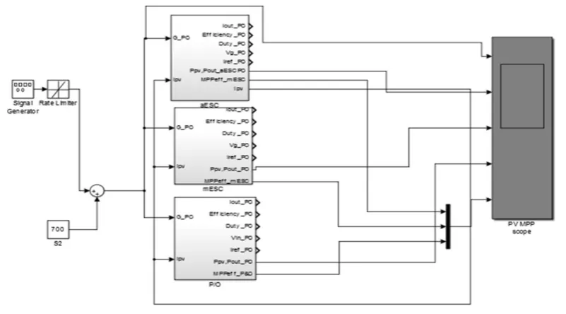
This article is focused on the DC-DC converter. PV panel providing a 50 V output on the DC bus. No results will be presented for DC-AC converter. The performance of the three algorithms (mESC, aESC and P&O) for low, medium, high frequency, noisy PV and for a sunny/cloudy day are tested (Figure 11).
VI. RESULTSFORTRACKINGEFFICIENCY
The results for tracking efficiency at low, medium, high frequency, noisy PV and for a sunny/cloudy day are presented in the following diagrams. The behaviour of the three test algorithms: aESC, mESC, Perturb and Observe algorithm (P&O), functioning under dynamic conditions results from these diagrams.
6.1. PV patterns of low frequency
For the simulation where a low frequency (f=0.0628Hz, T=15s) and a rate limiter (100,-100)
where used the following can be noted:
- aESC and mESC presents oscillations in tracking the MPP, at the beginning of the testing
process ( ), higher for mESC
algorithm.
- Perturb and Observe algorithm rapidly loses tracking control of the MPP to sudden changes of irradiance. The MPP efficiency for the three algorithms is maximum for the aESC algorithm, followed by mESC and P&O (see Figure 12). Table 1 shows the values for the MPP efficiency for a low frequency.
6.2. PV patterns of medium frequency
For the simulation of the micro-inverter at f=0.628Hz, T=1.5s, with a rate limiter (5000; -5000) the results are:
- aESC has high ripple compared to mESC.
- mESC algorithm shows large oscillations to the rapid decrease of irradiance.
- P&O algorithm loses tracking control of the MPP during rapid decrease of irradiance.
In terms of efficiency: aESC has increased efficiency compared to mESC and P&O (see Figure 13). At the same frequency f=0.628Hz and with a rate limiter (1000, -1000) the ripple in the MPP tracking, for aESC and mESC decreases. P&O has high ripple
Figure 8. Advanced extremum seeking (aES) control scheme (adapted from [4]).
Figure 9. Logical scheme for the agorithm Perturb and Observe.
but it does not lose the tracking of the MPP.
The MPP efficiency for aESC and mESC is almost the same, but for P&O the value fluctuates (see Figure 14). Table 2 and Table 3 show the values for the MPP efficiency in case of a medium frequency.
6.3. PV patterns of high frequency
The simulation of the micro-inverter at f=3.14Hz, T=0.31s, with a rate limiter (10000; -10000) as well as f=6.28Hz, T=0.15s, with a rate limiter (10000; -10000) shows the following (Figure 15, Figure 16):
- aESC has high ripple in MPP tracking, to sudden decrease of irradiance.
- mESC shows smaller ripple, but loses tracking control of the MPP. P&O loses tracking control of the MPP. Table 4 shows the values for the MPP efficiency in case of a high frequency.
6.4. Noisy PV patterns
When testing with noise for f=0.628 Hz, T=15 s, with a rate limiter (1000, -1000), the aESC and the mESC show small ripple in the MPP tracking. The Perturb and Observe algorithm shows high ripple with the loss of the MPP tracking control. The performance is improved once the frequency decreases (f=0.0628) to all three algorithms (see Figure 17, Figure 18). Table 5 and Table 6 show the values for the MPP efficiency in case of noisy PV patterns.
6.5. PV patterns for a sunny/cloudy day
Figure.11 Simulation diagram for the three tested algorithms.
Figure 13.Simulation diagram for f=0.628Hz, T=15s (rate limiter: 5000,-5000)
The simulations at medium frequency (Figure 19) for a sunny day reveal:
- all algorithms have good behavior.
- P&O ripple at low irradiance is increased compared to the ripple of mESC. The aESC ripple at low irradiance is reduced compared to the P&O algorithm.
- MPP efficiency is following: aESC, mESC and P&O. Table 7 shows the values for the MPP
efficiency at a medium frequency for a sunny day.
The simulations at a high frequency (Figure 20) for a sunny day reveal:
- P&O, aESC have increase ripple.
- the ripple for mESC is the lowest compared to the other two algorithms, aESC and P&O.
- in terms of efficiency: mESC is superior to aESC and P&O, also P&O fluctuates according to irradiance. Table 8 shows the values for the MPP efficiency at high frequency for a sunny day.
Figure.12 Simulation diagram for f=0.0628Hz, T=15s Figure 15.Simulation diagram for f=3.14Hz, T=0.31s (rate
limiter: 10000,-10000)
Figure 16.Simulation diagram for f=6.28Hz, T=0.15s (rate limiter: 10000,-10000)
Figure 17.Simulation diagram for f=0.628Hz, T=1.5s (rate limiter: 1000,-1000)
Figure 18.Simulation diagram for f=0.0628Hz, T=15s (rate limiter: 500,-500)
Figure 19.Simulation diagram at medium frequency for asunny day (f=0.628Hz, T=1.5s,rate limiter:
1000,-1000)
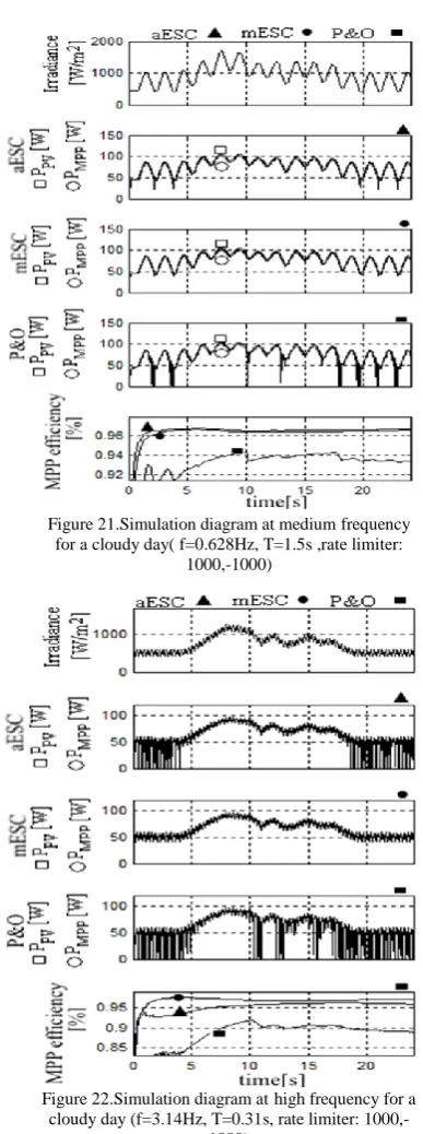
The simulations at a medium frequency (Figure 21) for a cloudy day reveals:
- P&O ripple at low irradiance is increased, P&O algorithm has the disadvantage that it may not track the MPP during rapid changes of weather.
- efficiency is good for aESC and mESC , but for P&O fluctuates according to irradiance. Table 9 shows the values for MPP efficiency at medium frequency for a cloudy day.
The simulations at high frequency (Figure 22) for a cloudy day reveals:
- aESC, P&O has an increase ripple, at low irradiance.
- ripple for mESC is the lowest compared to the other two algorithms aESC and P&O.
the three MPPT algorithms: aESC, mESC and P&O. The dynamic conditions were achieved by using the dynamic standard EN 50530 (RO 50530) which is a new standard for evaluating the dynamic performances of a PV system.
The simulation results show a close dependency between the dynamic performances of the three algorithms (aESC, mESC si P&O) and the parameters used in simulation.
The testing was done at different frequency levels: low, medium and high. For low frequency the aESC and mESC algorithms show oscillations in the MPP tracking, the P&O algorithm loses the tracking control of the MPP to sudden changes of irradiance. The MPP efficiency is 97% for aESC, 96% for mESC and 94% for the P&O algorithm. For a medium frequency the P&O algorithm loses the tracking control of the MPP during a rapid decrease of irradiance. The MPP efficiency has the following values: 96% aESC, 95.5% mESC and 88% for P&O. For a high frequency aESC has a high ripple in the MPP tracking, mESC and P&O lose the tracking control of the MPP. The MPP efficiency is 90% aESC, 85% mESC and 80% for P&O. The MPP efficiency at a high frequency for a sunny day is: 95.5% aESC , 97% mESC and 93% for P&O. The MPP efficiency at a high frequency for a cloudy day is: 96% aESC, 97% mESC and 90% for P&O.
The best results are obtained from the dynamic testing of aESC and mESC algorithms, but when the frequency increases the performances of the mESC algorithm (MPP efficiency), for a sunny/cloudy day outperforms the other algorithms in terms of efficiency.
ACKNOWLEDGMENT
Work under PhD stage, contract number: SD4/27/18.10.2013
LIST OF ABBREVIATIONS
MPPT Maximum power point tracking MPP Maximum power point
P&O Perturb and Observe IC Incremental conductance ESC Extremum seeking control ES Extremum seeking scheme BPF Band pass filter
LPF Low pass filter HPF High pass filter MIC Integrated modules PV Photovoltaic G Irradiation intensity
aES Advanced extremum seeking aESC Advanced extremum seeking control mES Modified extremum seeking mESC Modified extremum seeking control
Figure 21.Simulation diagram at medium frequency for a cloudy day( f=0.628Hz, T=1.5s ,rate limiter:
1000,-1000)
Figure 22.Simulation diagram athigh frequency for a cloudy day (f=3.14Hz, T=0.31s, rate limiter:
Energy Reviews February 2014:30:796–807.
[3] Prabodh Bajpai, Vaishalee Dash. Hybrid renewable energy systems for power generation in stand-alone applications: A review. Renewable and Sustainable Energy Reviews June 2012:16(5):2926–2939.
[4] Cristian Hoarcă, Marian Răducu. Performance comparison of three MPPT algorithms: aESC, mESC and P&O. 2015 7th International Conference on Electronics, Computers and Artificial Intelligence (ECAI) 25-27 June 2015:35-42. [5] Ishaque K, Salam Z, Syafaruddin. A comprehensive
MATLAB Simulink PV system simulator with partial shading capability based on two-diode model. Sol Energy 2011;85:2217-27.
[6] Liu F, Duan S, Liu F, Liu B, Kang Y. A variable step size INC MPPT method for PV systems. IEEE T Ind Electron 2008;55(7):2622-8.
[7] Esram T, Chapman PL. Comparison of photovoltaic array maximum power point tracking techniques. IEEE T Energy Conver 2007;22(2):439-49.
[8] Bründlinger R et al. prEN 50530 – The new European standard for performance characterisation of PV inverters. In: 24th Eur Photovoltaic Solar Energy Conf, 2009.
[9] Kashif Ishaque, Zainal Salam, George Lauss. The performance of perturb and observe and incremental conductance maximum power point tracking method under dynamic weather conditions, Applied Energy 2014:119: 228– 236.
[10] Bhatnagar Pallavee, R. Nema. Maximum power point tracking control techniques state of the art in Photovoltaic application. IEEE Trans. Energy Convers 2013; 23:224-241. [11] N. Bizon. Energy harvesting from the PV Hybrid Power
Source. Energy 2013;52(1):297-307.
[12] Akyuz E, Coskun C, Oktay Z, Dincer I. A novel approach for estimation of photovoltaic energy efficiency. Energy 2012;44(1):1059:66.
[13] N. Bizon. On tracking robustness in adaptive extremum seeking control of the fuel cell power plants. Appl Energy 2010;87(10):3115-30.
[14] Karlis AD, Kottas TL, Boutalis YS. A novel maximum power point tracking method for PV systems using fuzzy cognitive networks (FCN). Electr Pow Syst Res 2007;77(3-4):315-27. [15] N. Bizon. Energy harvesting from the FC stack that operates
using the MPP tracking based on modified extremum seeking control. Appl Energy 2013;104:326-336.
[16] Bhatnagar Pallavee, R. Nema. Maximum power point tracking control techniques state of the art in Photovoltaic application. IEEE Trans. Energy Convers 2013; 23:224-241. [17] Caluianu Ionuţ-Răzvan. Increasing energy productivity of
photovoltaic panels, PhD thesis (Creşterea productivităţii energetice a panourilor fotovoltaice, Teză de doctorat), Bucureşti, 2011.
[18] R. Reinoso Carlos Sanchez, H. Milone Diego, H. Buitrago Roman. Simulation of photovoltaic centrals with dynamic shading. Appl. Energy January 2013;103(2):278-289. [19] Hadeed Ahmed Sher, Khaled E. Addoweesh. Micro-inverters
— Promising solutions in solar photovoltaics. Energy for Sustainable Development December 2012: 16(4):389–400.
TABLES:
TABLE 1. The values for MPP efficiency in case of low frequency.
MPP efficiency aESC mESC P&O
97% 96% 94%
TABLE 2. The values for MPP efficiency in case of medium frequency (rate limiter 5000; -5000).
MPP efficiency aESC mESC P&O 96% 95.5% 88%
TABLE 3. The values for MPP efficiency in case of medium frequency (rate limiter 1000; -1000).
MPP efficiency aESC mESC P&O 96.5% 95.5% 92%
TABLE 4. The values for MPP efficiency in case of high frequency
MPP efficiency aESC mESC P&O
90% 85% 80%
TABLE 5. The values for MPP efficiency in case of noisy PV patterns(f=0.628 Hz).
MPP efficiency aESC mESC P&O
96.5% 95% 88%
TABLE 6. The values for MPP efficiency in case of noisy PV patterns(f=0.0628 Hz).
MPP efficiency aESC mESC P&O
97% 96% 94%
TABLE 7. The values for MPP efficiency at medium frequency for a sunny day.
MPP efficiency aESC mESC P&O 97% 96.5% 94%
TABLE 8. The values for MPP efficiency at high frequency for a sunny day.
MPP efficiency aESC mESC P&O
95.5% 97% 93%
TABLE 9. The values for MPP efficiency at medium frequency for a cloudy day.
MPP efficiency aESC mESC P&O 97% 96.5% 94%
TABLE 10. The values for MPP efficiency at high frequency for a cloudy day.
MPP efficiency aESC mESC P&O
![Figure 4 . Start-up and shut down test, (adapted from [9]).](https://thumb-us.123doks.com/thumbv2/123dok_us/7807586.2085398/2.595.65.251.663.738/figure-start-shut-test-adapted.webp)
![Figure 6. Classical ES control scheme (adapted from [14]).](https://thumb-us.123doks.com/thumbv2/123dok_us/7807586.2085398/3.595.110.528.60.150/figure-classical-es-control-scheme-adapted.webp)
![Figure 8. Advanced extremum seeking (aES) control scheme (adapted from [4]).](https://thumb-us.123doks.com/thumbv2/123dok_us/7807586.2085398/4.595.69.496.70.250/figure-advanced-extremum-seeking-aes-control-scheme-adapted.webp)