53-1003629-01
31 March 2015
FastIron Ethernet Switch
Software Defined
Networking (SDN)
Configuration Guide
© 2015, Brocade Communications Systems, Inc. All Rights Reserved.
ADX, Brocade, Brocade Assurance, the B-wing symbol, DCX, Fabric OS, HyperEdge, ICX, MLX, MyBrocade, OpenScript, The Effortless Network, VCS, VDX, Vplane, and Vyatta are registered trademarks, and Fabric Vision and vADX are trademarks of Brocade
Communications Systems, Inc., in the United States and/or in other countries. Other brands, products, or service names mentioned may be trademarks of others.
Notice: This document is for informational purposes only and does not set forth any warranty, expressed or implied, concerning any equipment, equipment feature, or service offered or to be offered by Brocade. Brocade reserves the right to make changes to this document at any time, without notice, and assumes no responsibility for its use. This informational document describes features that may not be currently available. Contact a Brocade sales office for information on feature and product availability. Export of technical data contained in this document may require an export license from the United States government.
The authors and Brocade Communications Systems, Inc. assume no liability or responsibility to any person or entity with respect to the accuracy of this document or any loss, cost, liability, or damages arising from the information contained herein or the computer programs that accompany it.
The product described by this document may contain open source software covered by the GNU General Public License or other open source license agreements. To find out which open source software is included in Brocade products, view the licensing terms applicable to the open source software, and obtain a copy of the programming source code, please visit http://www.brocade.com/support/oscd.
Contents
Preface...5
Document conventions...5
Text formatting conventions... 5
Command syntax conventions... 5
Notes, cautions, and warnings... 6
Brocade resources... 7
Contacting Brocade Technical Support...7
Document feedback... 8
About This Document... 9
Supported hardware...9
What’s new in this document ... 9
How command information is presented in this guide...10
OpenFlow... 11
Overview of OpenFlow...11
Flow table entries... 13
OpenFlow actions ... 14
OpenFlow Controller... 15
Considerations and limitations for configuring OpenFlow... 15
OpenFlow hybrid switch mode and OpenFlow hybrid port mode ...16
Hybrid switch mode...16
Hybrid port mode...16
Configuring OpenFlow... 19
Enabling OpenFlow on devices...19
Connecting to an OpenFlow controller...21
Setting up SSL encryption for controller connections... 21
Configuring multiple controller connections... 22
Configuring the system parameters for OpenFlow...22
Configuring the default action... 23
Displaying the OpenFlow status on the device... 23
Displaying the OpenFlow status...24
Displaying the configured connections to controllers... 24
Displaying the data path ID of the device...25
Displaying the OpenFlow flows... 25
Purge-time for OpenFlow... 26
Administrating OpenFlow... 27
Clearing the OpenFlow statistics...27
Deleting the OpenFlow flows... 27
Show tech... 27
OpenFlow configuration considerations... 28
Behavior of ports and devices...28
Removing an OpenFlow configuration from a device... 29
OpenFlow 1.3... 31
OpenFlow instructions...36
OpenFlow actions... 39
Scaling considerations... 40
Multiple controller connections...41
Asynchronous configuration...41
Supported OpenFlow messages...42
Output port Normal action...43
Group table... 44
Scaling group numbers... 45
Considerations and limitations for group tables... 45
Group events...46
Enqueue...47
Configuring OpenFlow Enqueue...47
Limitations...48
Metering... 48
Meter statistics... 50
Limitations...50
Preface
● Document conventions...5
● Brocade resources... 7
● Contacting Brocade Technical Support...7
● Document feedback... 8
Document conventions
The document conventions describe text formatting conventions, command syntax conventions, and important notice formats used in Brocade technical documentation.
Text formatting conventions
Text formatting conventions such as boldface, italic, or Courier font may be used in the flow of the text to highlight specific words or phrases.
Format Description
bold text Identifies command names
Identifies keywords and operands
Identifies the names of user-manipulated GUI elements Identifies text to enter at the GUI
italic text Identifies emphasis
Identifies variables and modifiers Identifies paths and Internet addresses Identifies document titles
Courier font Identifies CLI output
Identifies command syntax examples
Command syntax conventions
Bold and italic text identify command syntax components. Delimiters and operators define groupings of parameters and their logical relationships.
Convention Description
bold text Identifies command names, keywords, and command options.
Convention Description
value In Fibre Channel products, a fixed value provided as input to a command option is printed in plain text, for example, --show WWN.
[ ] Syntax components displayed within square brackets are optional. Default responses to system prompts are enclosed in square brackets. { x | y | z } A choice of required parameters is enclosed in curly brackets separated by
vertical bars. You must select one of the options.
In Fibre Channel products, square brackets may be used instead for this purpose.
x | y A vertical bar separates mutually exclusive elements.
< > Nonprinting characters, for example, passwords, are enclosed in angle brackets.
... Repeat the previous element, for example, member[member...].
\ Indicates a “soft” line break in command examples. If a backslash separates two lines of a command input, enter the entire command at the prompt without the backslash.
Notes, cautions, and warnings
Notes, cautions, and warning statements may be used in this document. They are listed in the order of increasing severity of potential hazards.
NOTE
A Note provides a tip, guidance, or advice, emphasizes important information, or provides a reference to related information.
ATTENTION
An Attention statement indicates a stronger note, for example, to alert you when traffic might be interrupted or the device might reboot.
CAUTION
A Caution statement alerts you to situations that can be potentially hazardous to you or cause damage to hardware, firmware, software, or data.
DANGER
A Danger statement indicates conditions or situations that can be potentially lethal or extremely hazardous to you. Safety labels are also attached directly to products to warn of these conditions or situations.
Brocade resources
Visit the Brocade website to locate related documentation for your product and additional Brocade resources.
You can download additional publications supporting your product at www.brocade.com. Select the Brocade Products tab to locate your product, then click the Brocade product name or image to open the individual product page. The user manuals are available in the resources module at the bottom of the page under the Documentation category.
To get up-to-the-minute information on Brocade products and resources, go to MyBrocade. You can register at no cost to obtain a user ID and password.
Release notes are available on MyBrocade under Product Downloads.
White papers, online demonstrations, and data sheets are available through the Brocade website.
Contacting Brocade Technical Support
As a Brocade customer, you can contact Brocade Technical Support 24x7 online, by telephone, or by e-mail. Brocade OEM customers contact their OEM/Solutions provider.
Brocade customers
For product support information and the latest information on contacting the Technical Assistance Center, go to http://www.brocade.com/services-support/index.html.
If you have purchased Brocade product support directly from Brocade, use one of the following methods to contact the Brocade Technical Assistance Center 24x7.
Online Telephone E-mail
Preferred method of contact for non-urgent issues:
• My Cases through MyBrocade • Software downloads and licensing
tools
• Knowledge Base
Required for Sev 1-Critical and Sev 2-High issues:
• Continental US: 1-800-752-8061 • Europe, Middle East, Africa, and Asia Pacific: +800-AT FIBREE (+800 28 34 27 33)
• For areas unable to access toll free number: +1-408-333-6061 • Toll-free numbers are available in
many countries.
Please include: • Problem summary • Serial number • Installation details • Environment description
Brocade OEM customers
If you have purchased Brocade product support from a Brocade OEM/Solution Provider, contact your OEM/Solution Provider for all of your product support needs.
• OEM/Solution Providers are trained and certified by Brocade to support Brocade® products.
• Brocade provides backline support for issues that cannot be resolved by the OEM/Solution Provider.
• Brocade Supplemental Support augments your existing OEM support contract, providing direct access to Brocade expertise. For more information, contact Brocade or your OEM.
• For questions regarding service levels and response times, contact your OEM/Solution Provider.
Document feedback
To send feedback and report errors in the documentation you can use the feedback form posted with the document or you can e-mail the documentation team.
Quality is our first concern at Brocade and we have made every effort to ensure the accuracy and completeness of this document. However, if you find an error or an omission, or you think that a topic needs further development, we want to hear from you. You can provide feedback in two ways: • Through the online feedback form in the HTML documents posted on www.brocade.com. • By sending your feedback to [email protected].
Provide the publication title, part number, and as much detail as possible, including the topic heading and page number if applicable, as well as your suggestions for improvement.
About This Document
● Supported hardware...9
● What’s new in this document ... 9
● How command information is presented in this guide...10
Supported hardware
This guide supports the following products for FastIron release 08.0.30: • Brocade ICX™ 6610 Switch (ICX 6610)
• Brocade ICX™ 6450 Switch* (ICX 6450) • Brocade ICX™ 7750 Switch (ICX 7750) • Brocade ICX™ 7450 Switch (ICX 7450)
NOTE
*: The Brocade ICX 6450 switch can be used in a mixed stack only.
NOTE
The Brocade ICX 7750 and Brocade ICX 7450 can be used as standalone only. Stacking is not supported on these switches.
For information about the model supported in a product family, refer to the hardware installation guide for that product family.
What’s new in this document
The following table lists the enhancements for FastIron release 08.0.30. Summary of enhancements
TABLE 1
Feature Description Location
OpenFlow 1.0 support for ICX 7750 and ICX 7450
Adding platform to support OpenFlow 1.0 features.
See OpenFlow 1.0 OpenFlow 1.3 support for ICX 7750
and ICX 7450
Adding platform to support OpenFlow 1.3 features.
How command information is presented in this guide
For all new content supported in FastIron Release 08.0.20 and later, command information is documented in a standalone command reference guide.
In an effort to provide consistent command line interface (CLI) documentation for all products, Brocade is in the process of completing a standalone command reference for the FastIron platforms. This process involves separating command syntax and parameter descriptions from configuration tasks. Until this process is completed, command information is presented in two ways:
• For all new content supported in FastIron Release 08.0.20 and later, the CLI is documented in
separate command pages included in the FastIron Command Reference. Command pages are
compiled in alphabetical order and follow a standard format to present syntax, parameters, usage guidelines, examples, and command history.
NOTE
Many commands from previous FastIron releases are also included in the command reference. • Legacy content in configuration guides continues to include command syntax and parameter
descriptions in the chapters where the features are documented.
If you do not find command syntax information embedded in a configuration task, refer to the FastIron Command Reference.
OpenFlow
● Overview of OpenFlow...11
● Considerations and limitations for configuring OpenFlow... 15
● OpenFlow hybrid switch mode and OpenFlow hybrid port mode ...16
● Configuring OpenFlow... 19
● Administrating OpenFlow... 27
● Show tech... 27
● OpenFlow configuration considerations... 28
Overview of OpenFlow
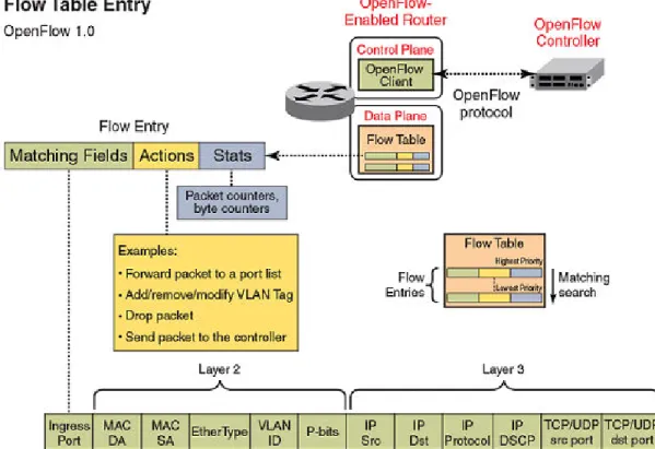
An OpenFlow-enabled router supports an OpenFlow Client (control plane software), which
communicates with an OpenFlow Controller using the OpenFlow protocol. The OpenFlow Controller runs on a server or a server cluster. OpenFlow-enabled routers support the abstraction of a flow table, which is manipulated by the OpenFlow Controller. The flow table contains flow entries. Each flow entry represents a flow (that is, packets with a given MAC address, VLAN tag, IP address, or TCP/UDP port, and so on). The flow table is sorted by flow priority, which is defined by the OpenFlow Controller. The highest priority flows are at the top of the flow table.
Incoming packets on an OpenFlow-enabled port are matched (in order of priority) against the flow entries defined for that port by the OpenFlow Controller. If the packet matches a given flow entry, the flow-matching process stops, and the set of actions defined for that flow entry are performed. Packets that don’t match any flow entry are dropped by default. The Brocade implementation of OpenFlow supports an option to send such packets to the OpenFlow Controller. Refer to Configuring the default action on page 23.
FIGURE 1 OpenFlow-enabled router
FIGURE 2 OpenFlow flow table entries
Flow table entries
The OpenFlow match rules in the following table are supported on Brocade devices for Flow table entries.
The implementation of OpenFlow supports three modes of operation when enabling OpenFlow on a port: Layer 2 mode, Layer 3 mode and Layer23 mode. Layer 2 mode supports OpenFlow matching rules based on the Layer 2 fields shown in Overview of OpenFlow on page 11, while Layer 3 mode supports the OpenFlow matching rules based on the Layer 3 fields. Layer23 mode supports the OpenFlow matching rules based on the Layer 2 and Layer 3 fields.
The Brocade ICX 6610, ICX 7750, and ICX 7450 devices support enabling ports in either Layer 2, Layer 3, or Layer23 mode. OpenFlow is supported on Breakout ports on ICX 7750.
OpenFlow match rules
TABLE 2
Match rule on Brocade device
Port enabled for Layer 2 mode Yes
Source port Yes
Source or destination MAC address Yes
These devices support either source or destination MAC address, or a combination of both source and destination MAC addresses as the match rule.
Ether type Yes
VLAN ID Yes
VLAN priority Yes
Untagged packets Yes
Port enabled for Layer 3 mode Yes
Ether type No
Source port Yes
VLAN ID Yes
VLAN priority Yes
Source IP address Yes1
Destination IP address Yes1
Protocol type Yes1
IP TOS bits Yes
TCP or UDP source port Yes1
OpenFlow match rules (Continued)
TABLE 2
Match rule on Brocade device
TCP or UDP destination port Yes Port enabled for Layer23 mode Yes
Source port Yes
Source or destination MAC address Yes
These devices support either source or destination MAC address, or a combination of both source and destination MAC addresses as the match rule.
Ether type Yes
VLAN ID Yes
VLAN priority Yes
Source IP address Yes
Destination IP address Yes
Protocol type Yes
IP TOS bits Yes
TCP or UDP source port Yes TCP or UDP destination port Yes
NOTE
For 1: Refer to the OpenFlow 1.3 specifications.
OpenFlow actions
Each OpenFlow flow table entry contains the list of actions to be performed when a packet matches the flow entry. These actions are defined by the OpenFlow Controller.
Packets that do not match any flow entry are dropped by default. The Brocade implementation of OpenFlow supports an option to send such packets to the OpenFlow Controller. Refer to Configuring the default action on page 23.
Brocade devices support the actions listed in the following table . OpenFlow actions supported on Brocade devices
TABLE 3
OpenFlow action Brocade device
Forward a packet to a set of ports Yes
OpenFlow actions supported on Brocade devices (Continued)
TABLE 3
OpenFlow action Brocade device
Drop the packet Yes
Add, modify, or remove VLAN ID or priority on a per -destination-port basis Yes Modify the IP DSCP (for a flow sending a copy of the packet to multiple
destinations, the DSCP modification must be the same for all destinations. Modifying IP DSCP is only supported on ports enabled with Layer 3 mode.)
Yes
Modify the destination MAC address Yes (It is not supported on the ICX 6450.)
Send the packet to the OpenFlow Controller (Packet In) Yes Receive the packet from the OpenFlow Controller and send it to ports (Packet Out)
Yes
OpenFlow Controller
Multiple controller connections can be used for redundancy purposes, such as when using a single controller with multiple addresses. Multiple controller connections can also be used to support active-standby controllers.
Regardless of the intended use of multiple controller connections, the Brocade device allows all the controller connections to concurrently manage the flow table. That is, flow entries in the flow table are not identified as belonging to any specific controller connection. In an active-standby controller deployment, controllers themselves must coordinate their actions and active-standby states. The Brocade device will respond to all connected controllers without distinction.
The Brocade device supports two types of controller connections (also called modes): active and passive. An active connection is one for which the Brocade device will initiate (seek) the TCP
connection to a given OpenFlow Controller address. With a passive connection, the Brocade device will passively wait for the controller to initiate (seek) the TCP connection to the Brocade device. Active mode is commonly used with production controllers, while passive mode is commonly used for testing purposes in experimental environments. Optionally, a controller connection can also use SSL
encryption.
Considerations and limitations for configuring OpenFlow
Consider the following points when you configure OpenFlow on devices:
• OpenFlow must be enabled globally on the device before you can enable interfaces for OpenFlow. • You must explicitly enable or disable OpenFlow on each interface using the CLI commands. You
cannot use a range of ports to enable OpenFlow on the interface.
• Before you can disable OpenFlow globally on the device, you must disable OpenFlow on all interfaces individually.
• Spanning Tree Protocol and other Layer 2 or Layer 3 protocols are not supported on OpenFlow-enabled ports.
• OpenFlow supports up to four concurrent sessions with a maximum of two concurrent SSL sessions.
• On hybrid OpenFlow ports, Layer 2 unicast and multicast packets will be flooded in the VLAN for protected VLANs and for unprotected VLANs in absence of flows.
• Local and normal actions defined by the OpenFlow 1.0 protocol are not supported.
• OpenFlow is an ingress feature. The local device will generate protocol messages (such as PIM, OSPF) on OpenFlow enabled-ports, if configured, but return control packets will be filtered or denied by OpenFlow default rule. Because of this limitation, the PIM neighbor (if configured) will come up on the peer, and multicast traffic will hit the OpenFlow interface in all PIM DMs, and in a PIM SM scenario in which the OpenFlow port connects to an IGMP snooping-enabled LAN that has the multicast source connected.
• On OpenFlow-enabled ports, packets that do not match any flow entry are dropped by default. Although the OpenFlow 1.0 protocol specifies sending such packets to the controller as mandatory, the Brocade implementation adopted the latest behavior defined in the OpenFlow 1.2 protocol, which specifies that such packets may be sent to the controller or may be dropped by router configuration. The Brocade implementation supports an option to send such packets to the OpenFlow Controller. Refer to Configuring the default action on page 23.
OpenFlow hybrid switch mode and OpenFlow hybrid port mode
Hybrid switch mode
The Brocade device supports enabling OpenFlow on a per-port basis, so you can choose which ports of the device will be controlled by the OpenFlow feature. Non-OpenFlow-enabled ports continue to support existing features of the device, such as IPv4 or IPv6 routing for Layer 2 switching.
NOTE
Hybrid switch mode is not supported on the ICX 6450.
Hybrid port mode
OpenFlow hybrid-enabled ports support both OpenFlow traffic forwarding and normal routing traffic forwarding. OpenFlow hybrid-enabled ports support "protected VLANs" and "unprotected VLANs". Protected VLANs are not subject to defined OpenFlow flows on the OpenFlow hybrid-enabled ports. OpenFlow flows on a hybrid-enabled port will not match any traffic on protected VLANs. Unprotected VLANs are subject to defined OpenFlow flows on the OpenFlow hybrid-enabled port. OpenFlow flows on a hybrid-enabled port are allowed to match on the traffic of unprotected VLANs.
Figure 3 shows a topology in which port 1/1 on Device-1 and port 1/4 on Device-2 are hybrid-enabled OpenFlow ports with VLAN 10 as a configured protected VLAN. By configuring a virtual ethernet (VE) interface on a protected VLAN 10 and assigning an address to route the traffic of the nodes, you are able to send protected VLAN traffic between the nodes and route the traffic as per the VE interface. Traffic flowing on other VEs created on top of other VLANs (the unprotected VLANs ) is treated as unprotected VLAN traffic and is subject to OpenFlow rules lookup. OpenFlow traffic can be forwarded through this port.
FIGURE 3 OpenFlow hybrid port mode topology
OpenFlow hybrid port mode operation
Consider Device-1 in Hybrid port mode on page 16. Ingress traffic on VLAN 10 on hybrid port 1/1 will be processed for IPv4 and IPv6 unicast routing. Traffic on other VLANs will be processed against
OpenFlow flows on port 1/1 and switched accordingly. A preconfigured number of protected VLANs can be supported for normal routing. The Spanning Tree Protocols (STP) state of these routing VLANs will be set to forwarding, as the Layer 2 protocol is not supported.
Configuring OpenFlow hybrid port mode for devices
1. Enable OpenFlow at the global configuration level. 2. Configure the OpenFlow controller.
3. Configure the system maximum OpenFlow entries. (The default is 1024.)
4. Configure the maximum OpenFlow flow-protected VLAN entries. (The default is 40.)
NOTE
System reload is required once you change the system maximum values. 5. Configure the maximum OpenFlow unprotected VLAN entries. (The default is 40.)
6. Configure the protected VLANs on the port. A maximum of 40 protected VLANs can be configured on an OpenFlow port.
7. Enable OpenFlow hybrid port mode on the desired interfaces.
8. Configure a VE interface for the interface by specifying the protected or unprotected VLAN, and add routing entries.
Capabilities and prerequisites
The following are current capabilities and prerequisites of OpenFlow hybrid port mode:
• IPv4 and IPv6 unicast routing are supported on OpenFlow protected and unprotected VLANs. • Packets tagged with a protected VLAN ID will be forwarded by IPv4 and IPv6 unicast routing, if IPv4
or IPv6 routing is configured on that VLAN. If IPv4 or IPv6 routing is not configured on that VLAN, such packets will be dropped.
• Packets tagged with an unprotected VLAN ID will be subject first to OpenFlow flows. If there is a match on an OpenFlow flow, the packet will be forwarded according to the flow actions. No further IPv4 or IPv6 routing is supported for packets that are forwarded by OpenFlow flows. If there is no match on any OpenFlow flow, the packet will be forwarded by IPv4 or IPv6 unicast routing, if IPv4 or IPv6 routing is configured on the VLAN. If IPv4 or IPv6 routing is not configured on the VLAN, those packets are either dropped or sent to the controller, per the OpenFlow configuration.
• Ports in OpenFlow hybrid port mode cannot be added as untagged ports to regular VLANs. • A port can be enabled for OpenFlow hybrid port mode only if the port is untagged in the default
VLAN.
• As routing is enabled on a port in OpenFlow hybrid port mode, OpenFlow traffic or unprotected VLAN traffic sent with the destination MAC address as the port's MAC address and matching IP route entries on the port can potentially find the VLAN and MAC address modified unless the OpenFlow rules explicitly set the VLAN and destination MAC address in the outgoing packet. • Policy-based routing (PBR) is not supported.
• Protected VLAN traffic that does not have matching IP route entries will be dropped.
• Multiple interfaces cannot be part of a VE interface created on a port in OpenFlow hybrid port mode with a protected VLAN.
• The BGP4+, OSPFv2, OSPFv3, RIP, and RIPng protocols are supported on protected VLANs. • When protected VLANs are configured but the port is not part of the VLAN, the traffic coming on the
port with the protected VLAN will be dropped. • Link aggregation is not supported.
Enabling OpenFlow hybrid port mode
Use the openflow enable command to enable or disable OpenFlow hybrid port mode on the port and the port becomes a normal port on an interface. The no form of the command disables the OpenFlow hybrid port mode on the port and the port becomes a normal port.
config-if-e10000-2/5)# openflow enable layer2 hybrid-mode
Syntax:[no] openflow enablelayer2 | layer3 | layer23 [hybrid-mode ]
Adding or deleting protected VLANs
Use openflow protected -vlans to add or delete protected VLANs on a OpenFlow hybrid port mode interface. The no form of the command deletes the configured protected VLANs from the hybrid-enabled port.
config-if-e10000-2/5)# openflow protected-vlans 10
Syntax:[no] openflow protected-vlansid1 id2...idn
VLANs can be configured individually.
NOTE
You cannot specify a VLAN range for the openflow protected-vlans command.
Displaying OpenFlow configuration
The show openflow command displays the OpenFlow configuration.
device(config)# show openflow Number of Controllers: 2 Controller 1:
Connection Mode: passive, TCP, Listening Address: 0.0.0.0 Connection Port: 6633 Connection Status: SSL Connection :False No TCP connection found. Controller 2:
Connection Mode: active, TCP, Controller Address: 10.20.101.199 Connection Port: 23
Connection Status:
Local IP address:port <-> Remote IP address:port TCP state RcvQue RxBuffe SendQue TxBuffe
10.20.178.73 8807 10.20.101.199 23 ESTABLISHED 0 0 0 0
SSL Connection :False Match Capabilty:
L2: Port, Source MAC, Destination MAC, Ether type, Vlan, Vlan PCP
L3: Port, Vlan, Vlan PCP, Source IP, Destination IP, IP Protocol, IP TOS, IP Src Port, IP Dst Port
Normal Openflow Enabled Ports: e2/1 Hybrid Mode ports Protected Vlan-IDs e4/1 (100,101,102,103) e7/2 (200)
Default action: drop
Maximum number of flows allowed: 4096
Maximum number of Protected Vlans allowed: 2048
Configuring OpenFlow
You can enable OpenFlow on an interface with Layer23 option in order to support Layer 2 and Layer 3 flows on that interface. Layer23 option supports the OpenFlow hybrid port mode also. Configured with the Layer23 option, the controller can configure flows with Layer 2 and Layer 3 parameters together. A flow can contain the following fields, Ingress port, MAC DA, MAC SA, Ethertype, VLAN ID , P-bits, IP Src, IP Dst, IP protocol, and IP DSCP.
By default, OpenFlow is disabled on Brocade devices. You must first enable OpenFlow on the device before you can configure the parameters on the device.
Enabling OpenFlow on devices
After you enable OpenFlow on the device, you can enable OpenFlow on specific interfaces and configure additional OpenFlow parameters.
To enable OpenFlow, enter the following command:
device(config)# openflow enable ofv100
Syntax:[no] openflow enableofv100
The ofv100 keyword specifies the OpenFlow protocol version supported. Use the no form of the command to disable OpenFlow feature on the device.
NOTE
You must disable OpenFlow on all interfaces individually before you can disable OpenFlow globally on the device.
Enabling OpenFlow on a specified interface
After you have enabled the OpenFlow feature on the device, you can enable OpenFlow on specific interfaces.
NOTE
You can enable OpenFlow on an interface only after you have enabled OpenFlow globally on the device. In addition, you must use individual CLI commands to enable OpenFlow on each interface. You cannot specify a range of ports when enabling OpenFlow on them.
To enable OpenFlow on specific interface, enter the following command:
device(config-if-e1000-1/1)# openflow enable layer2
Syntax:[no] openflow enable [layer2 | layer3 | layer23 [ hybrid-mode ] ]
You can specify Layer 2 or Layer 3 or both layers (as Layer23 matching mode) in OpenFlow hybrid port mode to be supported on the interface. By default, interfaces on these devices support Layer 2 matching mode. If you enable Layer 2 matching mode on the specified interface, only Layer 2 matching fields are supported on that interface.
To disable OpenFlow on the interface, use no form of the command.
Flow validation
The following validations are required before programming flows on a Layer23 port: • When IP fields exist in rule, then the ETH_TYPE must be 0x800.
• IPv6 rules are supported on the Layer23 port. (But IPv6 destination match in Layer23 mode is not supported.)
Flow action
OpenFlow actions are not changed for Layer23 support. All actions currently supporting Layer 2 or Layer 3 flows will continue to be supported. Actions currently supported are listed separately for different devices.
On Brocade devices:
When a matching flow entry is found, a set of actions can be applied for processing the packet. The system supports the following actions:
• Forward a packet to a port. • Forward a packet to a set of ports. • Forward a packet to a controller.
• Forward a packet received from a controller to a port or set of ports. • Drop the packet.
• Keep, add, modify, or remove the VLAN ID or the VLAN priority. Modifying the VLAN ID per port is also supported (each destination port can send a packet with a different VLAN ID for the same matching rule).
• Modify the destination MAC address for Layer 2 flows.
Connecting to an OpenFlow controller
To connect to anOpenFlow controller in active mode, enter the following command:
device(config)# openflow controller ip-address 10.2.3.4
Syntax:[no] openflow controller ip-addressip-address [ no-ssl ] [ portport ]
The ip-address variable specifies the IP address of the OpenFlow Controller. By default, the connection with the Controller uses SSL encryption, but you can optionally disable SSL encryption using the no-ssl keyword. By default, the OpenFlow connection uses TCP port 6633, but you can specify another port using the port parameter.
Use the no form of the command to remove the specified OpenFlow Controller connection. To connect to an OpenFlow controller in the passive mode, enter the following command:
device(config)# openflow controller passive no-ssl
Syntax:[no] openflow controller passive no-ssl [ ip-addressip-address ] [ portport ]
You can optionally specify the TCP port to be used for the connection. By default, the device accepts the connection from a controller with any IP address. However, you can provide an IP address to limit which controller can connect to the device.
Use the no form of the command to remove a passive connection. Passive mode connections are intended for testing environments and not recommended for production environments.
Setting up SSL encryption for controller connections
By default, a connection to the controller uses SSL encryption. To set up SSL encryption, copy the SSL certificate and SSL client private key from the remote machine where you generated these into the device's flash using the following commands:
device(config# copy tftp flash <remote ip> <remote file> client-certificate device(config# copy tftp flash <remote ip> <remote file> client-private-key
Syntax: copy tftp flashremoteip | remotefileclient-certificate Syntax: copy tftp flashremoteip | remotefileclient-private-key
The remote ip variable specifies the IP address of the remote machine from which the SSL client certificate is being copied.
NOTE
SSL is not supported on passive controller connections.
The remote file variable specifies the file name of the client certificate in the first command, and the client private key in the second command.
For each controller, you must enter both the commands. The device can store up to three SSL certificates and client private keys. If you remove a controller connection, you will need to delete the
SSL certificates and client private keys from the device’s flash memory using the monitor mode commands.
Disabling an SSL client
You can disable the SSL client within the device using the following command:
device# ip ssl client disable
Syntax:[no] ip sslclientdisable
After you disable an SSL client in the device, the corresponding controller connection that used SSL encryption will fail. However, you can re-enable the controller connection by removing the SSL encryption option from the controller connection. Use the no-ssl option in the openflow controller ip-address ip-ip-address command to disable SSL encryption in the connection.
To re-enable SSL client in the device, use the no form of ip ssl client disable command.
Configuring multiple controller connections
Brocade devices support up to three controller connections. You can configure these connections with active or passive modes, in any combination, such as all active, all passive, or some active and some passive. Each connection requires its own separate command. You can remove any of the
connections using the no form of the openflow controller ip-address command. The following example shows how you configure three connections.
device(config)# openflow controller ip-address 10.2.3.4 no-ssl port 6635 device(config)# openflow controller ip-address 10.2.3.5 no-ssl
device(config)# openflow controller passive no-ssl ip-address 10.2.3.6
Configuring the system parameters for OpenFlow
You can specify the limit for OpenFlow flow table entries in the flow table using the following command:
device(config)# system-max openflow-flow-entries 304
Syntax:system-max openflow-flow-entrieslimit
Use the limit variable to specify the maximum number of flow table entries. The range is from 0 through 12000. The default is 1024 flow table entries.
Setting the system maximum
The maximum number of flows supported per device in a stack is 3000 in Layer 2 and Layer 3 modes and 1500 in the case of Layer23 mode or Layer 3 mode (with IPv6 matching).
The system-max openflow-pvlan-entries command sets the CAM size of OpenFlow protected VLAN entries for the device. By default, this value is set to 128.
device(config)# system-max openflow-pvlan-entries 200
Syntax:system-max openflow-pvlan-entriesvalue
The value variable represents the number of port and protected VLAN combination entries that can be configured in the system. The range is from 0 through 256. After using this command, you must reload the system.
The system-max openflow-unprotectedvlan-entries command sets the CAM size of OpenFlow unprotected VLAN entries for the device. By default, this value is set to 128.
device(config)# system-max openflow-unprotectedvlan-entries 100
Syntax:system-max openflow-unprotectedvlan-entriesvalue
The value variable represents the number of port and unprotected VLAN combination entries that can be configured in the system. The range is from 0 through 256. After using this command, you must reload the system.
Configuring the default action
By default, the device drops packets that do not match any of the programmed flows. However, you can configure a device-level option to forward the packets to the controller instead of dropping them. This is an optional configuration. If this option is not configured, packets that do not match any flow entries on a port are dropped. When sending a packet to the controller, a copy of the packet is sent to each of the configured controller connections.
To enable the default action, enter the following command:
device(config)# openflow default send-to-controller
Syntax:[no] openflow defaultsend-to-controller
Packets that match a flow entry on a port are processed according to the action specified and are not affected by this setting. Use the no form of the command to set the default action to drop such packets instead.
Displaying the OpenFlow status on the device
After enabling or disabling OpenFlow on a device, you can verify the configuration using any of the
show commands.
Displaying Openflow show
The show OpenFlow command displays the OpenFlow configuration. It includes the configured unprotected VLANs as well.
device(config)# show openflow Administrative Status: Enabled SSL Status: Enabled Controller Type: OFV 100 Number of Controllers: 1 Controller 1:
Connection Mode: passive, TCP, Listening Address: 0.0.0.0 Connection Port: 6633
Connection Status: TCP_LISTENING Match Capability:
L2 : Port, Source MAC, Destination MAC, Ether type, Vlan, Vlan PCP
L3 : Port, Vlan, Vlan PCP, Ethertype(IP,ARP,LLDP), Source IP, Destination IP, IP Protocol, IP TOS, IP Src Port, IP Dst Port
L23: All
Normal Openflow Enabled Ports: Openflow Hybrid Interfaces:
e1/1
Protected VLANs : None
Unprotected VLANs : 2, 3, 4, 5, 6, 7, 8, 9, 10, 11 ... ... 3994, 3995, 3996, 3997, 3998, 3999, 4000, 4001, 4011,
Protected VLANs : None Unprotected VLANs : 4010, Default action: drop
Maximum number of flows allowed: 65536 Active flow: 0
Maximum number of Protected Vlans allowed: 2048 Maximum number of Unprotected Vlans allowed: 4096 Total number of Unprotected Vlans: 4002
Syntax:show openflow
Displaying the OpenFlow status
If OpenFlow is enabled on a device, you can get a detailed report of the OpenFlow status on that device.
Displaying the configured connections to controllers
Use the show openflow command to display the OpenFlow configuration, including the configured connections to controllers on the device.
device(config)# show openflow Administrative Status: Enabled Controller Type: OFV 100 Number of Controllers: 3 Controller 1:
Connection Mode: active, TCP Controller Address: 10.25.128.243 Connection Port: 6633
Controller 2:
Connection Mode: active, TCP Controller Address: 10.25.128.242 Connection Port: 6633
Controller 3:
Connection Mode: passive, TCP Listening Address: 0.0.0.0 Connection Port: 6633 Match Capabilty:
Port, Destination MAC, Vlan, Vlan PCP Openflow Enabled Ports: e1/1 e1/2
Output fields for the show openflow command
TABLE 4
Field Description
Administrative Status Indicates the administrative status of OpenFlow on the device.
Controller Type Indicates the OpenFlow protocol version that is supported on the device. Number of Controllers Lists the number of controller connections configured on the device. Brocade
devices support up to three concurrent controller connections.
Connection mode Indicates the mode of the controller connection configured. You can configure active or passive connection to controllers. An active connection is initiated by the device. In a passive connection, the device is in the listening mode, and accepts requests from controllers. If the optional controller address is not specified, any controller can establish a connection with the device in the passive mode. Refer to
Connecting to an OpenFlow controller on page 21. Controller address Indicates the address of the specified controller.
Output fields for the show openflow command (Continued)
TABLE 4
Field Description
Connection port Indicates the TCP port that is used for connection to the controller. By default, port 6633 is used.
Match capability Specifies the matching rules supported.
OpenFlow enabled ports Lists the ports on the device that are enabled for OpenFlow. OpenFlow hybrid mode ports Indicates the VLAN IDs.
Default Action Indicates the default action for packets that do not match any configured flows. By default, such packets are dropped. However, you can configure these packets to be sent to the controller by using the openflow default send-to-controller command.
Maximum Number of Flows Allowed
Indicates the maximum number of flows allowed on the device that is configured by using the system-max openflow-flow-entries command.
Displaying the data path ID of the device
OpenFlow associates a globally unique data path ID to be used by the controller to distinguish
OpenFlow devices on a network. To display the data path ID assigned to the device, enter the following command:
device(config)# openflow datapath-id datapath-id# 0000001bedb3d0c0
Syntax:openflow datapath-id
Displaying the OpenFlow flows
You can display the OpenFlow flows that are configured on the device and their statistics by using the following command:
device(config)# show openflow flows eth 1/2
Syntax:show openflow flows [ ethx/y/z ] [ flowid ]
The show openflow flows command shows all the flows configured in the system flow table. If you specify the interface, all the flows configured in the system for that interface are displayed. You can use the optional flowid keyword to display the flows configured in the system and associated with the specified flow ID.
device(config)# show openflow flows Flow ID: 1 Priority: 32768 Status: Active Rule:
In Port: e1/1
In Vlan: Tagged[100]
Vlan Mask: 0xfff Vlan PCP: 3
Source Mac: 0000.0000.0001 Destination Mac: 0000.0000.0002
Source Mac Mask: ffff.ffff.ffff Destination Mac Mask: ffff.ffff.ffff
Source IP: 1.1.1.0 Subnet IP: 255.255.255.0 Destination IP: 2.2.2.0 Subnet IP: 255.255.255.0 IP TOS: 8
IP Protocol: 17
IP Protocol Source Port: 10000 IP Protocol Destination Port: 80 Cookie: abcdef
Cookie Mask: 0xfffff Instruction: Apply Action Action: FORWARD
Out Port: e1/2, Tagged, Vlan: 10 Action: FORWARD
Out Port: e1/3, Tagged, Vlan: 20 Statistics:
Total Pkts: 0 Total Bytes: 0
Output fields for the show openflow flows command
TABLE 5
Field Description
Total Number of Flows The total number of flows on the device. Total number of data packets
sent to controller
The number of packets sent to the controller.
Total number of data bytes sent to controller
The number of bytes sent to the controller.
Flow ID An identifier for each flow. You can use the flow ID from this output to display flow-specific details.
Priority The priority of the flow set by the controller when the flow is added, in the range 0 to 65536. If the priority value was not specified, the Brocade device will assign the default value, 32768.
Status Indicates whether the flow is configured correctly in the device. A correctly configured flow will have its status as active.
Rule Here, the destination MAC Address Mask of FFFF.FFFF.FFFF indicates that only packets exactly matching the specified destination MAC address will be
forwarded.
Statistics Indicates the counter of packets and bytes.
Purge-time for OpenFlow
You can configure the maximum time before stale flows are purged from the OpenFlow flow table after a switch-over, fail-over, or operating system upgrade. The no form of this command sets the purge timer time to its default value.
The valid range is from 1 through 600. The default is 240 seconds.
You may not need to change the value of the OpenFlow purge timer for normal circumstances. If you anticipate delay in learning the flows from controller after switch-over, you can configure a larger value for the OpenFlow purge timer.
The following example shows how to set the OpenFlow purge timer:
device(config)# openflow purge-time 500 device(config)# no openflow purge-time 350
Syntax:openflow purge-timeseconds Syntax:no openflow purge-timeseconds
Administrating OpenFlow
Clearing the OpenFlow statistics
You can clear the flow statistics for all flows or, optionally, for a specified flow. Only the counters of packets and bytes (when applicable) are cleared; none of the other flow table entries are affected. To clear flow counters, enter the following command:
device(config)# clear statistics openflow
Syntax:clear statistics openflow [ flow-id ]
The flow-id keyword, if specified, clears only the counters for the specified flow. Use the show openflow flows command to obtain flow IDs.
Deleting the OpenFlow flows
When an individual OpenFlow rule or all flows in the flow table need to be deleted, you can use the
clear openflow command. Use this command to delete a single OpenFlow rule based on a Flow ID or delete all flows in the flow table.
device# clear openflow flowid 6
Syntax:clear openflowflowidflow-id| all
The flowidflow-id parameter deletes a single OpenFlow rule with the given flow ID. The all keyword deletes all flows in the flow table. The command will delete the rule irrespective of the state it is in (ACTIVE, PENDING_ADD, PENDING_MODIFY, or PENDING_DELETE). The same rule can be added again later from the controller if needed.
Show tech
The show tech-support openflow command captures the output of multiple show commands at one time, to be used for diagnostic purposes.
device# show tech-support openflow
Syntax:show tech-supportopenflow
• show openflow datapath-id
• show openflow controller
• show openflow interface
• show openflow flows
• show versions
• show interfaces
• show statistics
• show running-config
• show logging
• show save
OpenFlow configuration considerations
After you enable OpenFlow on a device, you can configure, generate, and monitor flows on the ports configured on the device from a controller on OpenFlow-enabled ports. The Brocade device flow table is entirely under the control of the OpenFlow Controller.
The OpenFlow Controller supports Administratively down ( OFPPC_PORT_DOWN) through a Port Modification Message.
Behavior of ports and devices
• Ports that are enabled for OpenFlow cannot take part in any of the normal operations of the device, such as routing and Layer 2 forwarding. However, after OpenFlow is disabled on a port, the port can resume normal operations. This does not require disabling OpenFlow globally on the device. • The flow table content is not cleared when the connection to a controller is lost. The device will
continue to forward traffic according to the flow entries defined in the flow table even in the absence of a controller connection.
• The flow table entries within the device are cleared when the device is reset.
• Flow table entries associated with a port are maintained when a port goes down. When the port comes back up, those flow entries are restored on the port. Flow entries are removed only with an explicit command from the controller.
• When OpenFlow is disabled globally on the device using the no openflow enable command, the flow table in the device is cleared. However, before you can disable OpenFlow globally on the device, you must disable OpenFlow on all interfaces individually.
• When a controller tries to add a flow to the device with the same priority, rule, and action as a flow that exists in the flow table, the flow statistics are cleared (the system does not add a new flow). The following table summarizes the behavior for similar flows being successively added.
Flow table behavior when flows similar to existing ones are added
TABLE 6
Priority Rule Action Device behavior
Same Same Same Clear flow statistics
Same Same Different • Update the action list
• Clear the statistics
Flow table behavior when flows similar to existing ones are added (Continued)
TABLE 6
Priority Rule Action Device behavior
Same Different Same Create new flow
Same Different Different Create new flow
Different Same Same Create new flow
Different Same Different Create new flow
Removing an OpenFlow configuration from a device
In general, to remove OpenFlow from the device and make it a non-OpenFlow device, complete the following steps:
1. Disable OpenFlow on the ports where it is enabled. 2. Disable OpenFlow on the device globally.
3. (Optional) Set the maximum number of flows to zero using the system-max openflow-flow-entries
0 command.
4. Reload the device.
OpenFlow 1.3
● Overview of OpenFlow 1.3...31
● Group table... 44
● Enqueue...47
● Metering... 48
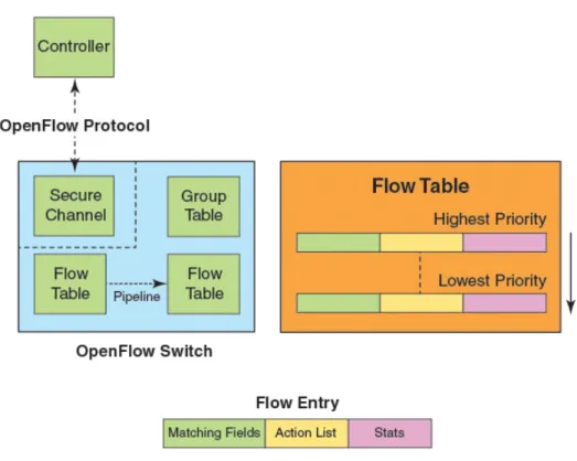
Overview of OpenFlow 1.3
An OpenFlow switch maintains one or more flow tables, which are used for packet processing. The switch performs the actions listed in the table entry corresponding to the matched flow.
The OpenFlow Controller manages the OpenFlow switch using the OpenFlow Protocol. The OpenFlow Controller can add, delete, or modify flows by getting statistics for ports and flows and other information using the OpenFlow Protocol.
FIGURE 4 OpenFlow 1.3 architecture
Each flow table maintained in a switch, consists of flow entries sorted by the flow priority. Highest priority flows are at the top of the flow table. Incoming packets are matched against the flow entries starting from the highest priority flow. If there is a match, then flow matching stops, and the set of actions for that flow entry performed. The packets that don't match any flow entry, are either dropped, or sent to the controller.
• Flow tables • Group table • Meter table
FIGURE 5 OpenFlow 1.3 flow table entries
The incoming packets are matched against the multiple tables in the pipeline.
FIGURE 6 Pipeline processing
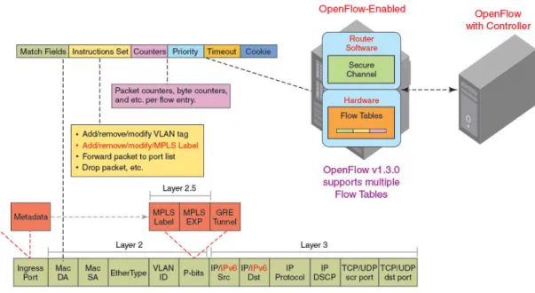
Flow table entries
Each flow table entry contains the fields described in the following table. Flow table entries
TABLE 7
Field Description
Match fields The match fields consist of ingress ports, packet header fields, and metadata from a previous flow table
Priority Matching precedence of the entry
Counters Statistics for matching packets
Instructions Action set or pipeline processing
Cookie Opaque data sent by the OpenFlow Controller
FastIron release 08.0.30 supports the OpenFlow match fields in the following table. OpenFlow match fields
TABLE 8
Match field ICX 6610 ICX 6450 (mixed Stack)
Prerequisite Description
L2 L3 L23 L2 L3 L23
OXM_OF_IN_PORT Yes Yes Yes Yes Yes Yes IN PORT present
Ingress port. Numerical representation of incoming port, starting at 1. This may be a physical or switch-defined logical port. OXM_OF_IN_PHY
_PORT
Yes Yes Yes Yes Yes Yes None Physical port. In OFP_PACKET_IN messages, underlying physical port, when packet received on a logical port. OXM_OF_ETH_DST Yes No Yes Yes Yes Yes None Ethernet destination MAC
address
OXM_OF_ETH_SRC Yes No Yes Yes No Yes None Ethernet source MAC address
OXM_OF_ETH_TYPE Yes No Yes Yes No Yes None Ethernet type of the OpenFlow packet payload, after VLAN tags.
OXM_OF_VLAN_VID Yes Yes Yes Yes Yes Yes None VLAN-ID 802.1Q header OXM_OF_VLAN_PCP Yes Yes Yes Yes Yes Yes None VLAN-PCP 802.1Q header OXM_OF_IP_DSCP No Yes Yes No Yes Yes ETH_TYPE=
0x0800
Diff Serv Code Point (DSCP). Part of the IPv4 TOS field or the IPv6 Traffic Class field. OXM_OF_IP_PROTO No Yes Yes No Yes Yes ETH_TYPE=
0x0800
IPv4 or IPv6 protocol number OXM_OF_IPV4_SRC No Yes Yes No Yes Yes ETH_TYPE=
0x0800
IPv4 source address. It can use subnet mask or arbitrary bit mask.
OpenFlow match fields (Continued)
TABLE 8
Match field ICX 6610 ICX 6450 (mixed Stack)
Prerequisite Description
L2 L3 L23 L2 L3 L23
OXM_OF_IPV4_DST No Yes Yes No Yes Yes ETH_TYPE= 0x0800
IPv4 destination address. It can use subnet mask or arbitrary bit mask. OXM_OF_TCP_SRC No Yes Yes No Yes Yes IP PROTO =
6
TCP source port OXM_OF_TCP_DST No Yes Yes No Yes Yes IP PROTO =
6
TCP destination port OXM_OF_UDP_SRC No Yes Yes No Yes Yes IP PROTO =
17
UDP source port OXM_OF_UDP_DST No Yes Yes No Yes Yes IP PROTO =
17
UDP destination port OXM_OF_SCTP_SRC No Yes Yes No Yes Yes IP PROTO =
132
SCTP source port OXM_OF_SCTP_DST No Yes Yes No Yes Yes IP PROTO =
132
SCTP destination port OXM_OF_ICMPV4
_TYPE
No Yes Yes No Yes Yes IP PROTO = 1
ICMP type
OXM_OF_ICMPV4 _CODE
No Yes Yes No Yes Yes IP PROTO = 1
ICMP code
OXM_OF_ARP_SPA No Yes Yes No Yes Yes ETH_TYPE= 0x0806
IPv4 source address in the ARP payload. It can use subnet mask or arbitrary bit mask.
OXM_OF_ARP_TPA No Yes Yes No Yes Yes ETH_TYPE= 0x0806
IPv4 destination address in the ARP payload.. It can use subnet mask or arbitrary bit mask.
OXM_OF_IPV6_SRC No Yes Yes No Yes Yes ETH_TYPE= 0x86dd
IPv6 source address. It can use subnet mask or arbitrary bit mask.
OXM_OF_IPV6_DST No Yes No No Yes No ETH_TYPE=
0x86dd
IPv6 destination address. It can use subnet mask or arbitrary bit mask.
OpenFlow match fields for the ICX 7750 and ICX 7450
TABLE 9
Match field ICX 7750 ICX 7450 Prerequisite Description
L2 L3 L23 L2 L3 L23
OXM_OF_IN_PORT Yes Yes Yes Yes Yes Yes IN PORT present
Ingress port. Numerical representation of incoming port, starting at 1. This may be a physical or switch-defined logical port.
OpenFlow match fields for the ICX 7750 and ICX 7450 (Continued)
TABLE 9
Match field ICX 7750 ICX 7450 Prerequisite Description
L2 L3 L23 L2 L3 L23 OXM_OF_IN_PHY
_PORT
Yes Yes Yes Yes Yes Yes None Physical port. In OFP_PACKET_IN messages, underlying physical port, when packet received on a logical port. OXM_OF_ETH_DST Yes No Yes Yes Yes Yes None Ethernet destination MAC
address
OXM_OF_ETH_SRC Yes No Yes Yes No Yes None Ethernet source MAC address
OXM_OF_ETH_TYPE Yes No Yes Yes No Yes None Ethernet type of the OpenFlow packet payload, after VLAN tags.
OXM_OF_VLAN_VID Yes Yes Yes Yes Yes Yes None VLAN-ID 802.1Q header OXM_OF_VLAN_PCP Yes Yes Yes Yes Yes Yes None VLAN-PCP 802.1Q header OXM_OF_IP_DSCP No Yes Yes No Yes Yes ETH_TYPE=
0x0800
Diff Serv Code Point (DSCP). Part of the IPv4 TOS field or the IPv6 Traffic Class field. OXM_OF_IP_PROTO No Yes Yes No Yes Yes ETH_TYPE=
0x0800
IPv4 or IPv6 protocol number OXM_OF_IPV4_SRC No Yes No No Yes Yes ETH_TYPE=
0x0800
IPv4 source address. It can use subnet mask or arbitrary bit mask.
OXM_OF_IPV4_DST No Yes Yes No Yes Yes ETH_TYPE= 0x0800
IPv4 destination address. It can use subnet mask or arbitrary bit mask. OXM_OF_TCP_SRC No Yes Yes No Yes Yes IP PROTO =
6
TCP source port OXM_OF_TCP_DST No Yes Yes No Yes Yes IP PROTO =
6
TCP destination port OXM_OF_UDP_SRC No Yes Yes No Yes Yes IP PROTO =
17
UDP source port OXM_OF_UDP_DST No Yes Yes No Yes Yes IP PROTO =
17
UDP destination port OXM_OF_SCTP_SRC No Yes Yes No Yes Yes IP PROTO =
132
SCTP source port OXM_OF_SCTP_DST No Yes Yes No Yes Yes IP PROTO =
132
SCTP destination port OXM_OF_ICMPV4
_TYPE
No Yes Yes No Yes Yes IP PROTO = 1
ICMP type
OXM_OF_ICMPV4 _CODE
No Yes Yes No Yes Yes IP PROTO = 1
ICMP code
OpenFlow match fields for the ICX 7750 and ICX 7450 (Continued)
TABLE 9
Match field ICX 7750 ICX 7450 Prerequisite Description
L2 L3 L23 L2 L3 L23
OXM_OF_ARP_SPA No No No No Yes Yes ETH_TYPE=
0x0806
IPv4 source address in the ARP payload. It can use subnet mask or arbitrary bit mask.
OXM_OF_ARP_TPA No No No No Yes Yes ETH_TYPE=
0x0806
IPv4 destination address in the ARP payload.. It can use subnet mask or arbitrary bit mask.
OXM_OF_IPV6_SRC No Yes No No Yes No ETH_TYPE=
0x86dd
IPv6 source address. It can use subnet mask or arbitrary bit mask.
OXM_OF_IPV6_DST No Yes Yes No Yes Yes ETH_TYPE= 0x86dd
IPv6 destination address. It can use subnet mask or arbitrary bit mask.
OpenFlow instructions
Each flow entry has a set of instructions that are executed when the packet matches the entry. The instruction set associated with each flow entry can have a maximum of one instruction of each type.Following table shows the actions supported on different Brocade devices.
Actions for flow table instruction
TABLE 10
Actions Description ICX 6610 ICX 6450 (Mixed stack)
Write-Action actions ( Req )
Adds or overwrites specified actions to the action set.
Yes Yes
Apply-Actions actions
Applies the specified actions immediately.
Yes Yes
Clear-Actions actions Clears all the actions in the action set.
Yes Yes
Meter meter-id Directs the packet to the specified meter.
Yes No
Goto -Table next-table-id ( Req )
Indicates the next table in pipeline processing.
No No
Write-Metadata metadata/mask
Writes the metadata field from the mask.
No No
Output (Req) Forwards the packet to a specified OpenFlow port. If out-port is Controller, then the packet will be sent as packet-in message.
Yes Yes
Drop (Req) No explicit drop action. Packet with empty action set should be dropped.
Yes Yes
Group Processes the packet through the specified group.
Yes No
Actions for flow table instruction (Continued)
TABLE 10
Actions Description ICX 6610 ICX 6450 (Mixed stack)
Set field Modifies the values of the packet header based on the field type.
Yes Yes
Push-Tag/ Pop-Tag Adds and removes tag (newly inserted tags are always the outermost tags).
Yes Yes
Set-Queue Enqueues the packet to a specific queue on the outgoing port.
Yes (The priority of the queue is honored in line with the QoS mechanism configured on the switch.)
Yes (The priority of the queue is honored in line with the QoS mechanism configured on the switch.)
Decrement TTL Decrements the TTL value by 1. Yes1 Yes1
Actions for flow table instruction for ICX 7750 and ICX 7450
TABLE 11
Actions Description ICX 7750 ICX 7450
Write-Action actions ( Req )
Adds or overwrites specified actions to the action set.
Yes Yes
Apply-Actions actions Applies the specified actions immediately.
Yes Yes
Clear-Actions actions Clears all the actions in the action set. Yes Yes Meter meter-id Directs the packet to the specified
meter.
Yes Yes
Goto -Table next-table-id ( Req )
Indicates the next table in pipeline processing.
No No
Write-Metadata metadata/mask
Writes the metadata field from the mask.
No No
Output (Req) Forwards the packet to a specified OpenFlow port. If out-port is Controller, then the packet will be sent as packet-in message.
Yes Yes
Drop (Req) No explicit drop action. Packet with empty action set should be dropped.
Yes Yes
Group Processes the packet through the specified group.
Yes Yes
Set field Modifies the values of the packet header based on the field type.
Yes Yes
Push-Tag/ Pop-Tag Adds and removes tag (newly inserted tags are always the outermost tags).
Yes Yes
Set-Queue Enqueues the packet to a specific queue on the outgoing port.
Yes Yes
Decrement TTL Decrements the TTL value by 1. Yes1 Yes1
NOTE
1: This action behaves differently on different Brocade devices. This action must be accompanied with a DMAC modification. In addition, the incoming traffic destination MAC address must be equal to the switch's MAC address for this action to work. Otherwise, the traffic will be dropped.
NOTE
1: This action behaves differently on different Brocade devices.
The set fields in the following table are supported for OpenFlow instructions. The set field action is used to set the value in the header field.
Supported set field action
TABLE 12
Set field ICX 6610 ICX 6450 (mixed stack) Description
OXM_OF_ETH_DST Yes No Ethernet destination MAC address (A
maximum of 600 flows can be configured with this action)
OXM_OF_ETH_SRC No No Ethernet source MAC address
OXM_OF_ETH_TYPE No No Ethernet type of the OpenFlow packet
payload after VLAN tags.
OXM_OF_VLAN_VID Yes Yes VLAN-ID 802.1Q header (The output port
must be a part of the VLAN that the flow is trying to set)
OXM_OF_VLAN_PCP Yes Yes VLAN-PCP 802.1Q header
OXM_OF_IP_DSCP Yes Yes Diff Serv Code Point (DSCP). Part of the
IPv4 ToS field or the IPv6 Traffic Class field.
Supported set field action for ICX 7750 and ICX 7450
TABLE 13
Set field ICX 7750 ICX 7450 Description
OXM_OF_ETH_DST Yes Yes Ethernet destination MAC address (A
maximum of 600 flows can be configured with this action)
OXM_OF_ETH_SRC Yes Yes Ethernet source MAC address
OXM_OF_ETH_TYPE No No Ethernet type of the OpenFlow packet
payload after VLAN tags.
OXM_OF_VLAN_VID Yes Yes VLAN-ID 802.1Q header (The output port
must be a part of the VLAN that the flow is trying to set)
OXM_OF_VLAN_PCP Yes Yes VLAN-PCP 802.1Q header
OXM_OF_IP_DSCP Yes Yes Diff Serv Code Point (DSCP). Part of the
IPv4 ToS field or the IPv6 Traffic Class field.
OXM_OF_IP_ECN Yes Yes Modify ECN bits of the IP header.
OpenFlow actions
Each flow has a set of instructions that are executed when the packet matches the flow as per OpenFlow 1.3 specifications. Each flow can have a maximum of one instruction of each type.
A switch can reject a flow entry, if it is unable to execute the instructions associated with the flow entry. In this case, the switch returns an unsupported flow error. Flow tables may not support every match, every instruction, or every action.
Instructions for OpenFlow actions
TABLE 14
Instruction Description
actions Adds specified actions to the action set
next-table-id Indicates the next table in pipeline processing (One table is supported.)
meter-id Directs the packet to the specified meter
apply-actions Applies the specified actions immediately. The packet is modified and subsequent matching in the pipeline is done on the modified packet.
clear-actions Clears all the actions in the action set
write-metadata Writes the metadata field from the mask
Brocade devices may support the actions listed in the following table. OpenFlow actions supported on Brocade devices
TABLE 15
OpenFlow action ICX 6610 ICX 6450 (Mixed stack)
ICX 7750 ICX 7450
Process the packet through the specified group
Yes No Yes Yes
Add and remove tag Yes Yes Yes Yes
Add newly inserted tags always as the outermost tags
Yes Yes Yes Yes
No explicit drop action. Packet with empty action set should be dropped.
Yes Yes Yes Yes
Modify the values of the packet header based on the field type
Yes Yes Yes Yes
Modify the TTL value No No No No
Set the queue ID for the packet Yes Yes Yes Yes
Prerequisite for OpenFlow actions
The following prerequisites apply to the OpenFlow actions.
Decrement TTL
• DMAC action is required, otherwise error is sent to controller.
• DMAC in the packet should be router-mac of the device. This is not enforced as DMAC of the forwarding packet is unknown.
• SMAC is modified to router-mac.
• VLAN header will be stripped after the action.
• VLAN modification is supported (Push VLAN is not supported for tagged packets).
Multiple ports
• When action is to send the packets on multiple ports then packet modification is not supported and an error message will be generated if there are any actions.
Send to controller action
• Send to Controller action can be combined with single port or multiple port action. • Send to controller action with single port does support packet modification. • Send to controller action with multiple ports does not support packet modification.
VLAN modification
• The port on which the packet is to be forwarded with VLAN modification, needs to be part of the VLAN to be configured and the port has to be added as tagged.
NOTE
This is applicable only for ICX 6610 & ICX 6450.
Destination MAC modification
• VLAN header will be stripped after DMAC modification.
• VLAN modification is supported (Push VLAN is not supported for tagged packets).
Scaling considerations
These are the scaling considerations and limitations for the flows and CAM partitions. These considerations are for ICX 6610 and ICX 6450 in mixed stack only.
• The TCAM size is 3K. So a maximum of 3K rules can be stored.
• There is no TCAM partition for OpenFlow, so regular ACLs like IP ACL, IPv6 ACL, MAC filters, system ACLs share the common resources. If OpenFlow is not able to add the flow to TCAM, then an error message will be sent to the controller.
• The TCAM size is 3K per packet processor. A 48-port unit has 2 packet processors so a maximum of 6K flows can be supported.
• Generic flows are replicated to all OpenFlow ports. So for 10 OpenFlow ports, 10 TCAM rules are used.
• In case of stacking, the number of rules will be additive.
• Interface in Layer 2 mode consumes 1 TCAM entry, so it can support up to 3K flows. • Interface in Layer 3 mode consumes 1 TCAM entry, so it can support up to 3K flows. • Interface in Layer23 mode consumes 2 TCAM entries, so it can support up to 1500 flows. • Each protected VLAN or unprotected VLAN requires 1 TCAM entry per interface.
Scaling numbers for flows
Few rules are used by system to trap or to set QoS for control packets and security features. Brocade devices support up to 3K flows. OpenFlow flows are categorized as 3 types which is configured per interface.