ISSN 1991-8178
Corresponding Author: P. Ilanchezhian, Associate Professor, Department of IT, Sona College of Technology, Salem
New Design Approach and Implementation of Minterm Generator Circuit using QCA
1
P. Ilanchezhian,
2Dr. R.M.S. Parvathi
1
Associate Professor, Department of IT, Sona College of Technology, Salem
2Principal, Sengunthar College of Engineering, Tiruchengode,
Abstract: Resent days digital systems play a outstanding role in a large amount of the commercial, industrial, and scientific applications. In this paper, a successful approach to design and implementation of minterm generato r circuit using quantum dot cellular automata is presented in nanotechnology. This paper we use three input majority gate is the fundamental component of the QCA circuit implementation. The proposed minterm generator circuit is designed and replicated using quantum dot cellular automata designer tool for the two input levels and this simulator tool are further useful for construct a multifarious minterm generator input levels. The proposed structure of minterm generator circuit needed only a smaller amount of majority gate functions compared to earlier structures because of its three input levels.
Key words: Digital Circuits, Quantum Dot Cellular Automata, Majority gate, minterm generator.
INTRODUCTION
A digital circuit was useful in most of the applications like digital telephones, digital television, digital versatile discs, digital cameras, handheld devices, and digital computers. The digital computers are an important device that follows a sequence of instructions, referred as a program, that perform on a specific data inputs. Logic circuits for digital systems may be combinational digital circuit or sequential digital circuits. A combinational circuit is represented with logic gates whose outputs at any occasion are computed from only the current combination of input levels. A combinational circuit performs a function that can be indicated understandably by a set of Boolean functions. Quantum dot cellular automata (QCA) is a computational methodology as an alternate to field effect transistor (FET) (K. Walus, G. A. Jullien, V. S. Dimitrov, 2003) devices. It was introduced in early 90’s by Lent, et. al and gained importance after its fabrication and experimental success using Coulomb blockade phenomenon(W. Wang, K. Walus, G.A. Jullien,2003). QCA is a transistor less computation paradigm that addresses the issues of device density and interconnection. The basic quantum dot cell is charged with two excess electrons and performs computation on coulomb interactions of electrons (Heumpil Cho, Student Member, and Earl E. Swartzlander,2007 and K. Walus, G.A. Jullien, and V. Dimitrov, 2003). Quantum dots are nanostructures created from standard semi conductive materials. These structures are modeled as quantum wells. By using Quantum dot cellular automata instead of interconnecting wires, the cells transfer the information throughout the circuit (R. Zhang, K. Walus, W. Wang, and G. A. Jullien,2004). The most important operators used in the QCA technology are the three input majority gate and inverter. To implement any QCA circuit can be built using only majority gates and inverters.
QCA Cell:
One of the fundamental units of QCA is the QCA cell made up of four quantum dots arranged along the corners of a square out of which two are inhabited by electrons. The electrons are quantum mechanical particles they are able to tunnel between the dots in a cell. The electrons in the cell that are placed adjacent to each other will interact; as a result the polarization of one cell will be directly affected by the polarization of its neighboring cells. In order to represent binary information logic 1 and logic 0 the cell polarization P = +1 and P= -1 is used respectively(W. Wang, K. Walus and G.A. Jullien, 2003 and K. Walus, G.A. Jullien, and V. Dimitrov, 2003). QCA cell polarization is shown in Figure 1.
P = +1 P = -1
QCA Logic Devices:
Majority gate (MG) and inverter are the fundamental logic elements available with QCA. Digital circuits are generated using a combination of these two gates. QCA designer tool is developed at the ATIPS Laboratory, at the University of Calgary, QCA Designer currently supports three different simulation engines, and many of the CAD features required for complex circuit design (K. Walus, G. Schulhof, and G. A. Jullien,2004 and K. Walus, T. Dysart, G. Jullien, and R. Budiman,2004).
QCA Wire:
QCA wire helps in propagation of logic levels with help of electrostatic repulsion and not current flow. In a QCA wire, the binary signal propagates from input to output because of the electrostatic interactions between cells (K. Walus, G. Schulhof, G. A. Jullien, R. Zhang, and W. Wang, 2004). The Figure 2 represents the propagation of 90° QCA wire. The alternative for 90° QCA wire, a 45° QCA wire can also be used. Here the propagation of the binary signal alternates between the two polarizations.
Fig. 2.1: QCA wire (90°). Fig. 2.2: QCA wire (45°).
QCA Inverter:
The different structure of the QCA inverter is shown. Fig.3.which is usually formed by placing the cells with only their corners touching. The electrostatic interaction is inverted, because the quantum-dots corresponding to different polarizations are misaligned between the cells (W. J. Townsend and J. A. Abraham,2004).
Fig. 3.1: QCA Inverter Fig. 3.2: QCA 2 cell Inverter
QCA Majority Gate:
The majority gate produces an output that reflects the majority of the inputs. The QCA majority gate has four terminal cells out of which three are representing input terminal cells and the remaining one represents the output cell (K. Walus, G. Schulhof, G. A. Jullien, R. Zhang, and W. Wang, 2004). Let us assuming the three inputs are X, Y and Z, the logic function of the majority gate is
M (X,Y,Z)= XY + YZ + ZX. (1)
Fig. 4.1: QCA majority gate Fig. 4.2: Majority gate Symbol
A most fundamental QCA majority gate is shown in Fig. 4. The propensity of the majority device cell to move to a ground state ensures that it takes on the polarization of the majority of its neighbours. The device cell will tend to follow the majority polarization because it represents the lowest energy state. To produce AND gate function and OR gate function applying the polarization of one input to the QCA majority gate as binary logic “1” and binary logic “0,” respectively. These functions are mathematically written as follows:
M (X, Y, 0) = X .Y (2)
Thus, we can construct all QCA logic circuits on three-input majority gates. To produce well-organized QCA design, the digital circuits are implemented with the help of majority gate-based design techniques are needed (E.N.Ganesh, Lal Kishore and M.J.S. Rangachar,2008).
Minterm Generator Circuit:
The two to four line minterm generator circuit constructed with three input majority gate is shown in Figure 5.
Fig. 5. Three input majority gate minterm generator circuit.
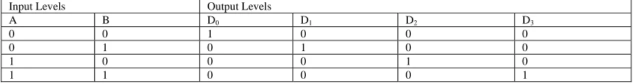
A binary code is a group of n bits that assumes upto 2n distinct combinations of one’s and zero’s, with each combination representing one element of the set that is being coded. Discrete quantities of information are represented in digital systems by binary codes. A minterm generator is a combinational circuit that converts binary information from n input lines to a maximum of 2n output lines. Suppose the input has some unused conditions then the minterm generator consist of smaller output levels compared to 2n output levels. The two inputs are decoded into four outputs, each representing one of the minterms of the two input variables. The complementor circuit provide the complement of the two inputs, and each one of the four three input majority AND function generates one of the minterm. The function table 1 may be verifying the operation of minterm generator.
Table 1: Function table of two to four line minterm generator circuit.
Input Levels Output Levels
A B D0 D1 D2 D3
0 0 1 0 0 0
0 1 0 1 0 0
1 0 0 0 1 0
1 1 0 0 0 1
circuit that computes the reverse operation of decoder circuits. A digital encoder circuit consists of 2n number of input lines and produce n number of output lines. The generated output lines represent binary code corresponding to the input lines. The Karnaugh map is providing a simple procedure for simplifying the given Boolean function. This method provides a pictorial form of a function table. A Karnaugh map is a diagram and it is made up of squares with each square represent a min term of the function that is to be simplified. Consider a new procedure for understanding and reduce the logical operations in the form of Majority of majority functions. In each square that has a Boolean one value we represent that was11-, and the square with Boolean 0 will be represent the value 00- to produce a new map method that will be pointed to as J-map denoting majority function.
QCA Implementation:
QCA computation proceeds by orientation of cells based on polarization of neighboring cells. The QCA inverter is built by neighboring QCA cells on the diagonal, which causes Coulomb forces to place the two electrons in opposing wells of the cell compared to the source. The combinational minterm generator circuit is designed with four majority gates and one inverters. The corresponding QCA implementation of combinational minterm generator circuit is shown in Figure 6. In our implementation, the total number of cells required is 167cells, with an area 462.06nmx418.00 nm.
Fig. 6: QCA implementation of Minterm generator circuit.
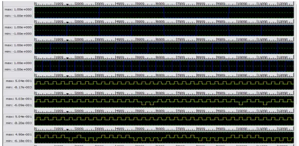
Simulation Results:
The combinational minterm generator circuit functionality is verified using QCA Designer tool ver.2.0.3. The simulated waveforms of combinational minterm generator circuit are shown in Fig.7.
The minterm generator circuit has four clocking zones. Initially clock 0 is used to get the inputs A and B. Clock 1 is used to route inputs for majority gate logic, clock 2 is used for finding majority logic and clock 3 is used to compute output. The output is available at clock 0 again. Clock 1 to 3 considered here is a sequence of setup for hold, relax and release phase, to control the flow of information in QCA circuits. Similarly, to design minterm generator circuit also need 4 clock zones are used to produce required output.
Conclusion:
The design approach and implementation of combinational minterm generator circuit is presented in this paper. The digital AND gate and OR gate was implemented with the help of three input majority gate functions and majority gate implementation of minterm generator circuit have been designed and tested using QCA Designer software. The function of the three input majority AND and OR gate function has been verified according to the truth table. The proposed layouts of combinational minterm generator circuit are significantly smaller than the circuits using CMOS technology and it reduces the area as well as complexity required for the circuit than the previous QCA circuits. The designed QCA based combinational minterm generator circuit can be used to represent only two input levels and generate only four output levels. In future, this can be extended to represent four input levels and generate sixteen output levels.
REFERENCES
Ganesh, E.N., Lal Kishore and M.J.S. Rangachar, 2008. “Implementation of Quantum cellular automata combinational and sequential circuits using Majority logic reduction method”, International Journal of Nanotechnology and Applications, 2(1).
Heumpil Cho, Student Member and Earl E. Swartzlander, 2007. “Adder Design and Analyses for Quantum-Dot Cellular Automata”, IEEE Trans. Nano., 6(3).
Townsend, W.J. and J.A. Abraham, 2004. “Complex gate implementations for quantum dot cellular automata”, in Proc. 4th IEEE Conf. Nanotechnology, pp: 625-627.
Walus, K., G. Schulhof and G.A. Jullien, 2004. “High level exploration of quantum-dot cellular automata (QCA),” in Conf. Rec. 38th Asilomar Conf. Signals, Systems and Computers, 1: 30-33.
Walus, K., G. Schulhof, G.A. Jullien, R. Zhang and W. Wang, 2004. “Circuit design based on majority gates for applications with quantum-dot cellular automata,” in Conf. Rec. 38th Asilomar Conf. Signals, Systems and Computers, 2: 1354-1357.
Walus, K., G.A. Jullien and V. Dimitrov, 2003. Computer arithmetic structures for quantum cellular automata. Asilomar Conference on Signals, Systems, and Computers.
Walus, K., G.A. Jullien, V.S. Dimitrov, 2003. “Computer Arithmetic Structures for Quantum Cellular Automata”, Asilomar Conference on Signals, Systems, and Computers, Pacific Grove, CA.
Walus, K., T. Dysart, G. Jullien and R. Budiman, 2004. “QCADesigner: A rapid design and simulation tool for quantum-dot cellular automata”, IEEE Trans. Nanotechnology, 3(1): 26-29.
Wang, W., K. Walus and G.A. Jullien, 2003. Quantum-dot cellular automata adders. IEEE Nano Conference, August 2003.
Wang, W., K. Walus, G.A. Jullien, 2003. "Quantum-Dot Cellular Automata Adders" Copyright IEEE Nano 2003 Conference, August 12-14, San Francisco, CA.